11-flues and chimneys
DESCRIPTION
Flue and chimneyTRANSCRIPT

1
Flues and Chimneys
朱信Hsin ChuProfessorDept. of Environmental EngineeringNational Cheng Kung University

2
1. Functions of the Flue System
The function of the flue in combustion equipment can be summarized quite simply: it is for the safe and effective disposal of the products of combustion.
This focuses on two considerations, namely bringing the products of combustion to the outlet of the flue at the required conditions (such as temperature and velocity), and ensuring that the location of this outlet is such that the environmental impact of the discharge is controlled.

3
There are two ways in which the dispersal of the combustion products can be effected.
If the fuel has a very low sulfur content (such as natural gas) then it is often possible to dilute the products of combustion with ambient air and to discharge the diluted mixture at a low level.
4
This may be desirable economically as it avoids the need to construct a high-level discharge, or it might be aesthetically appealing if the presence of a chimney, either outside the building or appearing at the rooftop, is thought to be undesirable.
The majority of flue systems discharge the combustion products at a high level via a flue or chimney.

5
Contemporary chimneys are generally of circular cross-section and are of metal fabrication.
An important consideration in chimney design not discussed here is the wind loads imposed on the structure, which can be carried by the fabric of the chimney itself or by external bracing such as fins or wires.

6
In addition to the steady-state loads on a chimney, vibrations can be induced by the regular shedding of vortices from the cylindrical surface (the same mechanism which causes telephone wires to hum).
The spiral “strakes” which are often attached to the upper part of a chimney are there to reduce this effect.
7
The force for moving the flue gas within the system can come from the buoyancy of the hot gas within the flue, from external fan power or from a combination of both.
In addition to maintaining the correct flow rate of gas through the flue it is essential to maintain the temperature of the gas within the flue system above the water vapor dew point, or the acid dew point if a high sulfur content fuel is being burned.
8
In terms of mechanisms, we are interested in the heat transfer and fluid flow performance of the flue, recognizing that both these considerations must be integrated in the engineering design of the flue system.

9
2. Chimney Heat Transfer
2.1 Heat Transfer Mechanism The rate of heat transfer affects the
temperatures in the system, which in turn determine the safety margin in respect of possible corrosion problems, and also the pressure difference due to buoyancy forces, known as the chimney draught.
10
The most common situation is where the temperature, composition and flow rate of the gas entering the flue are known, and the objective is to find the temperature of the gas as it is discharged from the flue.

11
The approach adopted here is to consider the flue in classical heat exchanger terms.
This approach involves two stages: evaluating an overall thermal conductance (U-value) followed by an analysis of the performance of the flue, taking into account the flows of the system fluids (flue gas and ambient air).

12
2.2 U-value of a Chimney
Consider the cross-section sketch of a chimney wall shown in Fig. 11.1 (next slide).There are three sequential stages in the steady-state heat transfer process:(1) Convective heat transfer from the hot flue
gas to the inside surface of the chimney.

14
(2) Heat transfer between the inside and outside surfaces of the chimney.If the chimney is of solid construction,
the mechanism for this will be conduction.If there is an air gap present, then a combined mode of heat transfer
(conduction/convection together with radiation) will be operating.

15
(3) Convective heat transfer from the outside surface of the chimney to the ambient air.
Under still air conditions this will be by natural convection, but in general the action of wind will induce forced
convection from the chimney.

16
These processes can be represented thus:Q = hiAi(tg-tsi)Q = hfAf(tsi-tso) (1)Q = hoAo(tso-to)
where Q is the heat flux (W)h is the heat transfer coefficient (W/m2/K)A is the area (m2)t is the temperature ( )℃
Subscripts:f: fabricg: gasi: insideo: outsides: skin

17
In equation (1) the heat transfer across the fabric has been expressed in terms of a fabric heat transfer coefficient, hf, and a cross-sectional area, Af, over which this operates.
The contributory terms to (hfAf) depend on the construction of the chimney, as will be shown later.

18
The above equations can be summarized giving:
(2)
The rate of heat transfer is conventionally represented in the form:
Q = UoAo (tg-to) (3)where Uo represents the overall heat transfer coefficient for the exchanger and Ao represents the area which is associated with it.
1 1 1g o
i i f f o o
Q t th A h A h A

19
Any of the three area Ai, Af or Ao could be used for this purpose, but here the outside surface area of the chimney (the largest of the three) has been used.
An expression for the overall U-value of the chimney is obtained by dividing equation (2) by equation (3):
(4)
1
1o o
i i f f o
o A Ah A h A h
U

20
If the chimney is of circular cross-section and does not have an appreciable taper, the areas in the above expression are given by:
where L is the length (height) of the chimney.
0 1
2
2
2 ( )
ln( / )
o o
i i
fo i
A r L
A rL
r r LA
r r

21
If the thickness of the insulation/fabric is small compared with the radius, then equation (4) simplifies to that of one-dimensional heat transfer with all the areas being equal.
The expression for the U-value is then:
(5)
where k is the thermal conductivity of the gas.
o i(r - r )1 1k
1
+i oh h
U

22
Above expression is generally sufficiently accurate for most practical purposes.
For convenience, we can replace (ro- ri) with x, the thickness of the fabric layer.

23
The thermal resistance of the fabric layer is then:
For a composite construction of n layers, the total thermal resistance is found by adding up the individual layer resistances:
2 ( / / )i
i
xK m W
k
2 ( / / )x
K m Wk

24
A common configuration for chimneys of less than 15 m height is to have an outer skin of aluminum alloy, with a low-emissivity surface, combined with a steel inner lining with an air gap of around 6 mm between the two metals.
The heat transfer across an air gap is affected by the emissivity of the surfaces and the width of the gap.

25
In general, the thermal resistance of an air gap increases with its width, but the value remains substantially constant at separations greater than 20 mm.
The following values can be taken:Low emissivity surface High emissivity
6 mm 0.18 0.120 mm+ 0.35 0.18
the units being K/m2/W.

26
To evaluate equation (5), values are needed for the inside and outside surface coefficients of heat transfer, together with the thermal resistance of the chimney fabric and a means of estimating its effective heat transfer area.

27
Inside Surface Coefficient The flow of gas in the chimney may well be driven by
buoyancy forces, but these are generated by the difference in density between the hot flue gas and the ambient air.
Under these circumstances the contribution to the buoyancy force provided by the difference in temperature between the flue gas and the inside surface of the chimney will be very small, and heat transfer from the gas to the chimney inside surface will take place by forced convection.

28
The flue gas flow regime (whether the flow is laminar, transitional or turbulent) is indicated by the value of Reynolds number:
Re = vdi/ν
where ν is the kinematic viscosity of the flue gas.

29
For a circular cross-section the characteristic dimension d is given by the diameter of the chimney.
To get some perspective on this situation we can take a range of diameters between 0.25 m and 2 m, and consider the applicable range of flue gas velocity (v) to be between 6 m/s and 20 m/s.

30
The kinematic viscosity of a gas varies with temperature, and, although values for individual gases are readily available, it is not possible to calculate accurately the viscosity of a mixture from the values and volume fractions of its constituents.
The estimated kinematic viscosity of a flue gas resulting from the combustion of a natural gas with 20% excess air is compared with the values for air in Table 11.1 (next slide).

31
Table 11.1 Kinematic viscosities for typical flue gas and air
Temperature ( )℃Kinematic viscosity (m2/s×106)
Flue gas Air
50
100
150
200
250
300
350
17
22
27
33
40
46
54
18
23
27
32
36
41
46
32
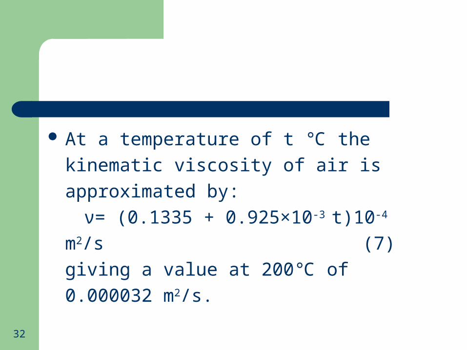
At a temperature of t the kinematic ℃viscosity of air is approximated by:
ν= (0.1335 + 0.925×10⁻³ t)10-4 m2/s
(7) giving a value at 200 of 0.000032 m℃ 2/s.
33
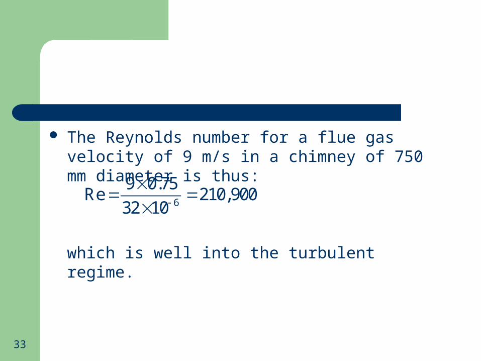
The Reynolds number for a flue gas velocity of 9 m/s in a chimney of 750 mm diameter is thus:
which is well into the turbulent regime.
6
9 0.75Re 210,900
32 10
34
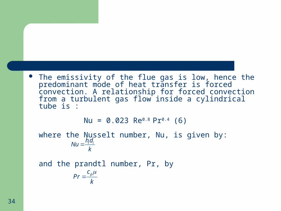
The emissivity of the flue gas is low, hence the predominant mode of heat transfer is forced convection. A relationship for forced convection from a turbulent gas flow inside a cylindrical tube is :
Nu = 0.023 Re0.8 Pr0.4 (6)
where the Nusselt number, Nu, is given by:
and the prandtl number, Pr, by
i ih dNu
k
pcPrk

35
Most gases have a value of Pr of about 0.74, and this value is substantially independent of temperature, hence equation (6) simplifies to;
Nu = 0.02 Re0.8
and the coefficient of heat transfer is obtained knowing the diameter of the tube, d, and the thermal conductivity of the gas, k.
36
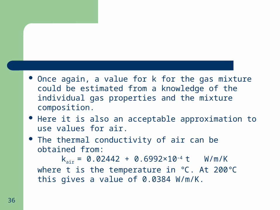
Once again, a value for k for the gas mixture could be estimated from a knowledge of the individual gas properties and the mixture composition.
Here it is also an acceptable approximation to use values for air.
The thermal conductivity of air can be obtained from:kair = 0.02442 + 0.6992×10⁻⁴ t W/m/K
where t is the temperature in . At 200 this gives a ℃ ℃value of 0.0384 W/m/K.
37
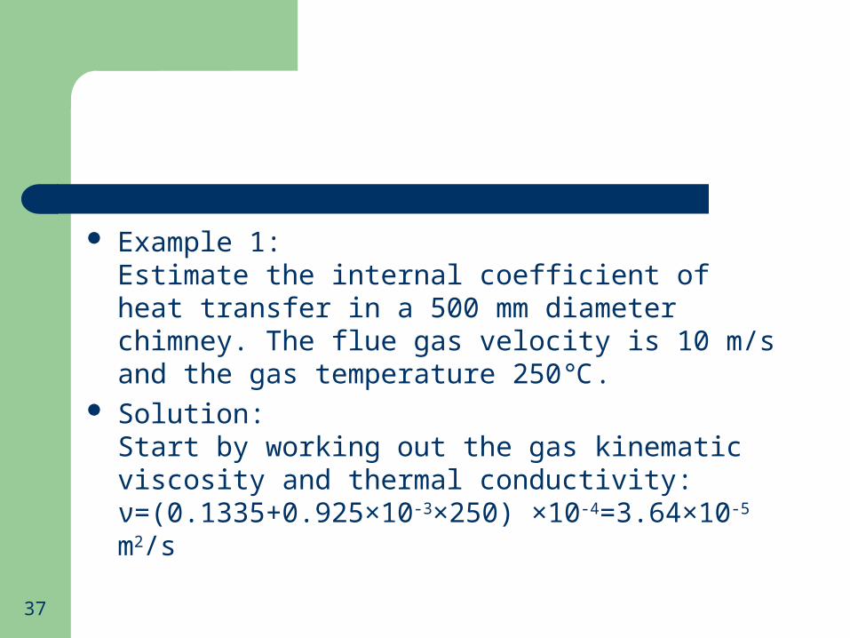
Example 1:Estimate the internal coefficient of heat transfer in a 500 mm diameter chimney. The flue gas velocity is 10 m/s and the gas temperature 250 .℃
Solution:Start by working out the gas kinematic viscosity and thermal conductivity:ν=(0.1335+0.925×10-3×250) ×10-4=3.64×10⁻⁵ m2/s
38
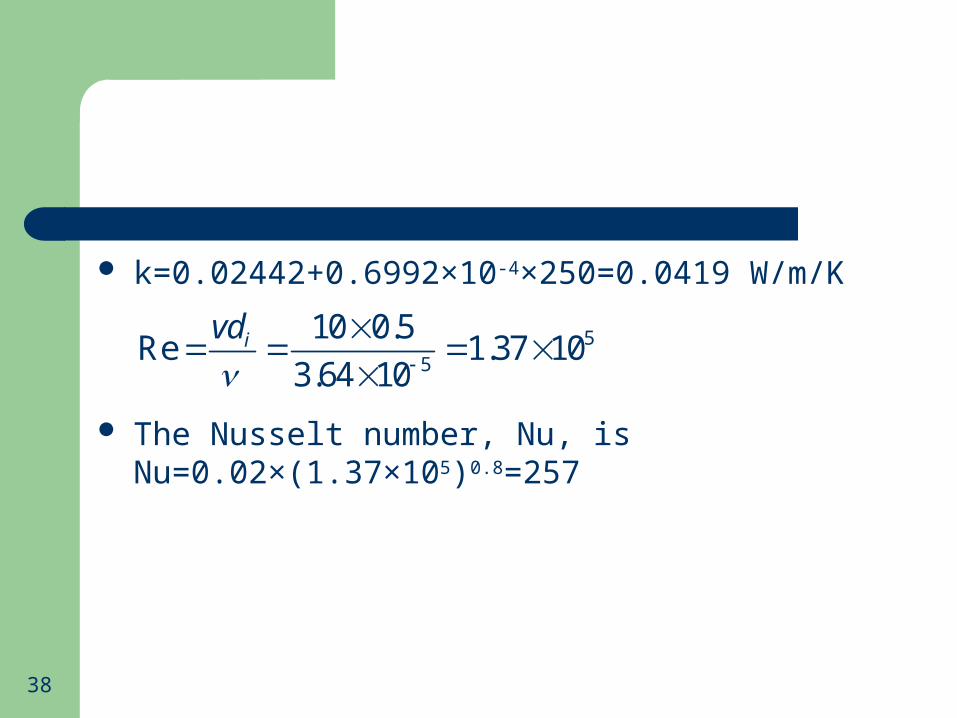
k=0.02442+0.6992×10-4×250=0.0419 W/m/K
The Nusselt number, Nu, isNu=0.02×(1.37×105)0.8=257
55
10 0.5Re 1.37 10
3.64 10ivd

39
The coefficient of heat transfer:
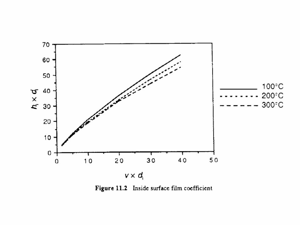
An approximate value of hi can be obtained more quickly from Fig. 11.2 (next slide), where values of hi × di (internal film coefficient × chimney diameter) are plotted as a function of v × di (flue gas velocity × chimney diameter) for flue gas temperatures ranging from 100 to 300℃.
2257 0.041921.6 / /
0.5ii
Nukh W m K
d

41
For the above example v × di=10×0.5=5 m2/s, giving a value of hi × di from the graph at 250 of 10.8 ℃W/m/K, resulting in an estimated value of:
210.8 0.5 21.6 / /ih W m K
42
Outside Surface Coefficient
The heat transfer processes taking place on the outside surface of the chimney are rather more complex than is the case for the inside surface coefficient.
Radiation heat transfer does have a part to play-the surface of the chimney will exchange heat by radiation to the surrounding environment, and the convective heat loss will be affected by the prevailing wind speed.
43
In calm conditions, the convective heat transfer from the outside surface of the chimney will be by natural convection.
As the wind velocity increases, forced convection will become the dominant mechanism.

44
A chimney exposed to the wind approximates to a cylinder with its axis at right-angles to the direction of the flow.
The relevant heat transfer relationship, valid for Reynolds numbers between 103 and 105 is:
0.6 0.30.26Re PrNu

45
Assuming a constant value for Prandtl number for air of 0.74, this expression simplifies to:
(8) In this case the Reynolds and Nusselt numbers refer
to the outside diameter, do, of the chimney.The outside convective heat transfer coefficient is then given by:
0.60.24ReNu
,c oo
Nukh
d
46
For the case of forced convection the temperature of the air has only a small effect on the value of ho, and Fig. 11.3 (next slide) shows the variation of hc,o with windspeed for a range of chimney outside diameters.


48
Example 2:Estimate the outside convective heat transfer coefficient for a 750 mm diameter chimney exposed to a wind of 10 m/s.Assume the air temperature to be 5 .℃
Solution:At 5 the kinematic viscosity of air from equation ℃(7) is:ν = (0.1335+0.925×10-3×5)10-4
= 0.0000138 m2/s

49
The Reynolds number is then:
Nu =0.024(5.43×10⁵)0.6 (from equation (8))=662.4
56
10 0.75Re 5.43 10
13.8 10

50
The thermal conductivity of air at 5 is:℃k = 0.02442+(0.6992×10-4×5)
= 0.0248 W/m/K giving an outside convective film coefficient of
,
2
662.4 0.0248
0.75
=21.9 W/m /K
c oh
51
The heat transfer from the outside surface of the chimney to the environment also contains a contribution from a radiative exchange to the surroundings.
This is not an easy mechanism to quantify accurately, as radiative heat transfer is a non-linear process with respect to temperature and is affected by the nature and configuration of the participating surfaces.

52
However, in circumstances such as these a linear approximation can be made to the radiative heat transfer component and an outside film coefficient defined in terms of the convective and radiative components thus
where εis the emissivity of the surface and hr,o is a linearized radiation surface heat transfer coefficient, which is dependent on the surface temperature of the chimney and the temperature of the surroundings.
, ,o c o r oh h h

53
For typical situations a reasonable value for hr,o is 5 W/m2/K.
The emissivity will depend on the outside finish of the chimney, and some example values are given in Table 11.2 (next slide).

54
Table 11.2 Emissivities of some surfaces
Material Emissivity
Polished aluminium
Oxidized aluminium
Polished steel
Rolled sheet steel
Galvanized Zinc
Brick
Glazed surface
Non-metallic paint
0.10
0.18
0.07
0.66
0.21
0.93
0.90
0.90
55
If we want to take into account the effects of radiation in Example 2, for the case of a dull metal finish (ε=0.2), we have:ho = 21.96 + 0.2 × 5
= 22.96 W/m2/K

56
If the chimney is insulated, the contribution of variation in ho to the overall heat transfer process is quite small, hence the approximations introduced above are justifiable.

57
Overall U-value
Bringing the inside and outside film coefficients together with the thermal resistance of the chimney fabric into the evaluation of the overall U-value of a chimney is best illustrated by a simple example.
Example 3:A flue has a height of 15 m, an external diameter of 750 mm and a construction consisting of an internal steel lining, 3 mm thick, of 50 mm mineral wool insulation (conductivity 0.04 W/m/K), and an outer skin of 1.6 mm alloy with a polished outer surface.

58
The internal and external heat transfer coefficients have been estimated as 20 and 23 W/m2/K respectively. Calculate the overall U-value.
Solution:For equation (6), neglecting the thermal resistance of the two metal layers:
2
0.051 120 0.04 23
10.746 / /oU W m K

59
The relative magnitudes of the three terms in the denominator of the above expression show that by far the most significant term in the case of an insulated flue is the thermal resistance to conduction across the insulated layer, and thus in these circumstances a high level of accuracy in the evolution of the film coefficients is unwarranted.

60
2.3 Temperature Distribution in a Chimney
In order to evaluate the overall heat transfer from the flue to the surroundings it is necessary to take into account the flow pattern of the two fluids concerned, i.e., the flue gases rising in the flue and the air flowing over the outside of the chimney.
The latter can be considered as being at a constant temperature to, hence we can construct an energy balance about a short section of the chimney:dQ = -U(t - to) dA (9)dQ = Wdt (10)

61
Where dA represents the surface area of the small section under consideration and dt is the small temperature drop of the flue gases in this section.
The term W represents the thermal capacity rate of the flue gas, and is obtained by summing the product of the mass flow rate and specific heat for each of the species present, that is:
pW = (mc ) kW/K

62
Evaluation of this expression can be a bit time-consuming.However, an approximate value of 1.476 kJ/m3/K can be assumed for the volumetric specific heat of the flue gas which, when multiplied by the volume flow rate of the gas (m3/s) gives a value for W.
The volume flow rate of flue gas can be estimated from the gas velocity and the internal cross-sectional area of the chimney.
63
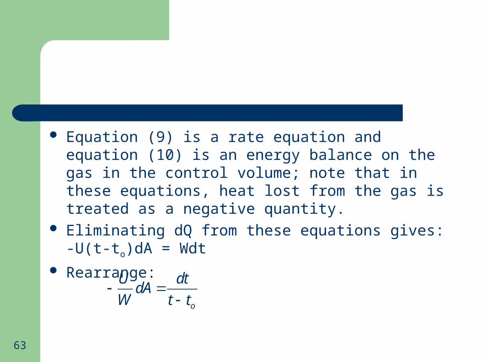
Equation (9) is a rate equation and equation (10) is an energy balance on the gas in the control volume; note that in these equations, heat lost from the gas is treated as a negative quantity.
Eliminating dQ from these equations gives:-U(t-to)dA = Wdt
Rearrange:
o
U dtdA
W t t

64
Which can be integrated:
Giving:
Hence:
(11)
2
100( )
A t
t
U dtdA
W t t
2 0
1 0
( )ln
( )
t tUA
W t t
( / )2 0 1 0( ) UA Wt t t t e
65
This expression gives the flue gas temperature t2 at the outlet of a section of the flue of area A, from a starting temperature of t1.
It is most appropriately applied to the entire flue but the expression can be solved for any number of flue section, so giving a temperature distribution along the flow path.

66
As the thermal capacity rate of the flue gas is quite high, the ratio UA/W is generally small, giving a low temperature drop in the flue gas as within the chimney.
The main function of the chimney insulation is to keep the temperature of the gas high by limiting the temperature drop between the gas and the inner lining of the chimney.

67
In the steady state, the ratio of the temperature drop across the inner boundary layer to the overall temperature difference between the gas and the outside air is equal to the ratio between the thermal resistance of the inner boundary layer to the resistance of the entire chimney wall.
68
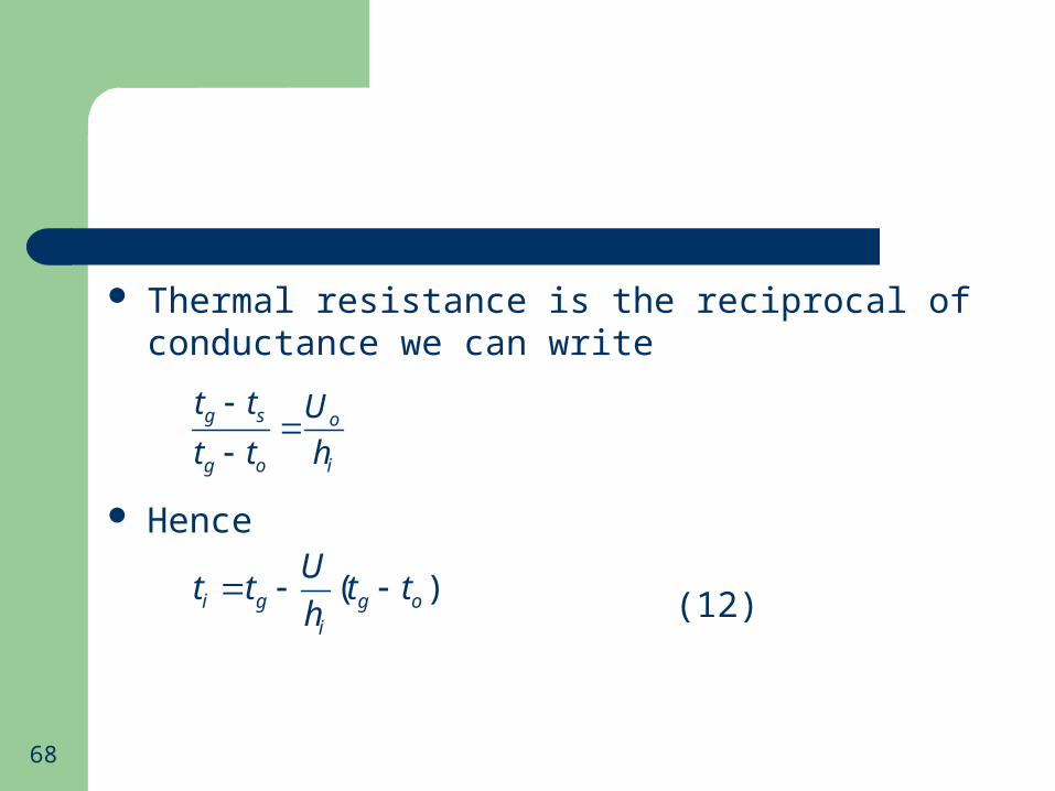
Thermal resistance is the reciprocal of conductance we can write
Hence
(12)
g s o
g o i
t t U
t t h
( )i g g oi
Ut t t t
h

69
Maintaining internal surfaces temperature well above the gas dew point is an important design consideration.
Estimation of the surface temperatures in a flue is illustrated in the following example.
Example 4:Estimate the flue gas temperature on leaving and the internal surface temperature at the flue exit for a 15 m high flue with a U-value of 3.5 W/m2/K at an outside air temperature of -3 .℃

70
The internal diameter of the flue is 1.25 m and the external diameter 1.5 m. The flue gas velocity is 4 m/s and the gas temperature on entering is 275 .℃
Solution:The first task is to find the bulk flue gas temperature at the chimney exit from equating (11).
71
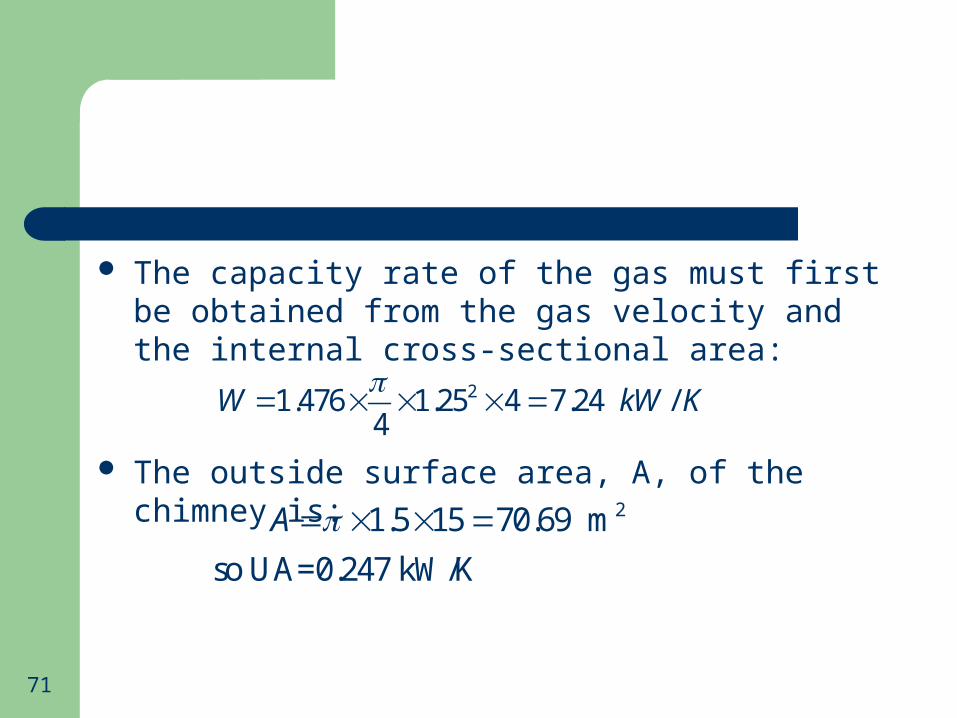
The capacity rate of the gas must first be obtained from the gas velocity and the internal cross-sectional area:
The outside surface area, A, of the chimney is:
21.476 1.25 4 7.24 /4
W kW K
2 1.5 15 70.69 m
so UA=0.247 kW/K
A
72
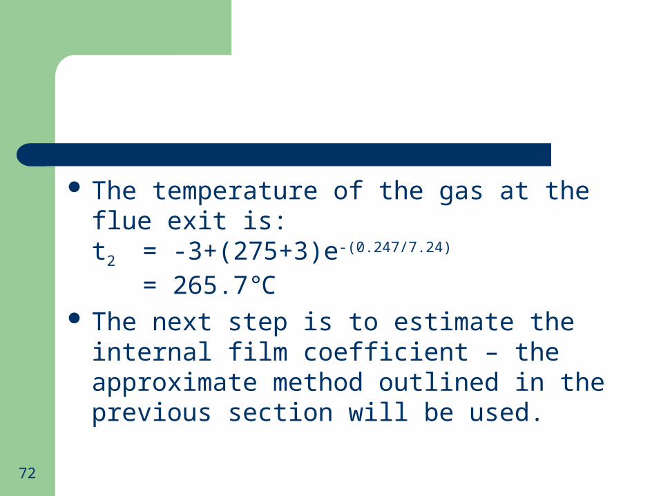
The temperature of the gas at the flue exit is:t2 = -3+(275+3)e-(0.247/7.24)
= 265.7℃ The next step is to estimate the internal film
coefficient – the approximate method outlined in the previous section will be used.

73
The value of (vdi) is 4 × 1.25 = 5, hence (hidi) will be 10.7 (from Fig. 11.2). Hence:hi = 10.7/1.25 = 8.56 W/m2/K
We can now solve equation (12) to get the internal surface temperature:
3.5265.7 265.7 3
8.56
155.8
s
o
t
C

74
A U-value of 3.5 W/m2/K is a fairly modest level of thermal insulation but would be typical of a double skin flue with a low-emissivity air gap as insulation.
The example does, however, illustrate the importance of the temperature gradient across the chimney as opposed to that along the flow path of the flue gas.

75
3. Pressure Loss
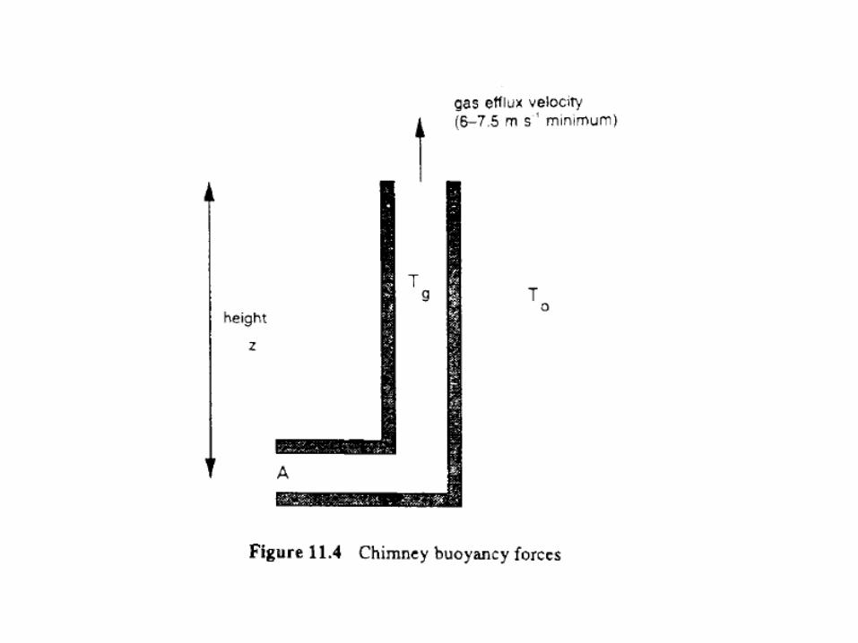
3.1 Chimney Draught The chimney contains a column of hot gas
which has a density considerably lower than that of the air surrounding it (Fig. 11.4, next slide).
This difference in density produces an apparent “suction” at the base of the flue which is known as the “chimney draught”.

77
In some instances (mainly smaller combustion equipment) this pressure difference is sufficient to overcome the resistance to flow through the boiler and the flue, and to provide the correct efflux velocity at the top of the flue.
In cases where this natural draught is insufficient, fan assistance can be employed.

78
In the majority of installations, the combustion air is supplied to the burner by an integral fan, which will have sufficient duty to propel the air through the boiler itself.
In these circumstances all the flue draught is available for providing the energy required to move the flue gas through the chimney.

79
Taking the point A in Fig. 11.4, the pressure difference due to the buoyancy of the column of hot gas in the chimney is simply equal to the relative weights of the columns of hot gas and surrounding air:Δp = zg (ρg-ρa) (13)
In this expression ρg represents the mean density of the flue gas.
80
As was shown above, the temperature drop as the gas passes through the chimney is quite small, so there would be only a small error incurred if the temperature of the gas at the flue inlet was used to evaluate the available draught.
The density of the air is primarily influenced by its temperature, but the density of the flue gas is dependent on both the temperature and composition of the gas, which will vary with different fuels and the air-to-fuel ratio.

81
The equation of state for an ideal gas:
can be written in terms of the gas density, ρ:
or
mpV RT
M
p RTM
pM
RT

82
At standard atmospheric pressure of 1.01325 bar and noting that the universal gas constant, R, is 8.314 kJ/kmol/K:
This expression can be substituted for the two density terms in equation (13), noting that the average molecular weight for air is 28.84 and incorporating g in the numerical constant:
312.1873 (kg/m ) (14)M
T
28.84118.9 (Pa/m)g
g a
M
T T
p
z

83
A further simplification can be made if we consider the molecular weight of the flue gas, Mg.
This will obviously depend on the chemical constitution of the fuel and on the air-to-fuel ratio.
Some typical values for Mg range from 27.86 (natural gas burned at 20% excess air) to 30.0 (bituminous coal burned at 20% excess air).

84
Within this range it is reasonable to take an approximate value equal to the mean molecular weight of air, i.e. 28.84, leading to the simplified expression for the chimney draught:
1 13,429 (15)g aT T
p
z

85
As an example, if the ambient temperature is -5 (268K) and the mean flue gas ℃temperature is 250 (523K), then the ℃draught, given by equation (14), is -6.24 Pa/m.
86
3.2 Flow Resistance
In a natural-draught appliance, the buoyancy force produced in the flue has to move the air through the boiler and the flue system.
Where the burner incorporates a forced air supply via a fan, it is most likely that the designer will have to ensure that an adequate pressure difference is available to overcome the resistance of the flue system itself.
87
The basis for quantifying the pressure (or energy) losses when a fluid flows through a system containing resistances due to bends, fittings and the friction of the pipe itself is:
Δp = K (v2/2g) (16)where K is the pressure loss coefficient and the bracketed term is the velocity pressure of the fluid.
88
For the case of the friction in the conduit of the chimney itself K is represented as:
K = f (L/D)where f is the friction factor which depends on both the roughness of the surface and the Reynolds number of the flow.
L: lengthD: diameter

89
For a fuller treatment of the relationships for pressure loss in pipes and ducts, the reader is referred to any standard text on fluid mechanics or the chartered Institution of Building Services Engineers, London (CIBSE) and American Society of Heating, Refrigerating and Air Conditioning Engineers (ASHRAE) handbooks.
90
If an estimate of the flue gas velocity is available, an initial estimate of the pressure loss in the flue system can be made by substituting a value for K of 5.0 in equation (16).

91
At a later stage, when the design of the flue system is more established, the pressure drop for the system can be obtained from summing up the individual contributions to the pressure loss multiplied by their respective velocity pressures:
Here K1 is the loss coefficient at the inlet to the flue duct. The second term represents the summation of all the individual losses from fittings such as bends, dampers or connectors.
1 1 2 2f Dp K K K vp K vp

92
For values of these, the reader is referred again to the handbooks; approximate example values are 0.8 for a smooth round 900 bend and 1.25 for a mitred 900 bend.
For the duct loss KD an estimate can be made from:KD = L/(30 di)

93
With regard to the exit loss K2 is equal to 1.0 and is associated with the velocity pressure in the chimney duct vp1 if the chimney discharges as a free jet into the atmosphere, but there will be an additional contributing factor (based on the velocity pressure vp2 in the smaller outlet diameter) if a tapering conical cap is used to increase the efflux velocity of the jet.
A typical value of K2 for a gradual contraction is 0.20.
94
Example 5:For the chimney described in Example 4, find the chimney draught and the pressure drop in the flue if a cap is used to accelerate the efflux velocity to 8 m/s.
Solution:In Example 4, the gas temperature on entering was 275 and the gas temperature on leaving was ℃265.7 .℃The mean temperature is thus 270.3 (543 K).℃

95
The outside air temperature is -3 (270K), hence ℃the draught, from equation (15) is:
To evaluate the pressure drop it is first necessary to estimate the density of the flue gas.This is done via equation (14):
1 1543 2703,429 Pa/m
p = -95.8 Pa
p
z
32912.1873 12.1873 0.651 /
543
Mkg m
T
96
The velocity pressure in the flue duct is then:
Assuming a friction factor of 0.033, the pressure loss coefficient for the duct, KD, is;
2
1
40.651 5.2 Pa
2vp
150.033 0.396 0.4
1.25DK

97
If the flow is accelerated to 8 m/s at the outlet, the velocity pressure is:vp2 = 5.2 × 82/42 = 20.8 Pa
Assuming a K-factor of 0.2 for the reducer, and 1.0 for the discharge of the free jet, the total pressure drop is given by:Δp = (0.4×5.2)+(1.2×20.8)=27 Pa #