11 components of optical instruments lecture 5. 22 spectroscopic methods are based on either: 1....
TRANSCRIPT

11
Components of Optical Instruments
Lecture 5

22
Spectroscopic methods are based on either:
1. Absorption
2. Emission
3. Scattering

33
Source SampleCell
DetectorWavelength Selector
Detector
Source
An Absorption Instrumental Setup
An Emission or Scattering Instrumental Setup
SampleCell
Wavelength Selector
Processor
Processor

44

5
Spectroscopic instruments dependent on any of the above mechanisms encompass common components which can be listed as:
1. A stable source of radiation2. A wavelength selector to choose a single
wavelength necessary for a certain absorption, emission or scattering process.
3. A radiation detector (transducer) that can measure absorbed, emitted or scattered radiation.
4. A signal processor that can change the electrical signal (current, voltage, or resistance) to a suitable form like absorbance, fluorescence, etc.
66
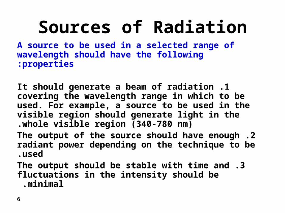
Sources of RadiationA source to be used in a selected range of wavelength should have the following properties:
1 .It should generate a beam of radiation covering the wavelength range in which to be used. For example, a source to be used in the visible region should generate light in the whole visible region (340-780 nm).
2 .The output of the source should have enough radiant power depending on the technique to be used.
3 .The output should be stable with time and fluctuations in the intensity should be minimal.

77
This necessitates the use of good regulated power supply. Sometimes, a double beam instrument is used to overcome fluctuations in the intensity of the beam with time. In such instruments, the beam from the source is split into two halves one goes to the sample while the other travels through a reference. Any fluctuations in the intensity of the beam traversing the sample will be the same as that traversing the reference at that moment. Subtraction of the reference beam from that of the sample results in excellent correction for fluctuations in the intensity of the beam.

88
Classifications of Sources
There can be several classifications of sources. One classification can be based on where their output is in the electromagnetic spectrum. A second classification can be based on whether the source is a thermal or gas filled lamps, etc. A third method of classification can be based on whether the source is a continuous or a line source. Other classifications do exist but the one which is easier to use is the method which divide sources into either continuous or line sources

99
Continuous Sources
A continuous source is a source, which has an output in a continuum of wavelengths range. An example is deuterium source in the ultraviolet (UV), which has an output in the range from 180-350 nm. Another example is the familiar tungsten lamp covering the range from 340-2500 nm, thus its output extends through the whole visible and near infrared (IR) regions.
1010
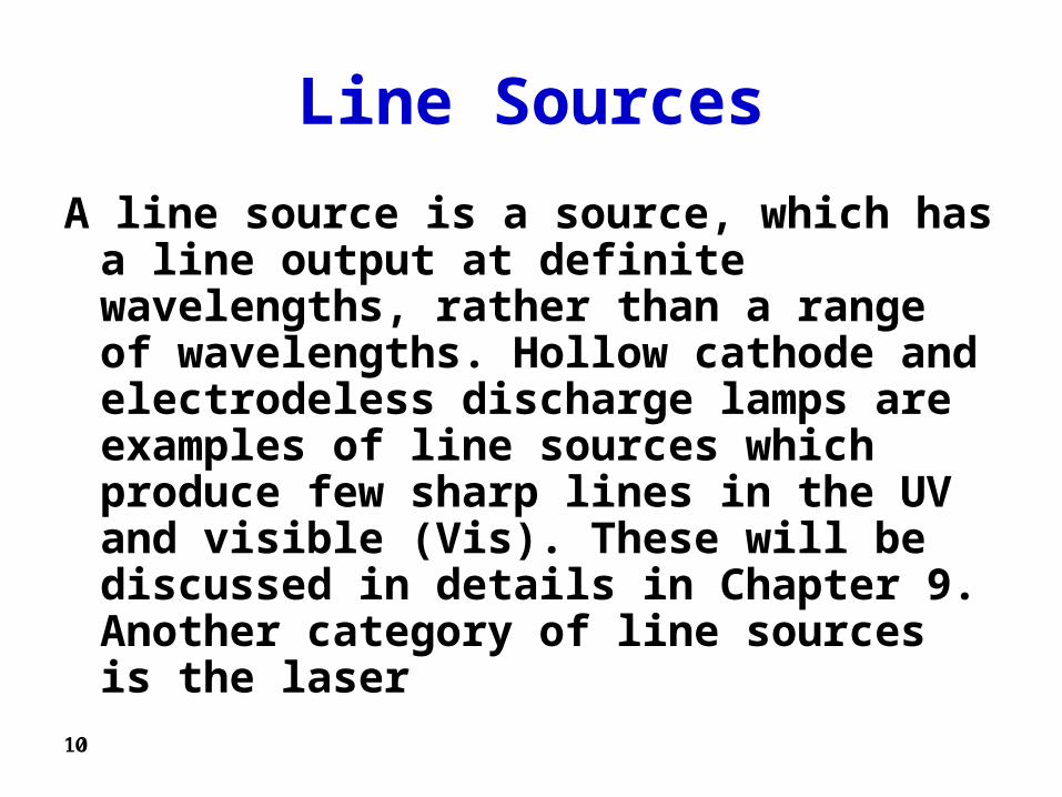
Line Sources
A line source is a source, which has a line output at definite wavelengths, rather than a range of wavelengths. Hollow cathode and electrodeless discharge lamps are examples of line sources which produce few sharp lines in the UV and visible (Vis). These will be discussed in details in Chapter 9. Another category of line sources is the laser

1111
Lasers
The term LASER is an acronym for Light Amplification by Stimulated Emission of Radiation. The first laser was introduced in 1960 and since then too many, highly important applications of lasers in chemistry were described.

1212

1313
Wavelength SelectorsWavelength Selectors
• FiltersFilters
• PrismsPrisms
• GratingsGratings
• Michelson InterferometerMichelson Interferometer

1414
Wavelength Selectors
Wavelength selectors are important instrumental components that are used to obtain a certain wavelength or a narrow band of wavelengths. Three types of wavelength selectors can be described:
I. Filters Filters are wavelength selectors that usually allow
the passage of a band of wavelengths and can be divided into three main categories:
1515
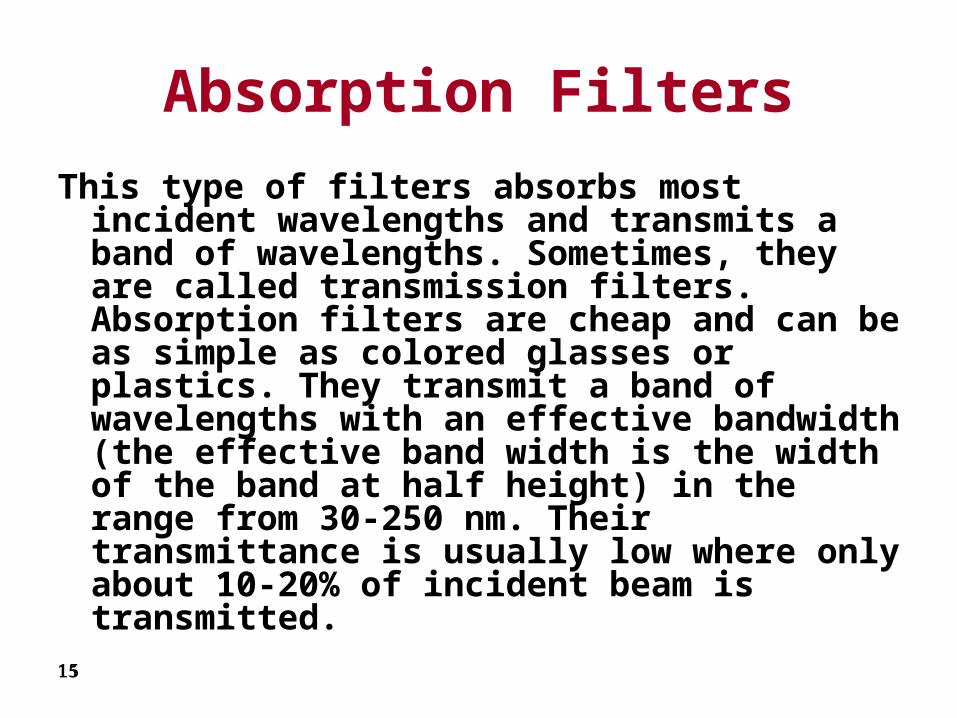
Absorption Filters
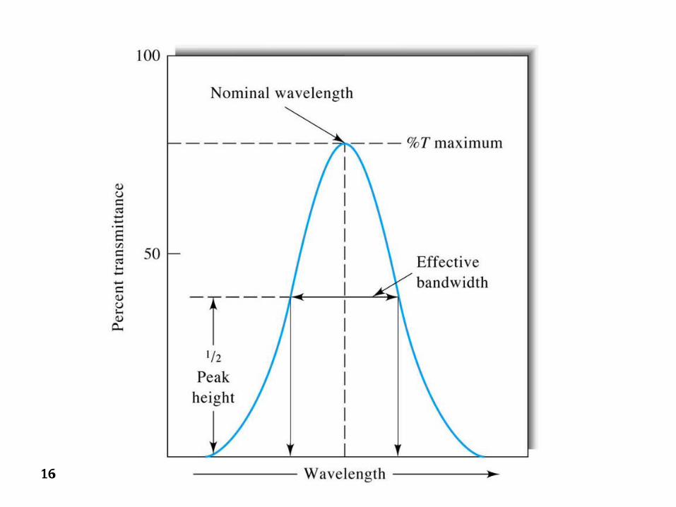
This type of filters absorbs most incident wavelengths and transmits a band of wavelengths. Sometimes, they are called transmission filters. Absorption filters are cheap and can be as simple as colored glasses or plastics. They transmit a band of wavelengths with an effective bandwidth (the effective band width is the width of the band at half height) in the range from 30-250 nm. Their transmittance is usually low where only about 10-20% of incident beam is transmitted.
1616

1717
Cut-off Filters
In this type of filters, transmittance of about 100% is observed for a portion of the visible spectrum, which rapidly decreases to zero over the remainder of the spectrum.

1818

1919
Usually, cut-off filters are not used as wavelength selectors but rather in combination of absorption filters to decrease the bandwidth of the absorption filter or to overcome problems of orders, to be discussed later. Only the combination of the two filters (common area) will be transmitted which has much narrower effective bandwidth than absorption filters alone.

2020
Filters
1. Simple, rugged (no moving parts in general)
2. Relatively inexpensive
3. Can select some broad range of wavelengths
Most often used in
1. field instruments
2. simpler instruments
3. instruments dedicated to monitoring a single wavelength range.

2121
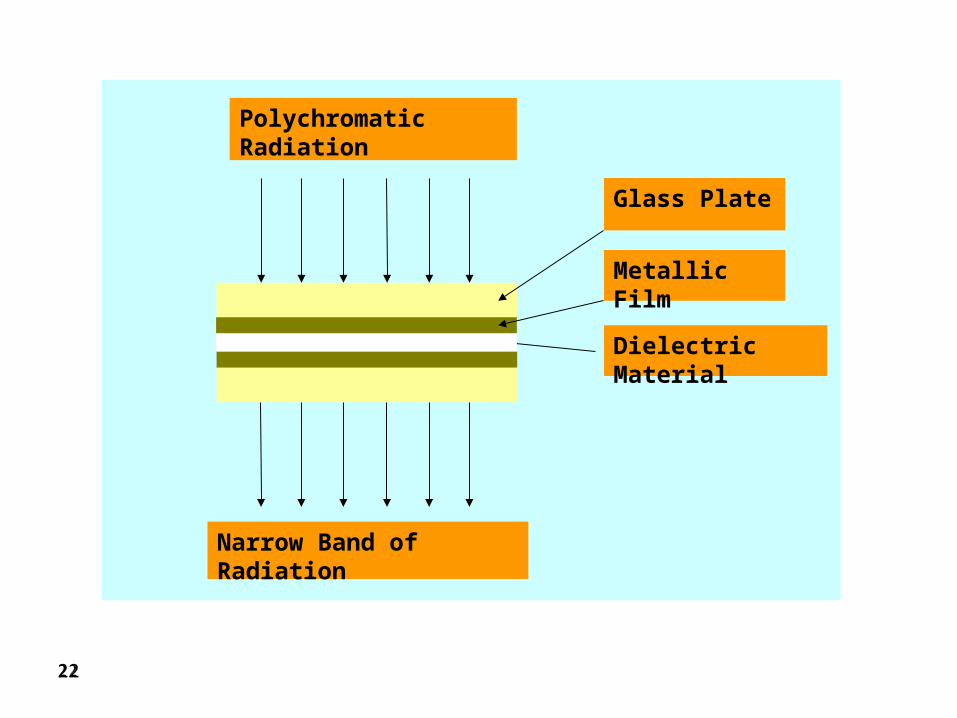
Interference Filters
These filters are sometimes called Fabry-Perot filters and are dependent on the concept of light interference. An interference filter is composed of a transparent dielectric, like calcium fluoride, sandwiched between two semitransparent metallic films. The array is further sandwiched between two glass plates to protect the filter. The thickness of the dielectric is carefully controlled, as it is this factor, which defines the resulting wavelength. Incident polychromatic radiation hits the filter at right angles and the transmitted beam will have a very narrow bandwidth. The structure of the interference filter can be depicted as in the figure below:
2222
Polychromatic Radiation
Narrow Band of Radiation
Glass Plate
Metallic Film
Dielectric Material