10260 series actuators installation, operation and ... manual.pdf · 10260 series actuators...
TRANSCRIPT

10260 Series ActuatorsInstallation, Operation and Maintenance
Manual
70-82-25-24
Rev. 21/98

10260 Series Actuators Installation, Operation and Maintenance Manual
II 10260 Series Actuator – Installation, Operation and Maintenance Manual 1/98
Copyright, Notices, and Trademarks
Printed in U.S.A. – © Copyright 1997, 1998 by Honeywell Inc.
Revision 2.0 – 1/98
While this information is presented in good faith and believed to be accurate, Honeywelldisclaims the implied warranties of merchantability and fitness for a particular purpose andmakes no express warranties except as may be stated in its written agreement with and forits customer.
In no event is Honeywell liable to anyone for any indirect, special or consequential damages.The information and specifications in this document are subject to change without notice.
CE conformity: This product is in conformance with the protection requirements of the following EuropeanCouncil Directive: 89/336/EEC, the EMC directive and 73/23/EEC, the Low Voltage Directive.Conformance of this product with any other “CE Mark” Directive(s) shall not be assumed.
CSA conformity: When specifically identified by model number this product is in conformance with theprotection requirements of the following Canadian Standards Association - Class 4813 - 02, CSA Std. C22.2No. 24-1987, CSA Std. C22.2 No. 142 - M1987. Conformance of this product with any other “CSA”Standard(s) shall not be assumed.
Attention
The emission limits of EN 50081-2 are designed to provide reasonable protection against harmful interferencewhen this equipment is operated in an industrial environment. Operation of this equipment in a residential areamay cause harmful interference. This equipment generates, uses, and can radiate radio frequency energy andmay cause interference to radio and television reception when the equipment is used closer than 30 m to theantenna(e). In special cases, when highly susceptible apparatus is used in close proximity, the user may have toemploy additional mitigating measures to further reduce the electromagnetic emissions of this equipment
! This CAUTION symbol on the equipment refers the user to the Product Manual for additional information.This symbol appears next to required information in the manual
WARNING, risk of electric shock. This symbol warns the user of a potential shock hazard wherevoltages greater than 30 Vrms, 42,4V peak, or 60 Vdc may be accessible
Protective earth terminal. Provided for connection of the protective earth (green or green/yell) supplysystem conductor.
HoneywellIndustrial Automation and Control
Automation College2820 West Kelton Lane
Phoenix, AZ 85023
(602) 313-5669

5/01 Addendum 70-82-99-04 1 of 2
AddendumTO
10260 Series ActuatorsInstallation, Operation and Maintenance Manual
Introduction
This addendum contains changes for revision 2, dated 1/98, of the 10260 Series Actuatorsoperator manual document #70-82-25-24. Please update your manual accordingly.
Delete kits 324071, 324072, and 324170 from "Field Change Kits" on page 44, as shown below:
FIELD CHANGE KITS
Description Part No.
One extra limit switch 324071
Two extra limit switches 124954
One extra limit switch to convert from MSG TableII, option 01zz to 02xx and 16xx to 17xx
324072
One extra limit switch to convert from MSG Table II,option 02xx to 03xx and 17xx to 18xx
324028
Rotary position sensor 0 - 16 vdc 324170
Rotary position sensor 4 - 20 mA 083398
Motor position 4 - 20 mA input (120V) 083399

Sensing and ControlHoneywell11 West Spring StreetFreeport, IL 61032
70-82-99-04 0501 Printed in USA www.honeywell.com/sensing
Warranty/Remedy
Honeywell warrants goods of its manufacture as being free of defective materials and faultyworkmanship. Contact your local sales office for warranty information. If warranted goodsare returned to Honeywell during the period of coverage, Honeywell will repair or replacewithout charge those items it finds defective. The foregoing is Buyer’s sole remedy and isin lieu of all other warranties, expressed or implied, including those ofmerchantability and fitness for a particular purpose. Specifications may changewithout notice. The information we supply is believed to be accurate and reliable as of thisprinting. However, we assume no responsibility for its use.
While we provide application assistance personally, through our literature and theHoneywell web site, it is up to the customer to determine the suitability of the product inthe application.

1/98 10260 Series Actuator – Installation, Operation and Maintenance Manual III
About This Document
AbstractThis document is intended for the purpose of supporting the use of the 10260 Series Actuators, theFeedback Assembly and Motor Positioner.
Revision NotesThe following list provides notes concerning all revisions of this document.
Rev. ID Date Notes
0 9/96 This is the initial release of the Honeywell version of this document. It is amerging of the original 10260 Series Actuator manual (L&N #077652) withthe manuals for the Feedback Assembly (L&N #177415) and the MotorPositioner (L&N #277751). All pertinent information has been retained andupdated.
1 4/97 This release is being made to correct various typos and to replace the oldCatalog system with the new Honeywell MSG. The Section 9, StandardDrawings has been removed.
2 1/98 This release is being made to correct various typos, omissions and to updatethe MSG. Metric equivalents have been added where appropriate.
References
Honeywell Documents
The following list identifies all Honeywell documents that may be sources of reference for the materialdiscussed in this publication.
Document Title ID # Binder Title Binder ID #
ContactsThe following list identifies important contacts within Honeywell.
Organization Telephone Address
Honeywell technical Assistance Center
TAC
1-800-423-9883 Voice 1100 Virginia Drive
Fort Washington, PA 19034
10260 Series Actuators Installation, Operation and Maintenance Manual
IV 10260 Series Actuator – Installation, Operation and Maintenance Manual 1/98
Contents
1. INTRODUCTION......................................................................................................... 11.1 Overview............................................................................................................................................ 1
Introduction....................................................................................................................................... 1In this chapter ................................................................................................................................... 1
1.2 10260 Series Actuators...................................................................................................................... 1Description........................................................................................................................................ 1
1.3 Feedback Assembly ........................................................................................................................... 2Introduction....................................................................................................................................... 2Description........................................................................................................................................ 2
1.4 Motor Positioner................................................................................................................................ 2Introduction....................................................................................................................................... 2Description........................................................................................................................................ 2
2. SPECIFICATIONS AND MODEL SELECTION GUIDE.............................................. 52.1 Overview............................................................................................................................................ 5
Introduction....................................................................................................................................... 5In this chapter ................................................................................................................................... 5
2.2 10260 Series Actuator Specifications................................................................................................ 5Physical............................................................................................................................................. 5Torque Settings of Crank Arm Bolts ................................................................................................ 6Electrical ........................................................................................................................................... 6
2.3 Feedback Assembly Specifications ................................................................................................... 7Physical............................................................................................................................................. 7Electrical ........................................................................................................................................... 7
2.4 Motor Positioner Specifications ........................................................................................................ 8Physical............................................................................................................................................. 8Electrical ........................................................................................................................................... 8
2.5 10260 Series Actuator Model Selection Guide ............................................................................... 10
2.6 Feedback Assembly Model Selection Guide................................................................................... 17
2.7 Motor Positioner Option Model Selection Guide............................................................................ 17
3. INSTALLATION........................................................................................................ 193.1 Overview.......................................................................................................................................... 19
Introduction..................................................................................................................................... 19In this chapter ................................................................................................................................. 19
3.2 Before Starting Installation.............................................................................................................. 19Unpacking....................................................................................................................................... 19Precautions for the 10260 Series Actuators.................................................................................... 19
3.3 Mechanical Installation ................................................................................................................... 20General............................................................................................................................................ 20

1/98 10260 Series Actuator – Installation, Operation and Maintenance Manual V
Linkage General Information.......................................................................................................... 20Constant Torque Linkage ............................................................................................................... 21Variable Torque Linkage................................................................................................................ 22Turnbuckle Linkage Kits ................................................................................................................ 23Pipe Linkage Kits ........................................................................................................................... 23Old and New Actuator Crank Arms ............................................................................................... 24
3.4 Electrical (Wiring) Installation........................................................................................................ 27General Wiring Recommendations................................................................................................. 2710260 Series Wiring ....................................................................................................................... 27Feedback Assembly Wiring............................................................................................................ 28Motor Positioner Wiring................................................................................................................. 28
4. FEEDBACK ASSEMBLY CALIBRATION ................................................................ 294.1 Overview.......................................................................................................................................... 29
Introduction..................................................................................................................................... 29In this chapter ................................................................................................................................. 29
4.2 Initial Calibration for 205411 Assembly (0 - 16 VDC Output) ...................................................... 29
4.3 Initial Calibration for 205446 Assembly (4 - 20 mA Output) ......................................................... 30
4.4 Reversing Cam Program.................................................................................................................. 31
4.5 Sensor Output Characterization; Plotting and Cutting Cam Profile................................................ 31Purpose of Characterization............................................................................................................ 31Cutting a Cam ................................................................................................................................. 32
5. MOTOR POSITIONER CALIBRATION .................................................................... 335.1 Overview.......................................................................................................................................... 33
Introduction..................................................................................................................................... 33In this chapter ................................................................................................................................. 33
5.2 Available Adjustments .................................................................................................................... 33
5.3 ZERO and SPAN Adjustments........................................................................................................ 34
5.4 Fail-safe Adjustments ...................................................................................................................... 34Slidewire Failure Settings............................................................................................................... 35Input Signal Loss Settings .............................................................................................................. 35
5.5 Other Adjustments........................................................................................................................... 35Filtering........................................................................................................................................... 35Deadband ........................................................................................................................................ 35
6. STARTUP ................................................................................................................. 376.1 Overview.......................................................................................................................................... 37
Introduction..................................................................................................................................... 37In this chapter ................................................................................................................................. 37
6.2 Operations Checklist ....................................................................................................................... 37
7. MAINTENANCE........................................................................................................ 39

10260 Series Actuators Installation, Operation and Maintenance Manual
VI 10260 Series Actuator – Installation, Operation and Maintenance Manual 1/98
7.1 Overview.......................................................................................................................................... 39Introduction..................................................................................................................................... 39In this chapter ................................................................................................................................. 39
7.2 10260 Series Actuator Basic Maintenance...................................................................................... 39Slidewire ......................................................................................................................................... 39Main Gear Lubrication ................................................................................................................... 39Spur Gear Lubrication .................................................................................................................... 40
7.3 Feedback Assembly Maintenance ................................................................................................... 40Troubleshooting.............................................................................................................................. 40Test Equipment ............................................................................................................................... 40Isolation Checks.............................................................................................................................. 40Replacing Components ................................................................................................................... 41
7.4 Motor Positioner Maintenance ........................................................................................................ 42
8. REPLACEMENT/RECOMMENDED SPARE PARTS............................................... 438.1 Overview.......................................................................................................................................... 43
Introduction..................................................................................................................................... 43In this chapter ................................................................................................................................. 43
8.2 10260 Series Actuator ..................................................................................................................... 43Common Spare Parts List ............................................................................................................... 43Models 0102610, 0102620, 0102640 AND 0102660..................................................................... 44Models 0102630 and 0102650........................................................................................................ 44Models 0102670, 0102680 and 0102690........................................................................................ 44FIELD CHANGE KITS.................................................................................................................. 44
8.3 Maintenance Kits for the 10260 Series Actuators........................................................................... 45Models 0102610, 0102620, 0102640 and 0102660 Kit Part Number 083070............................... 45Models 0102630 and 0102650 Kit Part Number 083071............................................................... 45Models 0102670 Kit Part Number 083072..................................................................................... 46Models 0102680 and 0102690 Kit Part Number 083073............................................................... 46
8.4 Linkage Parts ................................................................................................................................... 47Linkage Kit Part Numbers .............................................................................................................. 47
8.5 Feedback Assembly ......................................................................................................................... 47
8.6 Motor Positioner Assembly............................................................................................................. 48
8.7 Honeywell Actuator Linkage Design Software............................................................................... 48

1/98 10260 Series Actuator – Installation, Operation and Maintenance Manual VII
Tables
Table 3-1 Recommended Minimum Wire Size____________________________________________ 27Table 5-1 Available Adjustments ______________________________________________________ 33

10260 Series Actuators Installation, Operation and Maintenance Manual
VIII 10260 Series Actuator – Installation, Operation and Maintenance Manual 1/98
Figures
Figure 1-1 Rotary Position Sensor Assembly in 10260 Series Actuators__________________________ 3Figure 1-2 Motor Positioner Printed Circuit Assembly _______________________________________ 4Figure 3-1 Constant Torque Linkage_____________________________________________________ 21Figure 3-2 Constant Torque Profile______________________________________________________ 21Figure 3-3 Variable Torque Linkage_____________________________________________________ 22Figure 3-4 Variable Torque Profile______________________________________________________ 22Figure 3-5 Turnbuckle Linkage Kit______________________________________________________ 23Figure 3-6 Pipe Linkage Kit ___________________________________________________________ 23Figure 3-7 Old and New Crank Arms____________________________________________________ 24Figure 3-8 Outline and Dimensions of 010261, -620, -640, -660, -670, -680, and -690 Actuators _____ 25Figure 3-9 Outline and dimensions of 0102630 and 0102650 Actuators _________________________ 26Figure 3-10 10260 Series Actuator, Interior View __________________________________________ 27Figure 4-1 Plot of program on cam blank for 10260 Series Actuators ___________________________ 32

Introduction
1/98 10260 Series Actuator – Installation, Operation and Maintenance Manual 1
1. Introduction
1.1 Overview
Introduction
The 10260 Series Industrial Actuators consist of a motor, a gear train and an output shaft mounted in a diecast aluminum housing. In addition, a motor positioner, switches, slidewires, or a combination of both maybe mounted inside the housing. Thus, the motor drives the gear train which in turn drives the output shaft toposition a damper, valve, or similar device while operating any internally mounted switches or slidewires.
The actuators are designed for use with Honeywell controllers or other 1-5 Volt or 4-20 mA controllers.
This chapter gives the user a high level overview of the 10260 Series Actuators, the Feedback Assemblyand Motor Positioner.
In this chapter
In this chapter the following topics are discussed.
Topic See Page
Overview 1
10260 Series Actuators 1
Feedback Assembly 2
Motor Positioner 2
1.2 10260 Series Actuators
Description
All of the actuators in this series are similar. The features that are common to all actuators are listed in thespecifications. The features of a particular actuator are designated by the catalog number and suffixes.Differences in the output torque between the 0102610, 0102620, 0102640 and 0102660 Actuators resultfrom using the same motor with different gear trains. A high torque motor is provided with the 0102670,0102680 and 0102690 Actuators. The 0102630, and 0102650 motors are longer than the others, andtogether with other differences give these actuators the highest output torque. All of the actuators areequipped with self-braking motors which contribute substantially to the excellent positioning ability of theseactuators. Optional features included with the actuator are identified by suffixes to the catalog number.
10260 Series Actuators Installation, Operation and Maintenance Manual
2 10260 Series Actuator – Installation, Operation and Maintenance Manual 1/98
1.3 Feedback Assembly
Introduction
The inclusion of the rotary position sensor assembly in the actuators is intended to replace the slidewire andwiper assembly for position feedback applications. The rotary position sensor assembly for this applicationprovides two distinct advantages over the use of the slidewire:
1. it is a contactless device which reduces maintenance, and
2. its output is characterizable, i.e., its output versus input characteristic can be changed to meet variousprocess requirements.
Description
The feedback assembly consists of a position sensor, an electronics assembly, and a cam and cam followerassembly, as shown in Figure 1-1. As the output shaft rotates, the cam also rotates. The cam followertransfers cam rotation to rotation of the position sensor.
The position sensor is a rotary variable differential transformer (RVDT) which converts the physicalangular displacement into an electrical signal. The electronic assembly translates this electrical signal into4-20 mA or 0-16 vdc which is indicative of 0 - 100% output shaft travel.
1.4 Motor Positioner
Introduction
The Honeywell Motor Positioner accepts a current input signal to control the position of an actuator. TheHoneywell Motor Positioner makes positive position control possible with current adjusting type (C.A.T.)controllers.
Description
The Motor Positioner operates raise/lower switch contacts (triacs) which control power to the reversingmotor in the actuator. The actuator’s integral slidewire provides the position feedback signal to the MotorPositioner. Feedback slidewires from 100 to 1000 ohms may be used. (A 1000 ohm slidewire is mostcommon.)
Input ranges are adjustable from 0.2 to 1 V dc, up to 1 to 5 V dc. By use of an appropriate shunt resistor,controller current outputs of 4-20 mA dc, 1-5 mA dc, 10-50 mA dc, can be accommodated.
Fail-safe features are also provided. On loss of input signal, the Motor Positioner may be preset to drive themotor upscale, downscale, to a particular position, or to stop where it is. In the event of actuator slidewirefailure (broken wiper), the Motor Positioner can be set to drive the motor fully upscale or downscale.
The Motor Positioner will also accept slidewire input. For master/follower applications, the MotorPositioner will position a “follower” actuator in accordance with a slidewire input signal from a “master”actuator. The ratio between master and follower movement is adjustable by means of a span control. A biasoffset may also be induced between master and follower by means of a zero adjustment.
For follower operations in master-follower systems, the master actuator retransmitting slidewire can rangefrom 50 to 1000 ohms.
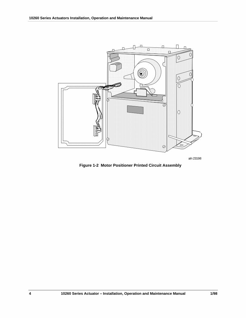
The Motor Positioner is a printed circuit board which is integrally mounted in a 10260 Series Actuatorutilizing a modified slidewire compartment cover. See Figure 1-2. The slidewire compartment cover isgasketted to provide weather resistance.

Introduction
1/98 10260 Series Actuator – Installation, Operation and Maintenance Manual 3
TOP VIEW
Cam
PlainWasher
SpringWasher
CamRetainingNut
Spring
PlateAssembly
CamFollowerAssembly
RotaryPositionSensor
ElectronicsAssembly
FRONT VIEW a/n 23197
Figure 1-1 Rotary Position Sensor Assembly in 10260 Series Actuators
10260 Series Actuators Installation, Operation and Maintenance Manual
4 10260 Series Actuator – Installation, Operation and Maintenance Manual 1/98
a/n 23198
Figure 1-2 Motor Positioner Printed Circuit Assembly

Introduction
1/98 10260 Series Actuator – Installation, Operation and Maintenance Manual 5
2. Specifications and Model Selection Guide
2.1 Overview
Introduction
This chapter provides the user with the specifications for the 10260 Series Actuators, the FeedbackAssembly and Motor Positioner.
In this chapter
In this chapter the following topics are covered.
Topic See Page
Overview 5
10260 Series Actuator Specifications 5
Feedback Assembly Specifications 7
Motor Positioner Specifications 8
10260 Series Actuator Model Selection Guide 10
Feedback Assembly Model Selection Guide 17
Motor Positioner Model Selection Guide 17
2.2 10260 Series Actuator Specifications
Physical
Dimensions:
0102630 and 0102650:
8 7/16" x 12" x12" (214 x 305 x 305 mm)
All others:
8 5/16" x 9 13/16"x 11 ¾" (211 x 249 x 298 mm)
Weight: 40 LB (18 kg) net.
44 LB (20kg) shipping
Enclosure: Aluminum alloy casting, precision machined. Finished light gray powder coat
Operating Temperature: -20 to +150°F (-30 to +650 C)
Motor: No-burnout, continuous duty, synchronous permanent magnet motor.Totally enclosed with Class H insulation. Non-coasting, stays in place onloss of power.
Output Torque: 5 to 300 lb-ft (7 to 410 NM)
10260 Series Actuators Installation, Operation and Maintenance Manual
6 10260 Series Actuator – Installation, Operation and Maintenance Manual 1/98
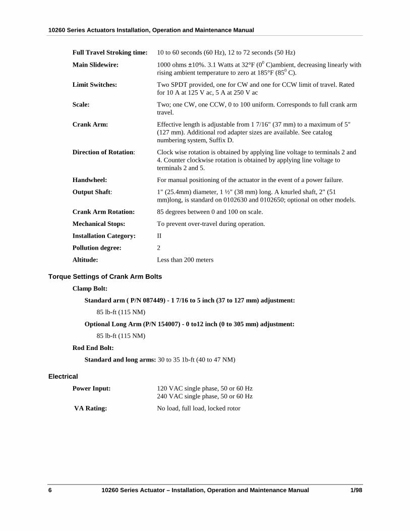
Full Travel Stroking time: 10 to 60 seconds (60 Hz), 12 to 72 seconds (50 Hz)
Main Slidewire: 1000 ohms ±10%. 3.1 Watts at 32°F (00 C)ambient, decreasing linearly withrising ambient temperature to zero at 185°F (850 C).
Limit Switches: Two SPDT provided, one for CW and one for CCW limit of travel. Ratedfor 10 A at 125 V ac, 5 A at 250 V ac
Scale: Two; one CW, one CCW, 0 to 100 uniform. Corresponds to full crank armtravel.
Crank Arm: Effective length is adjustable from 1 7/16" (37 mm) to a maximum of 5"(127 mm). Additional rod adapter sizes are available. See catalognumbering system, Suffix D.
Direction of Rotation: Clock wise rotation is obtained by applying line voltage to terminals 2 and4. Counter clockwise rotation is obtained by applying line voltage toterminals 2 and 5.
Handwheel: For manual positioning of the actuator in the event of a power failure.
Output Shaft: 1" (25.4mm) diameter, 1 ½" (38 mm) long. A knurled shaft, 2" (51mm)long, is standard on 0102630 and 0102650; optional on other models.
Crank Arm Rotation: 85 degrees between 0 and 100 on scale.
Mechanical Stops: To prevent over-travel during operation.
Installation Category: II
Pollution degree: 2
Altitude: Less than 200 meters
Torque Settings of Crank Arm Bolts
Clamp Bolt:
Standard arm ( P/N 087449) - 1 7/16 to 5 inch (37 to 127 mm) adjustment:
85 lb-ft (115 NM)
Optional Long Arm (P/N 154007) - 0 to12 inch (0 to 305 mm) adjustment:
85 lb-ft (115 NM)
Rod End Bolt:
Standard and long arms: 30 to 35 1b-ft (40 to 47 NM)
Electrical
Power Input: 120 VAC single phase, 50 or 60 Hz240 VAC single phase, 50 or 60 Hz
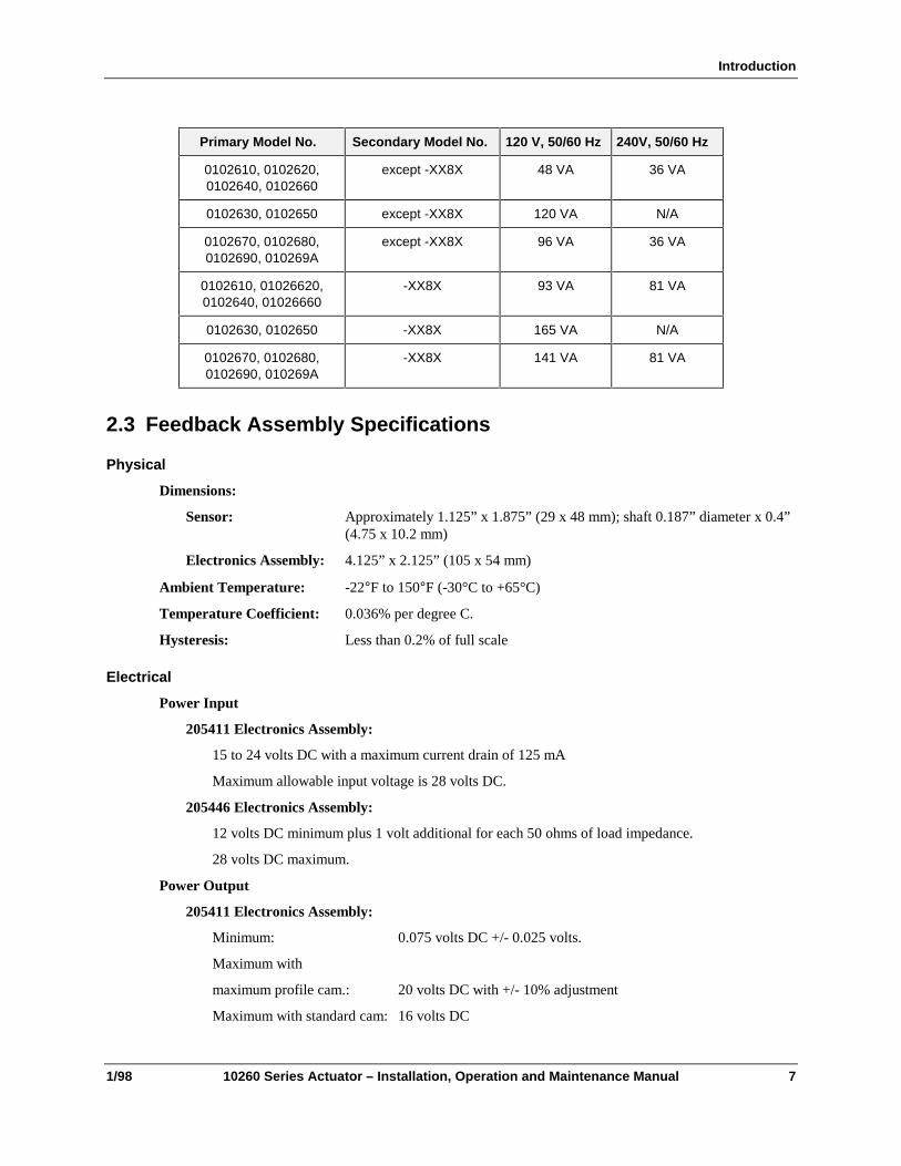
VA Rating: No load, full load, locked rotor
Introduction
1/98 10260 Series Actuator – Installation, Operation and Maintenance Manual 7
Primary Model No. Secondary Model No. 120 V, 50/60 Hz 240V, 50/60 Hz
0102610, 0102620,0102640, 0102660
except -XX8X 48 VA 36 VA
0102630, 0102650 except -XX8X 120 VA N/A
0102670, 0102680,0102690, 010269A
except -XX8X 96 VA 36 VA
0102610, 01026620,0102640, 01026660
-XX8X 93 VA 81 VA
0102630, 0102650 -XX8X 165 VA N/A
0102670, 0102680,0102690, 010269A
-XX8X 141 VA 81 VA
2.3 Feedback Assembly Specifications
Physical
Dimensions:
Sensor: Approximately 1.125” x 1.875” (29 x 48 mm); shaft 0.187” diameter x 0.4”(4.75 x 10.2 mm)
Electronics Assembly: 4.125” x 2.125” (105 x 54 mm)
Ambient Temperature: -22°F to 150°F (-30°C to +65°C)
Temperature Coefficient: 0.036% per degree C.
Hysteresis: Less than 0.2% of full scale
Electrical
Power Input
205411 Electronics Assembly:
15 to 24 volts DC with a maximum current drain of 125 mA
Maximum allowable input voltage is 28 volts DC.
205446 Electronics Assembly:
12 volts DC minimum plus 1 volt additional for each 50 ohms of load impedance.
28 volts DC maximum.
Power Output
205411 Electronics Assembly:
Minimum: 0.075 volts DC +/- 0.025 volts.
Maximum with
maximum profile cam.: 20 volts DC with +/- 10% adjustment
Maximum with standard cam: 16 volts DC

10260 Series Actuators Installation, Operation and Maintenance Manual
8 10260 Series Actuator – Installation, Operation and Maintenance Manual 1/98
205446 Electronics Assembly:
4 to 20 mA for 60° to 90° span of sensor rotation
(standard sensor cam is cut to rotate sensor 68° for 100% actuator stroke).
4 to 20 mA into 600 ohm load (load resistance dependent on power supply).
Output impedance: Equal to or less than 500 ohms
Load Requirement: 205411 - 5000 ohms
205446 - less than 600 ohms
2.4 Motor Positioner Specifications
Physical
Operating Temperature: -40°F to +150°F (-40°C to + 65°C).
Storage Temperature: -40°F to +200°F (-40°C to +93°C)
Relative Humidity: Fully operable over the range of 0-100% R.H. non-condensing.
Radio Frequency
Interference: Per SAMA PMC 33.1.
Power Supply: 120 V, 60 or 50 Hz.
For Retransmitter Slidewire: Internal 1.2 V dc.
Power requirements: 45 VA.
Terminations: Internal terminal boards.
Electrical
Input Range: 1 to 5 V dc. Use appropriate shunt resistor for current range.
Input Resistor Part No.
4-20 mA 250 ohms ± 0.1% 070756
Input Impedance: *
Input Input Impedance
4-20 mA 250 ohms
1-5 V with fail-safe Jumper W2 10K ohms
1-5 V without fail-safe Jumper W2 10M ohms
Retransmitter Slidewire: 50 to 1000 ohms.
Feedback Slidewire: 100 to 1000 ohms.
Span: Adjustable from 0.8 to 4.0 V dc.
Zero Suppression: 100% of span.
Input Filter: Adjustable to smooth input signal.
Introduction
1/98 10260 Series Actuator – Installation, Operation and Maintenance Manual 9
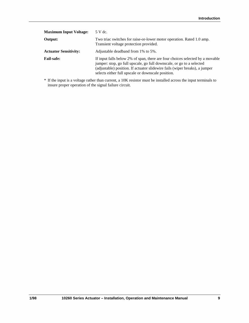
Maximum Input Voltage: 5 V dc.
Output: Two triac switches for raise-or-lower motor operation. Rated 1.0 amp.Transient voltage protection provided.
Actuator Sensitivity: Adjustable deadband from 1% to 5%.
Fail-safe: If input falls below 2% of span, there are four choices selected by a movablejumper: stop, go full upscale, go full downscale, or go to a selected(adjustable) position. If actuator slidewire fails (wiper breaks), a jumperselects either full upscale or downscale position.
* If the input is a voltage rather than current, a 10K resistor must be installed across the input terminals toinsure proper operation of the signal failure circuit.
10260 Series Actuators Installation, Operation and Maintenance Manual
10 10260 Series Actuator – Installation, Operation and Maintenance Manual 1/98
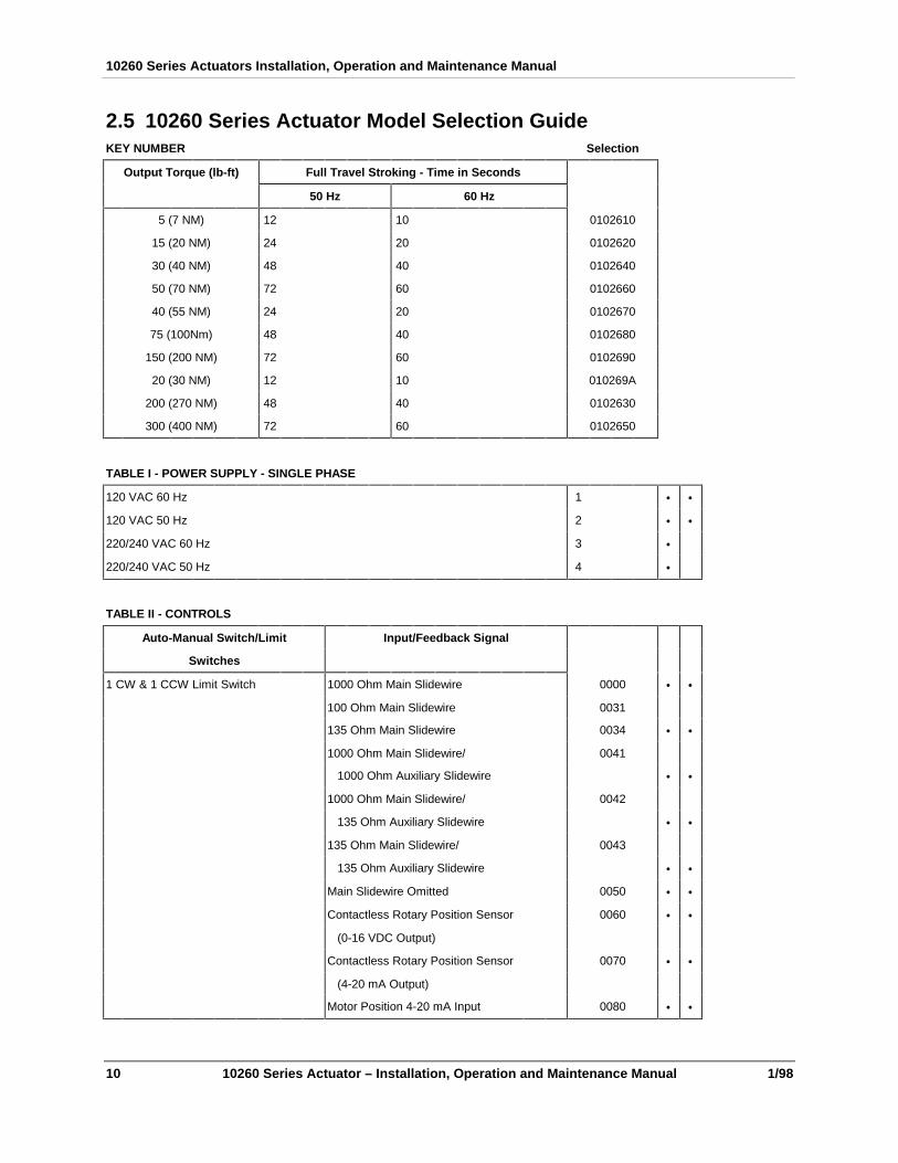
2.5 10260 Series Actuator Model Selection GuideKEY NUMBER Selection
Output Torque (lb-ft) Full Travel Stroking - Time in Seconds
50 Hz 60 Hz
5 (7 NM) 12 10 0102610
15 (20 NM) 24 20 0102620
30 (40 NM) 48 40 0102640
50 (70 NM) 72 60 0102660
40 (55 NM) 24 20 0102670
75 (100Nm) 48 40 0102680
150 (200 NM) 72 60 0102690
20 (30 NM) 12 10 010269A
200 (270 NM) 48 40 0102630
300 (400 NM) 72 60 0102650
TABLE I - POWER SUPPLY - SINGLE PHASE
120 VAC 60 Hz 1 • •
120 VAC 50 Hz 2 • •
220/240 VAC 60 Hz 3 •
220/240 VAC 50 Hz 4 •
TABLE II - CONTROLS
Auto-Manual Switch/Limit Input/Feedback Signal
Switches
1 CW & 1 CCW Limit Switch 1000 Ohm Main Slidewire 0000 • •
100 Ohm Main Slidewire 0031
135 Ohm Main Slidewire 0034 • •
1000 Ohm Main Slidewire/ 0041
1000 Ohm Auxiliary Slidewire • •
1000 Ohm Main Slidewire/ 0042
135 Ohm Auxiliary Slidewire • •
135 Ohm Main Slidewire/ 0043
135 Ohm Auxiliary Slidewire • •
Main Slidewire Omitted 0050 • •
Contactless Rotary Position Sensor 0060 • •
(0-16 VDC Output)
Contactless Rotary Position Sensor 0070 • •
(4-20 mA Output)
Motor Position 4-20 mA Input 0080 • •

Introduction
1/98 10260 Series Actuator – Installation, Operation and Maintenance Manual 11
01026_ _
10
20
40
60
70
80
90
9A 30
TABLE II - CONTROLS (continued) Selection 50
Auto-Manual Switch/Limit Input/Feedback Signal
Switches
1 CW & 1 CCW Limit Switch Motor Position 4-20 mA Input/ 0081 • •
(cont’d) Contactless Rotary Position Sensor
(4-20 mA Output)
Motor Position 4-20 mA Input/ 0083 • •
1000 Ohm Auxiliary Slidewire
1 CW & 1 CCW Limit Switch/ 1000 Ohm Main Slidewire 0100
1 Additional Auxiliary SPDT Switch 100 Ohm Main Slidewire/ 0133 • •
100 Ohm Auxiliary Slidewire
135 Ohm Main Slidewire 0134 • •
1000 Ohm Main Slidewire/ 0141
1000 Ohm Auxiliary Slidewire • •
1000 Ohm Main Slidewire/ 0142
135 Ohm Auxiliary Slidewire • •
135 Ohm Main Slidewire/ 0143
135 Ohm Auxiliary Slidewire • •
Contactless Rotary Position Sensor 0160 • •
(0-16 VDC Output)
Contactless Rotary Position Sensor 0170 • •
(4-20 mA Output)
Motor Position 4-20 mA Input 0180 • •
Motor Position 4-20 mA Input/ 0183 • •
1000 Ohm Auxiliary Slidewire
1 CW & 1 CCW Limit Switch/ 1000 Ohm Main Slidewire 0200 • •
2 Additional Auxiliary SPDT 135 Ohm Main Slidewire 0234 • •
Switches 1000 Ohm Main Slidewire/ 0241
1000 Ohm Auxiliary Slidewire • •
10260 Series Actuators Installation, Operation and Maintenance Manual
12 10260 Series Actuator – Installation, Operation and Maintenance Manual 1/98
01026_ _
10
20
40
60
70
80
90
9A 30
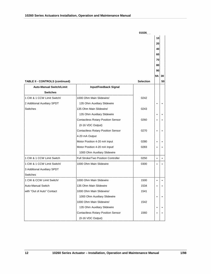
TABLE II - CONTROLS (continued) Selection 50
Auto-Manual Switch/Limit Input/Feedback Signal
Switches
1 CW & 1 CCW Limit Switch/ 1000 Ohm Main Slidewire/ 0242
2 Additional Auxiliary SPDT 135 Ohm Auxiliary Slidewire • •
Switches 135 Ohm Main Slidewire/ 0243
135 Ohm Auxiliary Slidewire • •
Contactless Rotary Position Sensor 0260 • •
(0-16 VDC Output)
Contactless Rotary Position Sensor 0270 • •
4-20 mA Output
Motor Position 4-20 mA Input 0280 • •
Motor Position 4-20 mA Input/ 0283 • •
1000 Ohm Auxiliary Slidewire
1 CW & 1 CCW Limit Switch Full Stroke/Two Position Controller 0250 • •
1 CW & 1 CCW Limit Switch/ 1000 Ohm Main Slidewire 0300 • •
3 Additional Auxiliary SPDT
Switches
1 CW & CCW Limit Switch/ 1000 Ohm Main Slidewire 1500 • •
Auto-Manual Switch 135 Ohm Main Slidewire 1534 • •
with "Out of Auto" Contact 1000 Ohm Main Slidewire/ 1541
1000 Ohm Auxiliary Slidewire • •
1000 Ohm Main Slidewire/ 1542
135 Ohm Auxiliary Slidewire • •
Contactless Rotary Position Sensor 1560 • •
(0-16 VDC Output)

Introduction
1/98 10260 Series Actuator – Installation, Operation and Maintenance Manual 13
01026_ _
10
20
40
60
70
80
90
9A 30
TABLE II - CONTROLS (continued) Selection 50
Auto-Manual Switch/Limit Input/Feedback Signal
Switches
1 CW & 1 CCW Limit Switch/ Contactless Rotary Position Sensor 1570 • •
Auto-Manual Switch (4-20 mA Output)
with "Out of Auto" Contact Motor Position 4-20 mA Input 1580 • •
Motor Position 4-20 mA Input/ 1581 • •
Contactless Rotary Position Sensor
(4-20 mA Output)
Motor Position 4-20 mA Input/ 1583 • •
1000 Ohm Auxiliary Slidewire
1 CW & 1 CCW Limit Switch/ 1000 Ohm Main Slidewire 1600 • •
1 Additional Auxiliary SPDT 135 Ohm Main Slidewire 1634 • •
Switch/Auto-Manual Switch 1000 Ohm Main Slidewire/ 1641 • •
with "Out of Auto" Contact 1000 Ohm Auxiliary Slidewire
1000 Ohm Main Slidewire/ 1642
135 Ohm Auxiliary Slidewire
135 Ohm Main Slidewire/ 1643 • •
135 Ohm Auxiliary Slidewire
Contactless Rotary Position Sensor 1660 • •
(0-16 VDC Output)
Contactless Rotary Position Sensor 1670 • •
(4-20 mA Output)
Motor Position 4-20 mA Input 1680 • •
Motor Position 4-20 mA Input/ 1683 • •
1000 Ohm Auxiliary Slidewire
1 CW & 1 CCW Limit Switch/ 1000 Ohm Main Slidewire 1700 • •
2 Additional Auxiliary SPDT 135 Ohm Main Slidewire 1734 • •
Switches/Auto-Manual Switch 1000 Ohm Main Slidewire/ 1741 • •
with "Out of Auto" Contact 1000 Ohm Auxiliary Slidewire
01026_ _
10260 Series Actuators Installation, Operation and Maintenance Manual
14 10260 Series Actuator – Installation, Operation and Maintenance Manual 1/98
10
20
40
60
70
80
90
9A 30
TABLE II - CONTROLS (continued) Selection 50
Auto-Manual Switch/Limit Input/Feedback Signal
Switches
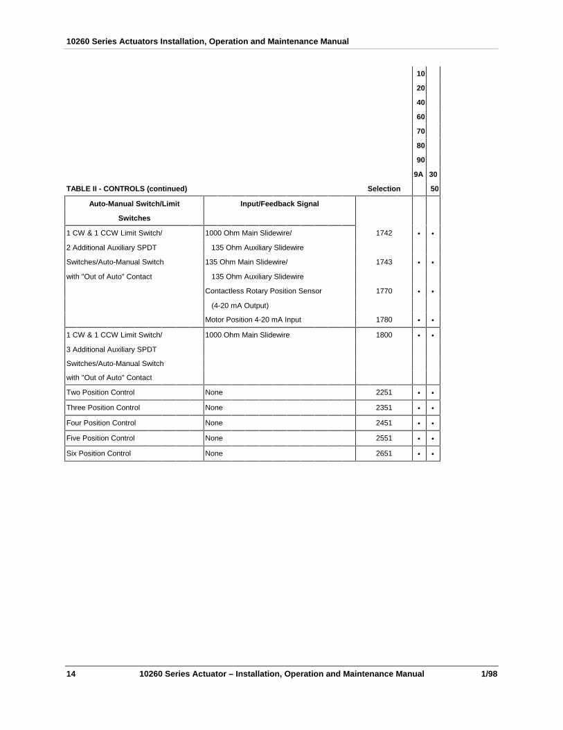
1 CW & 1 CCW Limit Switch/ 1000 Ohm Main Slidewire/ 1742 • •
2 Additional Auxiliary SPDT 135 Ohm Auxiliary Slidewire
Switches/Auto-Manual Switch 135 Ohm Main Slidewire/ 1743 • •
with "Out of Auto" Contact 135 Ohm Auxiliary Slidewire
Contactless Rotary Position Sensor 1770 • •
(4-20 mA Output)
Motor Position 4-20 mA Input 1780 • •
1 CW & 1 CCW Limit Switch/ 1000 Ohm Main Slidewire 1800 • •
3 Additional Auxiliary SPDT
Switches/Auto-Manual Switch
with "Out of Auto" Contact
Two Position Control None 2251 • •
Three Position Control None 2351 • •
Four Position Control None 2451 • •
Five Position Control None 2551 • •
Six Position Control None 2651 • •

Introduction
1/98 10260 Series Actuator – Installation, Operation and Maintenance Manual 15
01026_ _
10
20
40
60
70
80
90
TABLE III - OPTIONS 9A 30
A Shafts Standard 0XXXXXXX • •
5 Inch Extension 1XXXXXXX d •
B Weatherproof No X0XXXXXX • •
Yes NEMA 4 X1XXXXXX • •
C Projecting Scale No XX0XXXXX • •
3/4 Inch Shaft Coupling XX1XXXXX e e
3/4 Inch Shaft Coupling, Reverse Acting XX2XXXXX e e
1 Inch Shaft Coupling XX3XXXXX e e
1 Inch Shaft Coupling, Reverse Acting XX4XXXXX e e
D Crank Arm 5 Inch Standard XXX0XXXX • •
None XXX1XXXX • •
12 Inch XXX2XXXX • •
E Rod Adapter None XXXX0XXX • •
3/8 Inch XXXX1XXX • •
5/8 Inch XXXX2XXX • •
7/16 Inch XXXX3XXX • •
7/8 Inch XXXX4XXX • •
F Linkage Kits None XXXXX0XX • •
12 to 16 Inch Turnbuckle Kit XXXXX1XX • •
16 to 20 Inch Turnbuckle Kit XXXXX2XX • •
20 to 24 Inch Turnbuckle Kit XXXXX3XX • •
1 Inch Pipe Kit XXXXX4XX • •
1.5 Inch Pipe Kit XXXXX5XX • •
2 Inch Pipe Kit XXXXX6XX • •
G Approval None XXXXXX0X • •
CE-Compliant XXXXXX1X • •
CSA-Compliant XXXXXX2X f f
H Tagging None XXXXXXX0 • •
Linen (Note 2) XXXXXXX1 • •
Stainless Steel (Note 2) XXXXXXX2 • •
10260 Series Actuators Installation, Operation and Maintenance Manual
16 10260 Series Actuator – Installation, Operation and Maintenance Manual 1/98
01026_ _
10
20
40
60
70
80
90
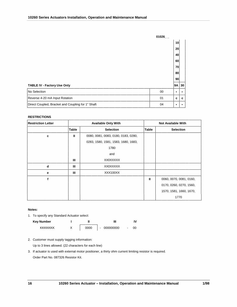
TABLE IV - Factory Use Only 9A 30
No Selection 00 • •
Reverse 4-20 mA Input Rotation 01 c c
Direct Coupled, Bracket and Coupling for 1" Shaft 04 • •
RESTRICTIONS
Restriction Letter Available Only With Not Available With
Table Selection Table Selection
c II 0080, 0081, 0083, 0180, 0183, 0280,
0283, 1580, 1581, 1583, 1680, 1683,
1780
and
III XX0XXXXX
d III XX0XXXXX
e III XXX100XX
f II 0060, 0070, 0081, 0160,
0170, 0260, 0270, 1560,
1570, 1581, 1660, 1670,
1770
Notes:
1. To specify any Standard Actuator select:
Key Number I II III IV
KKKKKKK X 0000 - 000000000 - 00
2. Customer must supply tagging information:
Up to 3 lines allowed. (22 characters for each line)
3. If actuator is used with external motor positioner, a thirty ohm current limiting resistor is required.
Order Part No. 087326 Resistor Kit.

Introduction
1/98 10260 Series Actuator – Installation, Operation and Maintenance Manual 17
2.6 Feedback Assembly Model Selection GuideThere is no separate MSG for the Feedback Assembly. It is included as part of the 10260 Series ModelSelection Guide. (Table II - options xx60, xx70 and xx81).
2.7 Motor Positioner Option Model Selection GuideThere is no separate MSG for the Motor Positioner. It is included as part of the 10260 Series ModelSelection Guide. (Table II - xx80, xx81, and xx83).

10260 Series Actuators Installation, Operation and Maintenance Manual
18 10260 Series Actuator – Installation, Operation and Maintenance Manual 1/98

Installation
1/98 10260 Series Actuator – Installation, Operation and Maintenance Manual 19
3. Installation
3.1 Overview
Introduction
This chapter provides the user with all the mechanical and electrical information required to get the 10260Series Actuator up and running in the user’s specific application. This chapter also includes the installationinstructions for the Feedback Assembly and the Motor Positioner options in the event that these optionshave been purchased by the user.
In this chapter
In this chapter the following topics are discussed.
Topic See Page
Overview 19
Before Starting Installation 19
Mechanical Installation 20
Electrical (Wiring) Installation 27
3.2 Before Starting Installation
Unpacking
Examine the shipping container carefully before opening it. If there are visible signs of damage, do not openthe container. Notify the carrier and Honeywell immediately.
If there is no visible damage, open the container and compare the contents with the packing list. Notify thecarrier and Honeywell immediately if there is equipment damage or shortage.
Please do not return goods without contacting Honeywell in advance.
Precautions for the 10260 Series Actuators
The following precautions should be taken when selecting an installation site.
• The actuator should be shielded from rain or snow unless the NEMA 4 option was selected.
• There must be sufficient space around the actuator for the removal of all covers to permit inspectionor cleaning of parts and to provide access to the handwheel.
• Auxiliary shielding should be used to protect the actuator from excessive heat or cold outside of therating of the Actuator and from corrosive elements
• Ambient temperature should not exceed 150°F (650 C).
• The minimum low temperature limit of -20°F (-300 C).

10260 Series Actuators Installation, Operation and Maintenance Manual
20 10260 Series Actuator – Installation, Operation and Maintenance Manual 1/98
3.3 Mechanical Installation
General
Install the 10260 series actuator in a convenient location in any orientation. Firmly bolt the 10260 to amounting surface that will not distort when subjected to the torque stresses generated by the actuator. Theoutput shaft of the actuator should be parallel to the output shaft of the driven device. The output shaftcrank arm is fully adjustable through 360°.
Linkage General Information
Many applications require the use of a linkage assembly and often the final control element does not have alinear torque curve. The 10260 Series Actuator linkage can be set up to achieve an optimal deliveredtorque distribution for specific applications. To assist with linkage design, Honeywell offers a linkageanalysis software package (HAL). The software can be ordered as P/N 51197910-001.
Two common linkage setups, a constant torque and a characterized torque profile, are described in thefollowing two sections.
Installation
1/98 10260 Series Actuator – Installation, Operation and Maintenance Manual 21
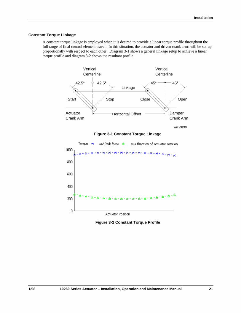
Constant Torque Linkage
A constant torque linkage is employed when it is desired to provide a linear torque profile throughout thefull range of final control element travel. In this situation, the actuator and driven crank arms will be set-upproportionally with respect to each other. Diagram 3-1 shows a general linkage setup to achieve a lineartorque profile and diagram 3-2 shows the resultant profile.
VerticalCenterline
42.5° 42.5°
VerticalCenterline
45° 45°
Start Stop Close Open
ActuatorCrank Arm
DamperCrank Arm
Linkage
Horizontal Offset
a/n 23199
Figure 3-1 Constant Torque Linkage
Figure 3-2 Constant Torque Profile

10260 Series Actuators Installation, Operation and Maintenance Manual
22 10260 Series Actuator – Installation, Operation and Maintenance Manual 1/98
Variable Torque Linkage
A variable torque linkage is employed when it is desired to provide a non-linear torque profile throughoutthe full range of final control element travel. In this general situation, the actuator and driven crank armswill be set up to provide a higher torque for seating or unseating the final control element. Diagram 3-3shows a general linkage setup to achieve a non-linear torque profile and diagram 3-4 shows the resultantprofile. Note that this linkage can be characterized in many different ways by varying start angles androtation requirements of both the Actuator Crank Arm and the Driven Arm.
VerticalCenterline
5°
VerticalCenterline
45° 45°
Close Open
ActuatorCrank Arm
DamperCrank Arm
Linkage
Horizontal Offseta/n 23200
Figure 3-3 Variable Torque Linkage
Figure 3-4 Variable Torque Profile

Installation
1/98 10260 Series Actuator – Installation, Operation and Maintenance Manual 23
Turnbuckle Linkage Kits
(See Section 8.4 for Kit numbers)
These kits are to be used where short lengths are required. These lengths range from 12 to 24 inches andrefer to the rod end center - to - center distance. All turnbuckle kits include the turnbuckle, load rod end(left-hand thread), connecting rods and locking nuts. The nut and bolt to connect the rod end to the load aresupplied by the Customer. The actuator rod end (right-hand thread), nut and bolt are supplied with theactuator. These kits can be ordered with the Actuator via section F of the Model Selection Guide orseparately as identified in section 8.4 of this manual.
Rod end, nut and bolt aresupplied with the actuator
1/2"-20 right-hand threads 0.5"-20 left-hand threads
Customer supplied nut and bolt
12 to 24 inches
a/n 23201
Figure 3-5 Turnbuckle Linkage Kit
Pipe Linkage Kits
(See Section 8.4 for Kit numbers)
These kits are used for linkage lengths from 24 to 120 inches (60 to 305 cm) . All pipe linkage kits includethe mechanical pipe couplings, load rod end (left-hand thread), connecting rods and locking nuts. TheCustomer must supply a piece of schedule 40 pipe * (both ends with right-hand NP threads) and a nut andbolt to connect the rod end to the load. The actuator rod end (right-hand thread), nut and bolt are suppliedwith the actuator. These kits can be ordered with the Actuator via section F of the Model Selection Guideor separately as identified in section 8.4 of this manual.
Rod end, nut and bolt aresupplied with the actuator
1/2"-20 right-hand threads 1/2"-20 left-hand threads
Customer supplied nut and bolt
24 to 120 inches
Customer supplied pipe*
* cut to sizewith
standard NPT both ends a/n 23202
Figure 3-6 Pipe Linkage Kit
*Pipe length = Overall linkage length minus (-) 17 inches (43 cm).
10260 Series Actuators Installation, Operation and Maintenance Manual
24 10260 Series Actuator – Installation, Operation and Maintenance Manual 1/98
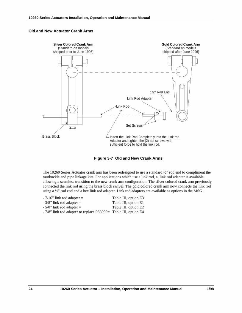
Old and New Actuator Crank Arms
Silver Colored Crank Arm(Standard on models
shipped prior to June 1996)
Gold Colored Crank Arm(Standard on models
shipped after June 1996)
1/2" Rod End
Link Rod Adapter
Link Rod
Set Screws
Brass Block Insert the Link Rod Completely into the Link rodAdapter and tighten the (2) set screws withsufficient force to hold the link rod.
Figure 3-7 Old and New Crank Arms
The 10260 Series Actuator crank arm has been redesigned to use a standard ½” rod end to compliment theturnbuckle and pipe linkage kits. For applications which use a link rod, a link rod adapter is availableallowing a seamless transition to the new crank arm configuration. The silver colored crank arm previouslyconnected the link rod using the brass block swivel. The gold colored crank arm now connects the link rodusing a ½” rod end and a hex link rod adapter. Link rod adapters are available as options in the MSG.
- 7/16” link rod adapter = Table III, option E3- 3/8” link rod adapter = Table III, option E1- 5/8” link rod adapter = Table III, option E2- 7/8” link rod adapter to replace 068099= Table III, option E4

Installation
1/98 10260 Series Actuator – Installation, Operation and Maintenance Manual 25
a/n 23204
Figure 3-8 Outline and Dimensions of 010261, -620, -640, -660, -670, -680, and -690Actuators

10260 Series Actuators Installation, Operation and Maintenance Manual
26 10260 Series Actuator – Installation, Operation and Maintenance Manual 1/98
Figure 3-9 Outline and dimensions of 0102630 and 0102650 Actuators
a/n 23205

Installation
1/98 10260 Series Actuator – Installation, Operation and Maintenance Manual 27
3.4 Electrical (Wiring) Installation
ATTENTION:
All wiring must be done by qualified technicians and must conform to national or local electrical codes.
General Wiring Recommendations
In general, stranded copper wire should be used. Unless locally applicable codes dictate otherwise, therecommended minimum wire sizes in Table 3-1 should be observed.
Table 3-1 Recommended Minimum Wire Size
Gage No. Description
14 Earth ground wire to common power supply.
18 Earth ground wire to single actuator. 120/240 V ac line leads. +24 V and common signalleads.
10260 Series Wiring
The external wiring connections should be made according to the wiring diagram furnished with the 10260series Actuator. Wiring diagrams are either in the manual supplied with the Actuator or on the inside of theterminal cover.
Figure 3-10 10260 Series Actuator, Interior View
!
!
a/n 23206

10260 Series Actuators Installation, Operation and Maintenance Manual
28 10260 Series Actuator – Installation, Operation and Maintenance Manual 1/98
Feedback Assembly Wiring
All wiring connections to the sensor assembly are made at the terminal board located in the lower section ofthe 10260 Series Actuator. Figure 3-15 is a typical wiring diagram for an actuator with feedbackelectronics. Verify wiring connections using the wiring diagram supplied with each actuator.
Motor Positioner Wiring
CAUTION
The ground terminal must be connected to a reliable earth ground for proper operation and to comply withOSHA and other safety codes.
NOTE:
As indicated, if the control signal input is to be a voltage rather than current, connect a 10 K resistor across theinput terminals.
A one-inch tapped hole exits for customer conduit connections. All wiring connections to the sensorassembly are made at the terminal board located in the lower section of the 10260 Series Actuator. Figure 3-15 is a typical wiring diagram for an actuator with feedback electronics. Verify wiring connections using thewiring diagram supplied with each actuator.
The following is the procedure for wiring the Motor Positioner to the 10260 Series Actuator.
Step Action
1 Connect the AC lines to the power terminal board.
2 Connect the hot side of the line to terminal 22 and the neutral side of the line to terminal 2.*
3 If the neutral side of the line cannot be grounded, add an isolating transformer electrically betweenthe power supply and the Motor Positioner and ground terminal 2.
*The hot line terminal number can change depending on options specified. Verify correct terminal using thewiring diagram supplied with actuator.
!
!

Feedback Assembly Calibration
3/97 10260 Series Actuators – Installation, Operation and Maintenance Manual 29
4. Feedback Assembly Calibration
4.1 Overview
Introduction
In calibrating the feedback assembly, it is necessary to determine whether the output is rotating in aclockwise or counterclockwise direction. Clockwise and counterclockwise rotation is the direction of theoutput shaft when facing the end of the shaft. Clockwise rotation moves the pointer from 100% to 0% on thescale (left hand pointer). If the particular application calls for a counterclockwise rotation (right handpointer), the cam and cam follower assembly must be changed as instructed in Section 4.4.
In this chapter
In this chapter the following topics are discussed.
Topic See Page
Overview 29
Initial Calibration for 205411 Assembly (0 - 16 VDC) 29
Initial Calibration for 205446 Assembly (4 - 20 mA) 30
Reversing Cam Program 31
Sensor Output characterization; Plotting and Cutting Cam Profile 31
4.2 Initial Calibration for 205411 Assembly (0 - 16 VDC Output)Energize the equipment by applying the d-c voltage. Then calibrate the sensor according to the followingprocedure.
Step Action
1 Rotate the actuator shaft to the minimum stroke limit (0%). Set the cam (figure 1.1) so that the camfollower is against the zero position on the cam. Tighten the cam retaining nut.
2 Connect a voltmeter (accuracy 3% or better) to pins 3 (+) or 4 (-) of the 205411 circuit card andloosen the setscrews on the cam-follower assembly.
3 Rotate the sensor’s shaft, in the direction that the follower normally moves due to cam rotation, untilthe meter indicates an increasing voltage.
4 Reverse the shaft rotation until the voltage decreases to between 0.05 and 0.1 volt d-c. Retightenthe setscrews.
5 Check the sensor-shaft adjustment by manually moving the follower off of the cam surface; theoutput should immediately begin to increase.

10260 Series Actuators Installation, Operation and Maintenance Manual
30 10260 Series Actuators – Installation, Operation and Maintenance Manual 3/97
Step Action
6 Rotate the actuator shaft to the 100% position. The cam-follower should now be resting on the 85degree mark (85 degrees is the maximum actuator stroke). On standard cams, the follower travel willhave been 100% of maximum, and the sensor shaft will have rotated 68 degrees.
7 The output voltages should be 16V. If necessary, adjust the R1 potentiometer on the 205411 circuitcard to obtain a meter reading of 16 ± 0.5V.
8 Check for 8V to 12V across test points T (+) and C (-) on the 205411 card. A low reading indicatesthe cam profile is wrong or the sensor assembly is faulty, resulting in poor operation at the ambienttemperature limits.
9 Return the actuator to the 0% position and recheck the zero position voltage as in steps 2 and 3.
4.3 Initial Calibration for 205446 Assembly (4 - 20 mA Output)Energize the equipment. Then calibrate the sensor according to the following procedure.
Step Action
1 Position actuator to the minimum stroke limit (0%).
2 Zero the cam-follower on the cam so that the cam-follower is against the zero position on the cam.Tighten the cam retaining nut.
3 Connect a high impedance digital voltmeter (DVM) between TP2 and terminal 4 (-). The voltmeterwill measure between 0.4 VDC and 2.0 VDC.
4 Rotate the Zero potentiometer R11 fully counterclockwise. Loosen the set screws on the cam-follower assembly.
5 Rotate the sensor’s shaft, in the direction that the follower normally moves due to cam rotation, untilthe meter indicates an increasing voltage.
6 Reverse the shaft rotation until the voltage is a minimum. Retighten the set screws.
7 Turn the Zero potentiometer R11 clockwise until 0.4 VDC is measured on the meter.
8 Position the actuator shaft to the maximum stroke limit (100%).
9 Adjust the Range potentiometer R10 for 2 VDC +/- .02 VDC.
10 Turn the Zero potentiometer R11 clockwise until 0.4 VDC is measured on the meter.
11 Position the actuator shaft to the maximum stroke limit (100%). The voltage should be 0.4 VDC. Ifnot, loosen the set screw and turn the sensor shaft to obtain the desired 0.4 VDC reading.
12 Tighten the set screw and repeat steps 5 through 7 until the .4 VDC +/- 0.1 VDC and 2 VDC +/- 0.02VDC indications correspond to their respective limits.

Feedback Assembly Calibration
3/97 10260 Series Actuators – Installation, Operation and Maintenance Manual 31
4.4 Reversing Cam ProgramIf the cam program requires a 0% to 100% output instead of the conventional 100 to 0% output forclockwise rotation of the output shaft, proceed as follows:
Step Action
1 Remove the cam from the shaft by removing the cam retaining nut and washers as indicated inFigure 1-1.
2 Unhook the cam follower spring from the screw in the upper stud mounting. Then loosen thesetscrews in the cam follower assembly and remove this assembly.
3 Reverse the positions of the spring and cam roller on the follower assembly. This entails removingthe spring and roller. Unscrew the roller retaining screw and replace the roller in the hole where thespring was hooked. Then hook the spring in the hole where the roller was located.
4 Remove the screw in the upper stud to which the other end of the spring was hooked and replace itin the lower stud. Tighten it securely.
5 Replace the cam follower assembly on the sensor shaft. Hook the free end of the spring on thescrew in the lower stud.
6 Replace the cam on the shaft, in reverse position from that of step 1 above before removal.
7 Calibrate the sensor assembly as outlined in Section 4.2 or 4.3, except that instead of setting thecam in the 0 -degree position, set it at the position corresponding to 100% output.
8 Figure 4-1 shows the assembly for clockwise rotation. To change from counterclockwise rotation toclockwise rotation, ensure that the final assembly is as shown in Figure 4-1.
4.5 Sensor Output Characterization; Plotting and Cutting Cam Profile
Purpose of Characterization
The purpose of characterization is to provide a linear and proportional relationship between the feedbacksignal to the controller and the process effect caused by the corresponding actuator motion. Control signal,actuator travel, and valve angle opening, may all be directly proportional to each other on a straight linebasis. However, the medium affected by the valve or final control element, i.e., flow, may not be.
For example, full output (100% flow) occurs at a 60-degree opening, 20% output at a 30-degree opening,and so on. Under the conditions outlined above, this is then a plot indicative of the feedback signal versusprocess effect characteristic.
If, due to interconnecting linkages, the actuator travel and valve angle opening are not directly proportional,then this non-linearity would need to be plotted. From this curve and the plot of the example describedabove, a relationship of actuator travel versus output (flow) could be obtained to define the feedback signalversus process effect characteristic.
The idea now is to design a cam to match these characteristics. Starting with the VALVE OPENING, 10,20, 30, 40, etc., proceed upward until these lines intersect the curve; then read off the correspondingPERCENT OF MAXIMUM FLOW. Transfer these values to graph. This is the plot of the program forwhich the cam must be cut. The procedure for cutting a cam is discussed in the section, Cutting a Cam.
If the characteristics of the final control device (valve in this case) cannot be obtained directly from a graphsupplied with that device, then a curve must be plotted by the user to determine the non-linearity. Forexample, if flow cannot be measured directly for corresponding valve openings, the effect of the flow on the

10260 Series Actuators Installation, Operation and Maintenance Manual
32 10260 Series Actuators – Installation, Operation and Maintenance Manual 3/97
process can be measured instead. As stated above, control signal, actuator travel, and valve angle opening,were all assumed to be proportional to teach other on a straight line basis. Thus, by setting the valve atvarious openings and observing the corresponding change of the measuring instrument from a desiredcontrol point, a plot of the non-linearity can be obtained. Note that the process must be allowed to “soakout” after each change in valve setting. Otherwise, results will be erroneous.
Another typical application in which characterization is useful is in those requiring “overrun”, i.e., goingpast the point of zero change in feedback to provide spring take-up or tight shutoff.
Cutting a Cam
The method of cutting a program is essentially the same for either cam. In planning a profile, the point toremember is that the plot is made of angular rotation in percent of maximum angular rotation versuspercent of maximum output voltage. For example, suppose a cam is desired with the characteristicsdescribed in the section, Purpose of Characterization.
Proceed as follows:
Step Action
1 Starting with the zero degree line on the cam, mark the percent of angular range (which correspondsto the angular rotation in degrees, i.e., 8.5, 17, 23.5, or 12, 24, 36, etc.) versus percent of outputvoltage for each major division.
2 With these points as centers, scribe 3/16” diameter circles or drill 3/16” diameter holes as indicatedin Figure 4-1.
3 Draw a smooth tangent to these 3/16” circles or holes at the points nearest the center of the cam.
4 Cut away all material outside this outline. Remove all burrs and smooth the periphery of the cam.
Figure 4-1 Plot of program on cam blank for 10260 Series Actuators
a/n 23215

Motor Positioner Calibration
3/97 10260 Series Actuators – Installation, Operation and Maintenance Manual 33
5. Motor Positioner Calibration
5.1 Overview
Introduction
If the Motor Positioner option has been purchased by the user, it’s calibration is considered as a part of the10260 Series Actuator preliminary adjustment sequence. Once all adjustments have been made, the MotorPositioner will be fully operational.
In this chapter
In this chapter the following topics are discussed.
Topic See Page
Overview 33
Available Adjustments 33
Zero and Span Adjustments 34
Fail-safe Adjustments 34
Other Adjustments 35
5.2 Available AdjustmentsOperating adjustments are located on the printed circuit board accessed by removing casting which coversslidewire/switch compartment. Altogether, there are two jumpers and five potentiometers with the followingdesignations and functions:
Table 5-1 Available Adjustments
Adjustment Marking Function
Jumper W1 Selects fail-safe actuator position if actuator slidewire wiperbreaks. Selects full up or full down. Remove W1 to disable fail-safe feature.
Jumper W2 Selects fail-safe actuator position if input signal is lost. Selectsstop, or a particular position determined by R14. Remove W2 todisable fail-safe feature.
Potentiometer Filter, R1 Input signal filter adjustment.
Potentiometer Span, R7 Input signal span adjustment.
Potentiometer Zero, R11 Input signal zero adjustment.
10260 Series Actuators Installation, Operation and Maintenance Manual
34 10260 Series Actuators – Installation, Operation and Maintenance Manual 3/97
Adjustment Marking Function
Potentiometer Failsafe Set, R14 Adjusts fail-safe position of actuator on loss of input signal.Must be enabled by W2.
Potentiometer D.U.SENS., R19 Adjusts actuator motor deadband from 1% to 5%.
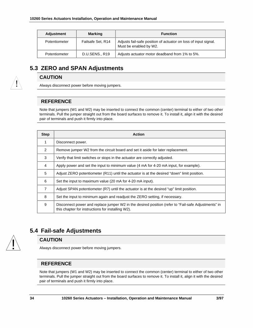
5.3 ZERO and SPAN Adjustments
CAUTION
Always disconnect power before moving jumpers.
REFERENCE
Note that jumpers (W1 and W2) may be inserted to connect the common (center) terminal to either of two otherterminals. Pull the jumper straight out from the board surfaces to remove it. To install it, align it with the desiredpair of terminals and push it firmly into place.
Step Action
1 Disconnect power.
2 Remove jumper W2 from the circuit board and set it aside for later replacement.
3 Verify that limit switches or stops in the actuator are correctly adjusted.
4 Apply power and set the input to minimum value (4 mA for 4-20 mA input, for example).
5 Adjust ZERO potentiometer (R11) until the actuator is at the desired “down” limit position.
6 Set the input to maximum value (20 mA for 4-20 mA input).
7 Adjust SPAN potentiometer (R7) until the actuator is at the desired “up” limit position.
8 Set the input to minimum again and readjust the ZERO setting, if necessary.
9 Disconnect power and replace jumper W2 in the desired position (refer to “Fail-safe Adjustments” inthis chapter for instructions for installing W2).
5.4 Fail-safe Adjustments
CAUTION
Always disconnect power before moving jumpers.
REFERENCE
Note that jumpers (W1 and W2) may be inserted to connect the common (center) terminal to either of two otherterminals. Pull the jumper straight out from the board surfaces to remove it. To install it, align it with the desiredpair of terminals and push it firmly into place.
!
!

Motor Positioner Calibration
3/97 10260 Series Actuators – Installation, Operation and Maintenance Manual 35
Slidewire Failure Settings
Select the fail-safe setting for the unlikely event of a actuator slidewire failure, which would cause loss ofposition feedback signal (broken slidewire wiper). There are two fail-safe choices: actuator to lower limit oractuator to upper limit. To disable this fail-safe feature, remove W1.
1. To cause the actuator to travel to its upper limit if there is a slidewire failure, place jumper W1 so thatit connects the center and “UP” terminals.
2. To cause the actuator to travel to its lower limit, place W1 so that it connects the center and the“DOWN” terminals.
Input Signal Loss Settings
Select the fail-safe setting for the event of a loss of input signal (signal from the controller to the MotorPositioner). There are two fail-safe choices, selectable by jumper W2: stop the actuator immediately, orbring the actuator to a stop at some particular position.
1. To cause the actuator to stop immediately if input signal is lost, install W2 so that it connects the centerand “STOP” terminals.
2. To cause the actuator to move to a particular position if input signal is lost, place W2 so that it connectsthe center and “SET POS,” terminals. Then select the particular positioner that you want, as follows(you may select fully up, fully down, or any point in between).
3. With the W2 jumper installed in “SET POS” position, apply power and interrupt the input signal. Theactuator will move to some random position and stop.
4. Adjust FAILSAFE SET potentiometer (R14) until the actuator is positioned at the desired fail-safepoint.
To disable this fail-safe feature, remove W2.
5.5 Other Adjustments
Filtering
If the input signal to the Motor Positioner contains transients or spurious signals, hunting or chattering ofthe actuator may occur. Use the FILTER potentiometer (R1) to smooth the input signal. Turn R1 clockwiseto increase filtering.
Deadband
It is sometimes desirable to introduce some amount of “deadband” between the Motor Positioner and theactuator. (Within this “deadband” zone, the actuator can be moved manually for some distance back andforth without causing a correcting signal from the Motor Positioner.)
The adjustment for “deadband” or “Actuator Sensitivity” is potentiometer R19, labeled “D.U.Sens”. TurnR19 counterclockwise to increase the amount of deadband. The adjustment can be made from less than 1%with R19 turned fully clockwise. Turning R19 counterclockwise will increase deadband.

10260 Series Actuators Installation, Operation and Maintenance Manual
36 10260 Series Actuators – Installation, Operation and Maintenance Manual 3/97

Startup
3/97 10260 Series Actuators – Installation, Operation and Maintenance Manual 37
6. Startup
6.1 Overview
Introduction
After the equipment is completely installed, wired, and the preliminary adjustment made, it is advisable tocheck the operation of the actuator and controlled device before using the equipment for actual control. Inother words, operate the controlled device and check its direction of travel in response to an increase in thecontrolled variable and make sure it is correct for the process. Actuators having the optional Auto-ManualSwitch must have the knob in the AUTO position.
This chapter provides a checklist which can be used to do a walk-through with the actuator before it isactually used for control.
In this chapter
In this chapter the following topics are discussed.
Topic See Page
Overview 37
Operation Checklist 37
6.2 Operations Checklist1. Refer to customer’s connection diagram supplied with each actuator to determine direction of actuator
rotation.
2. If the process being controlled requires opposite actuator rotation from that supplied by the factory, thismay be accomplished by changing the wiring connections as noted in the customer’s connection diagram.
3. To check the operation of the optional Auto-Manual Switch, move the knob to the C. W. and C.C. W.MANUAL: positions. The output shaft should rotate in the direction indicated by the knob.

10260 Series Actuators Installation, Operation and Maintenance Manual
38 10260 Series Actuators – Installation, Operation and Maintenance Manual 3/97

Maintenance
3/97 10260 Series Actuators – Installation, Operation and Maintenance Manual 39
7. Maintenance
7.1 Overview
Introduction
There is some basic maintenance, mostly lubrication, that is recommended for the 10260 Series Actuators.The Feedback Assembly requires no maintenance or servicing under normal conditions as does the MotorPositioner.
If there is a problem, this chapter provides the user with the information needed to return the 10260 SeriesActuator to peak performance.
In this chapter
In this chapter the following topics are discussed.
Topic See Page
Overview 39
10260 Series Basic Maintenance 39
Feedback Assembly Maintenance 40
Motor Positioner Maintenance 42
7.2 10260 Series Actuator Basic Maintenance
Slidewire
Clean the contacting surface of the slidewire during major shutdown periods with a clean, lint free cloth.More frequent cleaning may be required depending on the environmental conditions. Be careful not to liftthe contact off the slidewire, possibly deforming it and then allowing it to snap back against the slidewire,thus damaging the slidewire. The contact force of 3 ounces is adjusted at the factory and normally shouldnot require any readjustment in the field.
Main Gear Lubrication
The main gears are lubricated at the factory with Texaco Starplex 2 EP grease. Honeywell recommendsvisual inspection of the worm and worm gear lubricant during major shutdown periods. Apply lubricant asnecessary to assure that the gears are adequately protected.
To perform the inspection, first loosen the side control compartment cover fasteners and then remove thetop cover plate. After the inspection, check the gaskets for damage and replace if necessary. Re-install thetop cover first and then tighten the side control cover fasteners.
10260 Series Actuators Installation, Operation and Maintenance Manual
40 10260 Series Actuators – Installation, Operation and Maintenance Manual 3/97
Spur Gear Lubrication
Periodic lubrication is not required as these gears utilize grease lubrication which adheres to the gear teeth.Honeywell recommends that during major shutdown periods, remove the cover and inspect the spur gears todetermine the need for additional lubrication. If necessary, apply a coating of Texaco Starplex 2 EP greaseor equivalent.
7.3 Feedback Assembly MaintenanceUnder normal conditions of use the sensor assembly requires no maintenance or servicing. The sensoremploys sealed ball bearings which are good for the life of the actuator.
In case of faulty performance, look for obvious defects such as loose or broken connections or components.Then proceed to carry out the isolating checks outlined later in this chapter to determine which actuator isdefective. The defective actuator may then be further tested to ascertain the faulty component. If preferred,the defective actuator can be returned to Honeywell for repair.
Troubleshooting
Unless an actuator is definitely known to be defective, considerable time may be saved in isolating thedefective actuator by first following the isolation checks outlined in subsequent sections. Then proceed tomake voltage and resistance checks to locate the particular component which failed, and replace the faultycomponent.
Test Equipment
In making voltage and resistance measurements, use an instrument with 20,000-ohms-per-volt impedanceon the d-c voltage measurements and 1000-ohms-per-volt impedance on the a-c voltage measurements. TheSimpson Model 260 has the required characteristics. If a lower impedance voltmeter is used in measuringvoltages across high resistance circuits, lower readings must be expected, and vice versa.
Isolation Checks
Electronics Assembly (205411) ~ 0 to 16 VDC
1. Short pins A and B.
2. Connect 24 volts ±5% dc (150 mA maximum current requirement) to input pins 1 (positive) and 2(negative).
3. Connect a voltmeter (Simpson Model 260 or equivalent) to pins T (positive) and C, and then rotate thepotentiometer (R1) first to one limit and then to the other. The meter should read between 6.2 and 9.3volts at one limit and between 10.8 and 15.4 volts at the other limit.
4. Reconnect the voltmeter to output pins 3 (positive) and 4 and again rotate R1 to one limit and then to theother. The meter should read between 12.0 and 25.0 volts at one limit and between 26 and 45 volts at theother limit. If it is not replace the 205411 board.
5. Reconnect the voltmeter to pins T (positive) and C. Return the R1 adjustment to the center of its travel.The meter should read 10 volts.
Electronics Assembly (205446) ~ 4 to 20 mA
1. Short pins A and B.
2. Connect terminals 3 (+) and 4 (-) in series with a variable 24-volt power supply, a 500-ohm ±1% loadresistance, and a 0 to 50 mA meter.
3. Set the Range potentiometer R10 and the Zero potentiometer R11 full counterclockwise.

Maintenance
3/97 10260 Series Actuators – Installation, Operation and Maintenance Manual 41
4. With power supply set for 24 volt output as measured with a voltmeter, the current indication is less than1.5 mA.
5. Adjust the Zero potentiometer R11 for 4 mA indication. The voltage between TP2 (+) and terminal 4 (-)is 400 mV ±10 mV.
6. Remove the short from pins A and B and connect the rotary position sensor between terminals A and B.
7. Rotate the sensor shaft to the position that produces the 4 mA indication.
8. Measuring from the sensor shaft position where the current begins to increase from 4mA, rotate thesensor shaft 68 degrees. The current indication is less than 18 mA.
9. Set the Range potentiometer R10 full clockwise. The current indication is greater than 22 mA.
10. Adjust the Range potentiometer R10 for 20 mA indication.
Sensor
1. Remove the cam-follower spring and turn the follower, checking the sensor’s shaft for smooth rotation.Any roughness indicates defective bearings.
2. Disconnect the sensor’s leads from the actuator and measure the resistance of the sensor. It should be19.5 ohm ±10%. Also check for a possible ground between the wires and case. Reconnect the wires.
3. Check operation by following the calibration procedure in Section 4.2 or Section 4.3.
Replacing Components
WARNING
Power to the electronics assembly should be turned off prior to any component replacement.
In the procedures which follow, it is assumed that, prior to component replacement, power to the electronicsassembly has been turned off and the required covers or panels on the actuator have been removed.
Rotary Position Sensor
1. Remove the cam by removing the cam retaining nut and washers.
2. Remove the two nuts which secure the plate assembly to the actuator and remove the plate assembly.
3. Unsolder the sensor leads from the A and B terminals on the electronics assembly, noting the manner inwhich connected. (Normally, red wire connects to A, white wire to B.)
4. Loosen the setscrews which secure the cam follower assembly to the sensor shaft, unhook the spring, andremove the cam follower assembly.
5. Remove the four screws which secure the sensor to the mounting plate and remove the sensor.
6. To install a rotary position sensor, reverse the above procedure; then align the sensor according toSection 4.2 or Section 4.3.
Electronics Assembly
1. Remove the cam by removing the cam retaining nut and washers.
2. Remove the two nuts which secure the plate assembly to the actuator and remove the plate assembly.
3. Unsolder the leads from the electronics assembly, noting the manner in which connected.
4. Remove the screws which secure the electronics assembly to the brackets and remove the electronicsassembly.
5. To install an electronics assembly, reverse the above procedure.
!
10260 Series Actuators Installation, Operation and Maintenance Manual
42 10260 Series Actuators – Installation, Operation and Maintenance Manual 3/97
Electronic Parts
Replacement of components on the electronics assembly cards 205411 and 205446 is not recommended.
To determine whether the replacement part has affected circuit operation, recheck the actuator following theappropriate procedure outlined in Isolation Checks.
7.4 Motor Positioner MaintenanceThere is no maintenance to be done by user.

Replacement/Recommended Spare Parts
3/97 10260 Series Actuators – Installation, Operation and Maintenance Manual 43
8. Replacement/Recommended Spare Parts
8.1 Overview
Introduction
This chapter provides the user with a complete list of all the spare parts that may be needed for the 10260Series Actuators and the optional equipment.
In this chapter
In this chapter the following topics are discussed.
Topic See Page
Overview 43
10260 Series Actuator Common Spares 43
Maintenance Kits for the 10260 Series 45
Linkage Parts 47
Feedback Assembly 47
Motor Positioner Assembly 48
8.2 10260 Series Actuator
Common Spare Parts List
Description Part Number Quantity
Network Resistor (22 ohms - R2) andCapacitor (0.25 F - C2A, C2B)
023347 1
Slidewire (1000 Ohms) 012061 1
1/2 x 10/32 FILHB for Slidewire 004791 2
#10 KLLW for Slidewire 301479 2
Slidewire Contact 51309625-501 1
Switch Actuator 500757 2
Switch Cams 094016 2
Switch, Limit (SPDT) 032110 2
Retaining Ring for Limit Switches 027014 2
Screws, 3/4 x 2-56 RHB for Limit Switches 004500 2
#2 KLLW for Limit Switches 001146 2

10260 Series Actuators Installation, Operation and Maintenance Manual
44 10260 Series Actuators – Installation, Operation and Maintenance Manual 3/97
Models 0102610, 0102620, 0102640 AND 0102660
Description Part Number Quantity
Gear, Idler (36T) 009640 1
Gear, Idler Retaining Ring 027013 1
Motor 017883 1
Motor Capacitor (C1) 7.5 µf 023116 1
Motor Resistor (R1) 30 ohms* 233392 1
Models 0102630 and 0102650
Description Part Number Quantity
Gear, Idler (36T) 309654 1
Gear, Idler Retaining Ring 027013 1
Motor 017960 1
Motor Capacitor (C111- µf) 60 Hz 023881 1
Motor Capacitor (C113- µf) 50 Hz 023882 1
Motor Resistor (R1) 75 ohms 411729 2
Models 0102670, 0102680 and 0102690
Description Part Number Quantity
Gear, Idler (36T) Cat. 0102670 009640 1
Gear, Idler (36T) Cat 0102680, 0102690 009641 1
Gear, Idler Retaining Ring 027013 1
Motor 017881 1
Motor Capacitor (C1) 14 µf 024241 1
Motor Resistor (R1) 30 ohms* 233392 1
* Resistor used only with MSG Table II, option XX8X
FIELD CHANGE KITS
Description Part No.
One extra limit switch 324071
Two extra limit switches 124954
One extra limit switch to convert from MSG Table II,option 01zz to 02xx and 16xx to 17xx
324072
One extra limit switch to convert from MSG Table II,option 02xx to 03xx and 17xx to 18xx
324028
Rotary position sensor 0 - 16 vdc 324170
Rotary position sensor 4 - 20 mA 083398
Motor position 4 - 20 mA input (120V) 083399
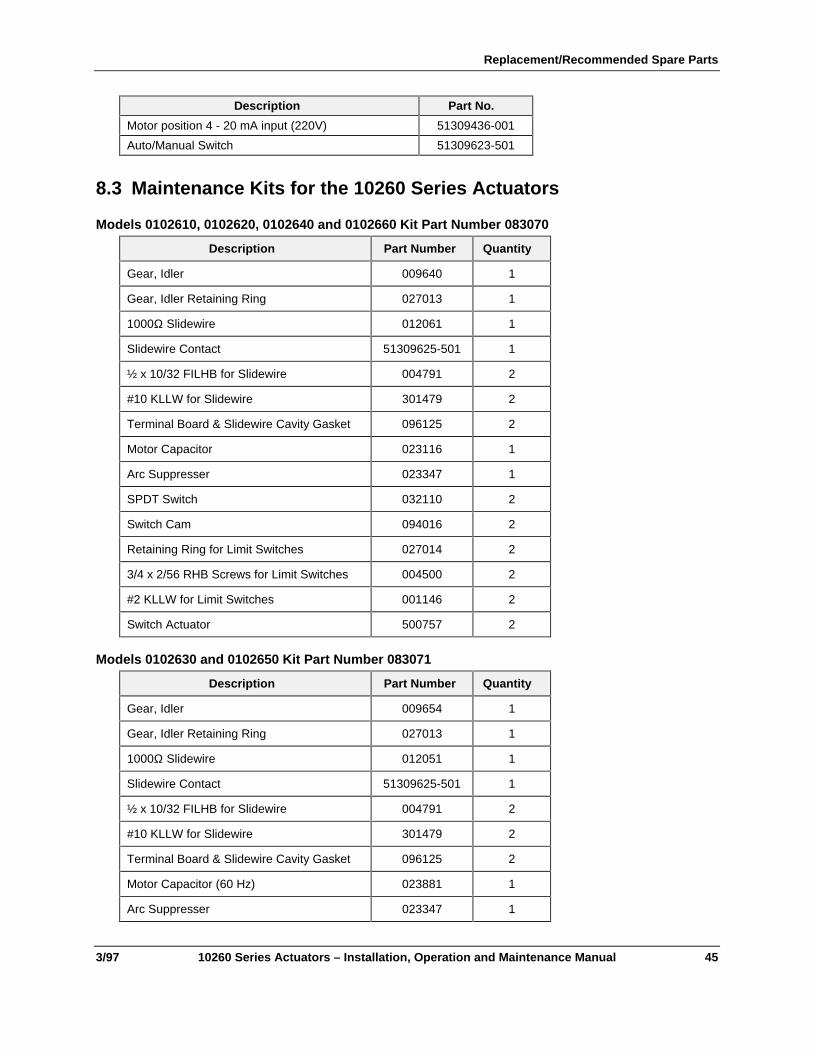
Replacement/Recommended Spare Parts
3/97 10260 Series Actuators – Installation, Operation and Maintenance Manual 45
Description Part No.
Motor position 4 - 20 mA input (220V) 51309436-001
Auto/Manual Switch 51309623-501
8.3 Maintenance Kits for the 10260 Series Actuators
Models 0102610, 0102620, 0102640 and 0102660 Kit Part Number 083070
Description Part Number Quantity
Gear, Idler 009640 1
Gear, Idler Retaining Ring 027013 1
1000Ω Slidewire 012061 1
Slidewire Contact 51309625-501 1
½ x 10/32 FILHB for Slidewire 004791 2
#10 KLLW for Slidewire 301479 2
Terminal Board & Slidewire Cavity Gasket 096125 2
Motor Capacitor 023116 1
Arc Suppresser 023347 1
SPDT Switch 032110 2
Switch Cam 094016 2
Retaining Ring for Limit Switches 027014 2
3/4 x 2/56 RHB Screws for Limit Switches 004500 2
#2 KLLW for Limit Switches 001146 2
Switch Actuator 500757 2
Models 0102630 and 0102650 Kit Part Number 083071
Description Part Number Quantity
Gear, Idler 009654 1
Gear, Idler Retaining Ring 027013 1
1000Ω Slidewire 012051 1
Slidewire Contact 51309625-501 1
½ x 10/32 FILHB for Slidewire 004791 2
#10 KLLW for Slidewire 301479 2
Terminal Board & Slidewire Cavity Gasket 096125 2
Motor Capacitor (60 Hz) 023881 1
Arc Suppresser 023347 1

10260 Series Actuators Installation, Operation and Maintenance Manual
46 10260 Series Actuators – Installation, Operation and Maintenance Manual 3/97
Description Part Number Quantity
SPDT Switch 032110 2
Switch Cam 094016 2
Retaining Ring for Limit Switches 027014 2
3/4 x 2/56 RHB Screws for Limit Switches 004500 2
#2 KLLW for Limit Switches 001146 2
Switch Actuator 500757 2
Models 0102670 Kit Part Number 083072
Description Part Number Quantity
Gear, Idler 009640 1
Gear, Idler Retaining Ring 027013 1
1000Ω Slidewire 012061 1
Slidewire Contact 51309625-501 1
½ x 10/32 FILHB for Slidewire 004791 2
#10 KLLW for Slidewire 301479 2
Terminal Board & Slidewire Cavity Gasket 096125 2
Motor Capacitor 024241 1
Arc Suppresser 023347 1
SPDT Switch 032110 2
Switch Cam 094016 2
Retaining Ring for Limit Switches 027014 2
3/4 x 2/56 RHB Screws for Limit Switches 004500 2
#2 KLLW for Limit Switches 001146 2
Switch Actuator 500757 2
Models 0102680 and 0102690 Kit Part Number 083073
Description Part Number Quantity
Gear, Idler 009641 1
Gear, Idler Retaining Ring 027013 1
1000Ω Slidewire 012061 1
Slidewire Contact 51309625-501 1
½ x 10/32 FILHB for Slidewire 004791 2
#10 KLLW for Slidewire 301479 2
Terminal Board & Slidewire Cavity Gasket 096125 2

Replacement/Recommended Spare Parts
3/97 10260 Series Actuators – Installation, Operation and Maintenance Manual 47
Description Part Number Quantity
Motor Capacitor (60 Hz) 024241 1
Arc Suppresser 023347 1
SPDT Switch 032110 2
Switch Cam 094016 2
Retaining Ring for Limit Switches 027014 2
3/4 x 2/56 RHB Screws for Limit Switches 004500 2
#2 KLLW for Limit Switches 001146 2
Switch Actuator 500757 2
8.4 Linkage Parts
Linkage Kit Part Numbers
Turnbuckle Kit Pipe Kit
Overall linkage length (inches/cm) Overall linkage length (inches/cm)*
up to 75 lb-ft(100 NM)
min max. kit number min. max. pipe size kit number
12 16 083381 24 72 1” 083384
16 20 083382 24 120 1 ½” 083385
20 24 083383 - - - -
Overall linkage length (inches) Overall linkage length (inches)*
150 to 300 lb-ft(200 to 410 NM)
min max. kit number min. max. pipe size kit number
12 16 083381 24 28 1” 083384
16 20 083382 24 84 1 ½” 083385
20 24 083383 24 120 2” 083386
8.5 Feedback AssemblyReplacement /Recommended Spare Parts List
Description Part Number Quantity
0 to 16 VDC Output 205411 1
4 to 20 mA Output 205446 1

10260 Series Actuators Installation, Operation and Maintenance Manual
48 10260 Series Actuators – Installation, Operation and Maintenance Manual 3/97
8.6 Motor Positioner AssemblyDescription Part Number Quantity
CAT/PAT Positioner 120V 070751 1
CAT/PAT Positioner 220V 084733 1
250Ω Resistor 233392 1
Fuse F1, F2 1.6 amp 014239 2
Fuse F3 1.0 amp 014149 1
8.7 Honeywell Actuator Linkage Design Software
Description Part Number
HAL Linkage design Software 51197910-001


Industrial Automation and Control Helping You Control Your WorldHoneywell, Inc.1100 Virginia DriveFort Washington, Pennsylvania 19034