10/22/2015 directhit search - f01. · pdf filecylinder head cover removal ......
TRANSCRIPT

10/22/2015 DirectHit Search
http://www.identifix.com/SearchFixes/Index?ROID=119013645&VID=2189933&VSM=1&LocationId=2#KW=timing+chain&SOption=1&VETId=8&STMode=1… 1/14
TIMING CHAIN REMOVAL/INSTALLA...
< Previous Next >
2007 Mazda3 Engine
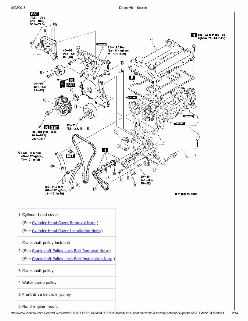
TIMING CHAIN REMOVAL/INSTALLATION [L3 WITH TC]
1. Remove the battery cover.
2. Disconnect the negative battery cable.
3. Remove the under cover and splash shield.
4. Remove the charge air cooler. (See INTAKEAIR SYSTEM REMOVAL/INSTALLATION [L3 WITH TC].)
5. Remove the high pressure fuel pump. (See HIGH PRESSURE FUEL PUMP REMOVAL/INSTALLATION[L3WITH TC].)
6. Remove the ignition coils. (See IGNITION COIL REMOVAL/INSTALLATION[L3 WITH TC].)
7. Disconnect the wiring harness.
8. Remove the ventilation hose.
9. Remove the drive belt. (See DRIVE BELT REMOVAL/INSTALLATION [L3 WITH TC].)
10. Remove the crankshaft position (CKP) sensor. (See CRANKSHAFT POSITION (CKP) SENSORREMOVAL/INSTALLATION[L3 WITH TC].)
11. Remove the P/S oil pump with the hoses and pipes still connected. (See POWER STEERING OIL PUMPREMOVAL/INSTALLATION[L3 WITH TC].)
NOTE:
Position and secure the P/S oil pump out of the way with a rope or wire.
12. Remove in the order indicated in the figure.
13. Install in the reverse order of removal.
14. Start the engine and inspect and adjust the following:
a. Engine oil amount (See ENGINE OIL LEVEL INSPECTION[L3 WITH TC].)
b. Runout and contact of pulley and belt.
c. Ignition timing, idle speed, and idle mixture (CO and HC) verification (See ENGINE TUNEUP[L3 WITH TC].)
10/22/2015 DirectHit Search
http://www.identifix.com/SearchFixes/Index?ROID=119013645&VID=2189933&VSM=1&LocationId=2#KW=timing+chain&SOption=1&VETId=8&STMode=1… 2/14
1 Cylinder head cover
(See Cylinder Head Cover Removal Note.)
(See Cylinder Head Cover Installation Note.)
2
Crankshaft pulley lock bolt
(See Crankshaft Pulley Lock Bolt Removal Note.)
(See Crankshaft Pulley Lock Bolt Installation Note.)
3 Crankshaft pulley
4 Water pump pulley
5 Front drive belt idler pulley
6 No. 3 engine mount

10/22/2015 DirectHit Search
http://www.identifix.com/SearchFixes/Index?ROID=119013645&VID=2189933&VSM=1&LocationId=2#KW=timing+chain&SOption=1&VETId=8&STMode=1… 3/14
(See No.3 Engine Mount Removal Note.)
(See No.3 Engine Mount Installation Note)
7 Engine front cover
(See Engine Front Cover Installation Note.)
8 Front oil seal
(See Front Oil Seal Removal Note.)
(See Front Oil Seal Installation Note.)
9 Chain tensioner
(See Chain Tensioner Removal Note.)
10Tensioner arm
11Chain guide
12Timing chain
(See Timing Chain Installation Note.)
13Oil jet
14Oil pump chain tensioner
15Oil pump chain guide
16Oil pump driven sprocket
(See Oil Pump Driven Sprocket Removal Note.)
(See Oil Pump Driven Sprocket Installation Note.)
17Oil pump chain
18Crankshaft sprocket
19Oil pump drive sprocket
(See Oil Pump Driven Sprocket Installation Note.)
Cylinder Head Cover Removal Note
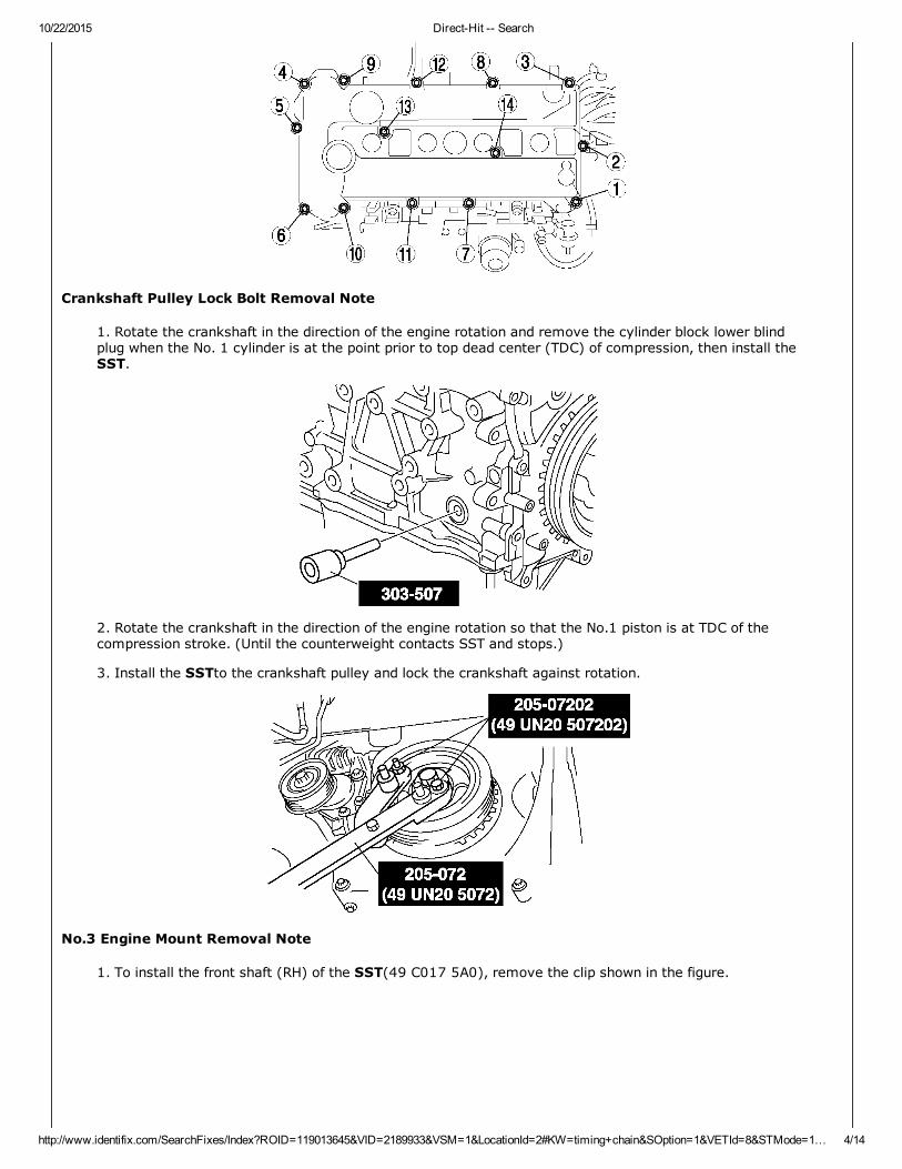
1. Loosen the cylinder head cover bolts in the order shown in the figure.
10/22/2015 DirectHit Search
http://www.identifix.com/SearchFixes/Index?ROID=119013645&VID=2189933&VSM=1&LocationId=2#KW=timing+chain&SOption=1&VETId=8&STMode=1… 4/14
Crankshaft Pulley Lock Bolt Removal Note
1. Rotate the crankshaft in the direction of the engine rotation and remove the cylinder block lower blindplug when the No. 1 cylinder is at the point prior to top dead center (TDC) of compression, then install theSST.
2. Rotate the crankshaft in the direction of the engine rotation so that the No.1 piston is at TDC of thecompression stroke. (Until the counterweight contacts SST and stops.)
3. Install the SSTto the crankshaft pulley and lock the crankshaft against rotation.
No.3 Engine Mount Removal Note
1. To install the front shaft (RH) of the SST(49 C017 5A0), remove the clip shown in the figure.
10/22/2015 DirectHit Search
http://www.identifix.com/SearchFixes/Index?ROID=119013645&VID=2189933&VSM=1&LocationId=2#KW=timing+chain&SOption=1&VETId=8&STMode=1… 5/14
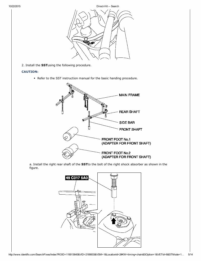
2. Install the SSTusing the following procedure.
CAUTION:
Refer to the SST instruction manual for the basic handing procedure.
a. Install the right rear shaft of the SSTto the bolt of the right shock absorber as shown in thefigure.

10/22/2015 DirectHit Search
http://www.identifix.com/SearchFixes/Index?ROID=119013645&VID=2189933&VSM=1&LocationId=2#KW=timing+chain&SOption=1&VETId=8&STMode=1… 6/14
b. Install the left rear shaft of the SSTto the bolt of the left shock absorber (Identical positionto right side).
c. Install front foot No.2 to the left/right front shaft of the SST, then align the groove of thefront shaft of the SSTwith the folded up part of the vehicle as shown in the figure.
d. Adjust the positions of the SSTside bars so that they are the same height (left and right) andhorizontal.
e. Make sure each joint is securely tightened.
3. Support the engine using the SST.
4. Remove the battery tray bracket, No.4 engine mount rubber and bracket.
Front Oil Seal Removal Note
1. Remove the front oil seal using a flathead screwdriver or similar tool.

10/22/2015 DirectHit Search
http://www.identifix.com/SearchFixes/Index?ROID=119013645&VID=2189933&VSM=1&LocationId=2#KW=timing+chain&SOption=1&VETId=8&STMode=1… 7/14
Chain Tensioner Removal Note
1. Press the timing chain tensioner ratchet to the left using a thin flathead screwdriver (precisionscrewdriver) to unlock the plunger.
2. Slowly press the plunger back in the direction shown in the figure while pressing the ratchet.
3. Release the ratchet with the plunger still pressed down.
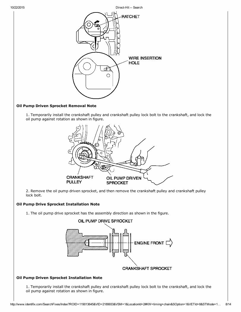
4. Pressin the plunger until the ratchet position is as indicated in the figure, and then insert the wire tolock the plunger.
10/22/2015 DirectHit Search
http://www.identifix.com/SearchFixes/Index?ROID=119013645&VID=2189933&VSM=1&LocationId=2#KW=timing+chain&SOption=1&VETId=8&STMode=1… 8/14
Oil Pump Driven Sprocket Removal Note
1. Temporarily install the crankshaft pulley and crankshaft pulley lock bolt to the crankshaft, and lock theoil pump against rotation as shown in figure.
2. Remove the oil pump driven sprocket, and then remove the crankshaft pulley and crankshaft pulleylock bolt.
Oil Pump Drive Sprocket Installation Note
1. The oil pump drive sprocket has the assembly direction as shown in the figure.
Oil Pump Driven Sprocket Installation Note
1. Temporarily install the crankshaft pulley and crankshaft pulley lock bolt to the crankshaft, and lock theoil pump against rotation as shown in figure.

10/22/2015 DirectHit Search
http://www.identifix.com/SearchFixes/Index?ROID=119013645&VID=2189933&VSM=1&LocationId=2#KW=timing+chain&SOption=1&VETId=8&STMode=1… 9/14
2. Install the oil pump driven sprocket, and then remove the crankshaft pulley and crankshaft pulley lockbolt.
Tightening torque
20—30 N·m {2.1—3.0 kgf·m, 15—22 ft·lbf}
Timing Chain Installation Note
1. Install the SSTto the camshaft as shown in the figure.
2. Install the timing chain.
3. Remove the wire or paper clip from the chain tensioner piston and apply tension to the timing chain.
Front Oil Seal Installation Note
1. Apply clean engine oil to a new front oil seal.
2. Push the front oil seal in the engine front cover by hand.
3. Use the SSTto tap in the front oil seal.

10/22/2015 DirectHit Search
http://www.identifix.com/SearchFixes/Index?ROID=119013645&VID=2189933&VSM=1&LocationId=2#KW=timing+chain&SOption=1&VETId=8&STMode=1… 10/14
Front oil seal pressin amount
0—0.5 mm {0—0.019 in}
Engine Front Cover Installation Note
1. Apply silicone sealant to the engine front cover.
CAUTION:
Install the engine front cover before the applied silicone sealant starts to harden.
Thickness
A: 2.2—3.2 mm {0.087—0.12 in}
B: 1.5—2.5 mm {0.06—0.098 in}
2. Tighten the engine front cover installation bolts in the order shown in the figure.

10/22/2015 DirectHit Search
http://www.identifix.com/SearchFixes/Index?ROID=119013645&VID=2189933&VSM=1&LocationId=2#KW=timing+chain&SOption=1&VETId=8&STMode=1… 11/14
Installation Position Tightening Torque
1―18 8.0—11.5 N·m {82—117 kgf·cm, 71—101 in·lbf}
19―22 40—55 N·m {4.1—5.6 kgf·m, 30—40 ft·lbf}
No.3 Engine Mount Installation Note
1. Tighten the stud bolt of the No.3 engine mount bracket.
Tightening torque 7.0—13 N·m {71.4—132.5 kgf·cm, 62.0—115.0 in·lbf}
NOTE:
Tightening stud bolt when the nut of No.3 engine mount nut is loosened.
2. Handtighten the No.3 engine mount rubber and No.3 engine mount bracket.
3. Tighten the No.3 engine mount bolts and nuts in the order as shown in the figure.

10/22/2015 DirectHit Search
http://www.identifix.com/SearchFixes/Index?ROID=119013645&VID=2189933&VSM=1&LocationId=2#KW=timing+chain&SOption=1&VETId=8&STMode=1… 12/14
Tightening torque
74.5—104.9 {7.6—10.6 kgf·m, 55.0—77.3 ft·lbf}
Crankshaft Pulley Lock Bolt Installation Note
1. Install the SSTto the camshaft as shown in the figure.
2. Verify that the No.1 cylinder is at TDC of the compression stroke. (The position counter weight contactsthe SST.)
3. To position the crankshaft pulley, temporarily tighten it and, using a suitable bolt ( M6 X 1.0 length25—35 mm {0.99—1.3 in}), fix the crankshaft pulley to the engine front cover.
4. Install the SSTsto the crankshaft pulley, lock the crankshaft against rotation, and tighten thecrankshaft pulley lock bolt using the following two steps.

10/22/2015 DirectHit Search
http://www.identifix.com/SearchFixes/Index?ROID=119013645&VID=2189933&VSM=1&LocationId=2#KW=timing+chain&SOption=1&VETId=8&STMode=1… 13/14
Tightening procedure
1st step: 96—104 N·m {9.8—10.6 kgf·m, 70.9—76.7 ft·lbf}
2nd step: 87°—93°
5. Remove the bolt ( M6 X 1.0 length 25—35 mm {0.99—1.3 in}) installed to the crankshaft pulley.
6. Remove the SSTfrom the camshaft.
7. Remove the SSTinstalled in the cylinder block lower blind plug hole.
8. Rotate the crankshaft clockwise two turns and inspect the valve timing.
If not aligned, repeat from Step 1.
9. Install the cylinder block lower blind plug.
Tightening torque
18—22 N·m {1.9—2.2 kgf·m, 14—16 ft·lbf}
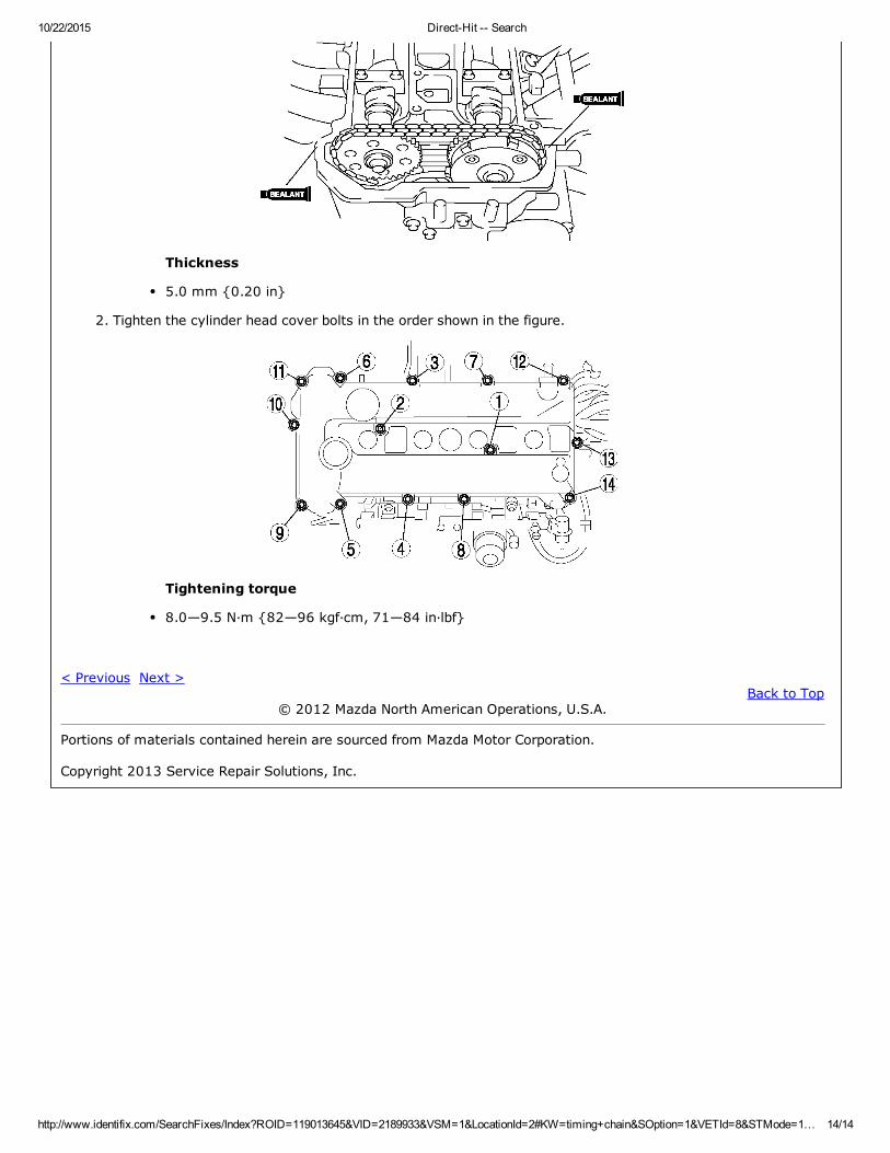
Cylinder Head Cover Installation Note
1. Apply silicone sealant to the areas shown in the figure.
10/22/2015 DirectHit Search
http://www.identifix.com/SearchFixes/Index?ROID=119013645&VID=2189933&VSM=1&LocationId=2#KW=timing+chain&SOption=1&VETId=8&STMode=1… 14/14
Thickness
5.0 mm {0.20 in}
2. Tighten the cylinder head cover bolts in the order shown in the figure.
Tightening torque
8.0—9.5 N·m {82—96 kgf·cm, 71—84 in·lbf}
< Previous Next >Back to Top
© 2012 Mazda North American Operations, U.S.A.
Portions of materials contained herein are sourced from Mazda Motor Corporation.
Copyright 2013 Service Repair Solutions, Inc.