10191: effect of oxygen and heat stable salts on the ... 1 effect of oxygen and heat stable salts on...
TRANSCRIPT

2010
1
EFFECT OF OXYGEN AND HEAT STABLE SALTS ON THE CORROSION OF CARBON STEEL IN MDEA-BASED CO2
CAPTURE PROCESS
Deli Duan1,2, Yoon-Seok Choi1, Srdjan Nešić1,Frederic Vitse
3, Stephen A. Bedell4, Clare Worley4
1Institute for Corrosion and Multiphase Technology, Department of Chemical and Biomolecular Engineering, Ohio University, Athens, OH 45701, USA
2Institute of Metal Research, Chinese Academy of Sciences, Shenyang, 110016, China 3Alstom Power Inc., 1409 Centerpoint Blvd. Knoxville, TN 37932, USA
4
The Dow Chemical Company, 2301 N. Brazosport Blvd., B-1605, Freeport, TX 77541, USA
ABSTRACT
The objective of the present study is to evaluate the corrosion properties of carbon steel in MDEA / H2O / CO2 / O2 / HSSs mixtures related to the CO2 capture process in fossil fuel-fired power plants. Short-term and long-term corrosion tests were performed in 50 wt.% methyldiethanolamine (MDEA) solutions at 50oC under atmospheric pressure with different combinations of CO2, O2 and HSSs (bicine, formate, sulfate). Corrosion behavior of carbon steel was evaluated by using electrochemical methods (LPR, EIS and cyclic polarization), weight loss measurements, and surface analytical techniques (SEM and EDS). The results of short-term corrosion tests indicated that the addition of CO2 in the MDEA systems significantly increased the corrosion rate and changed the corrosion behavior from a passive to active state. However, the corrosion rates of carbon steel did not change significantly with addition of O2 and HSSs. The corrosion rates of carbon steel decreased with time under MDEA/CO2 systems whereas it maintained the initial values throughout the tests in MDEA/CO2/O2 and MDEA/CO2/O2/HSSs environments. The order of the corrosivity was MDEA/CO2/O2/HSS > MDEA/CO2/O2 > MDEA/CO2. The corrosion morphology of carbon steel in MDEA/CO2 systems with O2
and HSSs showed uniform attack with preferential dissolution of ferrite.
Key words: CO2 capture, CO2 corrosion, MDEA, O2
, heat stable salt, carbon steel
INTRODUCTION
Emissions from fossil fuel-fired power plants represent a significant source of carbon dioxide emissions, a known greenhouse gas. To significantly reduce CO2 emissions from power plants, CO2 must be captured, compressed, and transported to a sequestration site. One of the most promising approaches for capturing CO2 from a conventional coal-fired boiler
©2010 by NACE International. Requests for permission to publish this manuscript in any form, in part or in whole, must be in writing to NACEInternational, Publications Division, 1440 South Creek Drive, Houston, Texas 77084. The material presented and the views expressed in this paper aresolely those of the author(s) and are not necessarily endorsed by the Association.
1
Paper No.
10191

2
is the use of an aqueous amine (alkanolamine)-based solution to absorb CO2 from the flue gas stream. In amine-based CO2 capture processes, the amine system is designed to form soluble salts from the reaction of amine with acid gas (CO2) in the absorber, and to reverse the process in the regenerator, releasing the acid gas to the regenerator overhead:1,2
Absorber reactions: R3N + CO2 + H2O → (R3NH)+ + (HCO3)-
Regenerator reactions: [amine + acid → salt] (1)
(R3NH)+ + (HCO3)- + Heat → R3N + CO2 + H2
O [salt + heat → amine + acid gas] (2)
Removing CO2 with alkanolamine-based exhaust gas conditioning solvents poses its own problems, notably corrosion.3 On the basis of plant experiences, corrosion seems to take place in several plant locations including the bottom portion of the absorber, the rich-lean heat exchanger, the regenerator, and the reboiler. Both uniform and localized corrosion such as pitting, galvanic, erosion, stress cracking, and intergranular corrosion have been detected.4,5 Alkanolamines such as monoethanolamine (MEA), diethanolamine (DEA), and methyldiethanolamine (MDEA) are commonly used for CO2 capture processes. The use of primary amines such as MEA leads to a more corrosive environment than secondary (DEA) and tertiary (MDEA) amines because it is a stronger Lewis base than DEA and MDEA, which is the weakest. Both MEA and DEA form carbamate with CO2 while the tertiary amine, MDEA, does not.6 Carbamates have a great impact on the corrosivity of amine solutions.5,7 Thus, MDEA is the most forgiving amine from a corrosion standpoint.6,7 However, minimal information has been reported in the literature concerning the electrochemical behavior and corrosion mechanisms of carbon steel in CO2
-loaded MDEA solutions.
Regardless of amine type for the CO2 capture process, the formation of heat stable salts (HSSs) in amine solutions has long been a problem. HSSs are formed in the presence of acids which are substantially stronger than CO2. These acids can form directly from flue gas components such as SO2 and SO3 or can be formed from amine degradation products. For example, if formic acid is produced, it will react with MDEA to form a formate HSS:
2
Absorber reaction: R3N + HO2CH → (R3NH)+ + (O2CH)-
Regenerator reactions: [amine plus acid → salt] (3)
(R3NH)+ + (O2CH)-
+ Heat → No Change (4)
The HSSs typically promote corrosion in the systems because they lower the pH and increase the conductivity of amine solutions. This can decrease the efficiency of CO2
capture because of the irreversible reaction with the amine.
Many studies have been performed related to corrosion associated with removing acidic gases, usually hydrogen sulfide (H2S) and carbon dioxide (CO2), from natural and refinery gas streams. However, there are significant differences with exhaust gas applications, such as:
8
• Near atmospheric operating pressure • Oxygen-rich environment • Contaminants from products of combustion (NOx, SOx, particulates, etc.)
2

3
These particular conditions involving flue gas can introduce more complicated corrosion problems in alkanolamine systems. However, there is little information about corrosion issues in exhaust gas applications. In this work, tests were designed to simulate corrosion environments in the absorber. Short-term tests were focused on the evaluation of the corrosion behavior of carbon steel under operating conditions in the absorber and identifying the effect of all possible components present in the system. Long-term tests were used to evaluate the corrosion behavior with time and the corrosion mechanism of carbon steel in MDEA/CO2/O2/HSSs mixtures related to the CO2
capture process.
EXPERIMENTAL PROCEDURE
The specimens were made of carbon steel (ASTM(1
) A36) with a chemical composition of 0.23% C, 0.79% Mn, 0.02% P, 0.03% S, 0.29% Cu, 0.20% Si and balance Fe. Carbon steel was chosen as it is generally used in the absorber, lean amine cooler tubes, reflux drum, and regenerator shell. The specimens were ground with 600 grit silicon carbide paper, cleaned with isopropyl alcohol in an ultrasonic bath and dried.
An aqueous solution of MDEA with a concentration of 50% by weight was prepared from a 99% MDEA reagent and DI water. The test solution was purged with 12% CO2 (0.12 bar: CO2 loading= 0.13 mol CO2/mol amine) and/or 6% O2
(0.06 bar) depending on the test conditions. In order to achieve equilibrium for the system, the solution was purged with gases for least 6 hours before the test. The heat stable salts (HSSs) were prepared as a mixture of bicine anion, formate and sulfate which were made up by the dissolution of their acid forms in an aqueous MDEA solution. The total concentration of HSSs was fixed as 15,000 ppm (10,000 ppm bicine + 2818 ppm formic acid + 3002 ppm sulfuric acid).
Corrosion tests were carried out in a 2L glass cell at 50o
C under atmospheric pressure. The setup consists of a: (1) three-electrode corrosion cell (CE: platinum wire, RE: Ag/AgCl electrode); (2) hot plate equipped with temperature controller; (3) gas (nitrogen, oxygen and carbon dioxide) supply set; (4) condenser; (5) potentiostat; and (6) pH meter. The schematic of experimental setup is shown in Figure 1.
FIGURE 1 – Experimental Setup for Corrosion Tests
(1) ASTM International (ASTM), 100 Barr Harbor Dr., West Conshohocken, PA 19428.
3

4
Short-Term Corrosion Experiments
Table 1 and Figure 2 demonstrate the test conditions and procedures for the short-term corrosion test. The test conditions were set in order to investigate the effect of CO2, O2 and HSSs on the corrosion of carbon steel in an aqueous MDEA solution. The corrosion rate was measured using linear polarization resistance (LPR) and electrochemical impedance spectroscopy (EIS) measurements. LPR measurements were performed within ±10 mV with respect to the corrosion potential with a scan rate of 0.166 mV/s. EIS measurements were conducted in the frequency range between 10 kHz and 10 mHz. Sinusoidal voltage of ±10 mV was supplied at the corrosion potential. The cyclic potentiodynamic polarization tests were carried out after conducting LPR and EIS measurements. The specimen was scanned potentiodynamically at a rate of 0.166 mV/s to a potential corresponding to a current density of 10 A/m2
. At this point, the scan direction was reversed. The downscan was continued until the initial corrosion potential.
TABLE 1 TEST CONDITIONS FOR SHORT-TERM CORROSION TESTS
Test condition 1 CS / 50 wt.% MDEA 2 CS / 50 wt.% MDEA / 6% O3
2 CS / 50 wt.% MDEA / 12% CO
4 2
CS / 50 wt.% MDEA / 12% CO2 / 6% O5
2 CS / 50 wt.% MDEA / HSSs
6 CS / 50 wt.% MDEA / 6% O27
/ HSSs CS / 50 wt.% MDEA / 12% CO2
8 / HSSs
CS / 50 wt.% MDEA / 12% CO2 / 6% O2 * HSSs: 10,000 ppm Bicine + 2818 ppm Formic acid + 3002 ppm Sulfuric acid
/ HSSs
CS: carbon steel, MDEA: Methyldiethanolamine
Time
OCP measurement
LPR measurement Cyclic polarization testsMeasure pH
Prepare solution / add gas
Insert steel coupon
EIS measurement
~ 2 hours ~ 10 minutes~ 6 hours ~ 30 minutes ~ 6 hours
FIGURE 2 – Experimental Procedure for Short-Term Corrosion Tests
Long-Term Corrosion Experiments
This part of the study is focused on the evaluation of the corrosion behavior of carbon steel with time in an aqueous MDEA solution. The testing conditions shown in Table 2 were selected from the results of the short term corrosion study. The corrosion properties of carbon steel were evaluated by electrochemical techniques (open-circuit potential (OCP), LPR, EIS measurements), weight loss measurements, and surface analytical techniques (SEM, EDS). In addition, ferrous ion concentrations and solution pH were measured to monitor the water chemistry with time. Figure 3 shows experimental procedures for the long-term corrosion tests.
4

5
TABLE 2 TEST CONDITIONS FOR LONG-TERM CORROSION TESTS
Test condition 1 CS / 50 wt.% MDEA / 12% CO2
2 CS / 50 wt.% MDEA / 12% CO2 / 6% O
3 2
CS / 50 wt.% MDEA / 12% CO2 / 6% O2
/ HSSs
Time
OCP, LPR, EIS measurements
Measure pH
Prepare solution / add gas
Insert steel coupons
Solution sampling for amine concentration
and CO2 loading
OCP, LPR, EIS measurements
1 day
OCP, LPR, EIS measurements
OCP, LPR, EIS measurements
3 day 5 day 7 day
Withdraw steel coupon for
surface analysis
Withdraw steel coupon for
surface analysis
Withdraw steel coupon for
surface analysis
Withdraw steel coupons for
surface analysis and weight loss measurement
Measure pH Measure pH Measure pH Measure pH
Solution sampling for amine concentration, CO2 loading, and Fe2+
concentration
Fe2+ concentration Fe2+ concentration Fe2+ concentration
FIGURE 3 – Experimental Procedures for Long-Term Corrosion Tests
RESULTS Short-Term Corrosion Experiments
Effect of CO2 and O2: The results of LPR, EIS, OCP and pH measurements for 50 wt.% MDEA (MDEA), 50 wt.% MDEA / 6% O2 (MDEA/O2), 50 wt.% MDEA / 12% CO2 (MDEA/CO2), and 50 wt.% MDEA / 12% CO2 / 6% O2 (MDEA/CO2/O2) are described in Figure 4. The polarization resistance values obtained from LPR and EIS were averaged for each condition and represented in reciprocal form. The reciprocal polarization resistance (1/Rp) for MDEA and MDEA/O2 conditions showed very low values with noble OCP values, indicating spontaneous passivation of carbon steel. However, the 1/Rp had a significant increase with adding CO2 into the system. These results indicate that CO2 can obviously increase the system’s corrosivity with the formation of H2CO3 or HCO3
-, which also led to decrease in pH. However, addition of O2 did not change the corrosion rate and OCP in MDEA/CO2
systems.
Figure 5 illustrates the cyclic polarization curves for carbon steel in different test conditions. Carbon steel showed spontaneous passivation without CO2, whereas it presented typical active-passive corrosion behavior with CO2 in MDEA systems. There are no significant shifts of the polarization curves of carbon steel in MDEA/CO2 systems with and without O2; this indicates O2 has little influence on the corrosion behavior of carbon steel in the short-term corrosion tests. In addition, as shown in Figure 5, the reverse polarization curve is on the left of the forward curve for all conditions which demonstrates no pitting tendency for carbon steel in MDEA systems with CO2 and O2.
5

6
(a) (b)
FIGURE 4 – Effect of CO2 and O2 on the Corrosion Properties of Carbon Steel in
Aqueous MDEA Solutions: (a) Inverse of Rp
, (b) OCP and pH
FIGURE 5 – Cyclic Polarization Curves of Carbon Steel in MDEA Systems with CO2 and O
2
Effect of Heat Stable Salts: Figure 6 shows the comparison of the polarization resistance and OCP with / without heat stable salts (HSSs) in MDEA systems. The addition of HSSs slightly increased the corrosion rates of carbon steel in MDEA systems but it didn’t change the corrosion behavior of carbon steel. This indicates that among CO2, O2 and HSSs, CO2
is a primary factor for the corrosion of carbon steel in MDEA systems in that it changes the corrosion behavior from a passive to active state.
MDEA MDEA+O2 MDEA+CO2 MDEA+CO2+O210-10
10-9
10-8
10-7
10-6
10-5
10-4
10-3
10-2
10-1
Conditions
1/R p (
ohm
-1cm
-2)
8.0
8.5
9.0
9.5
10.0
10.5
11.0
11.5
MDEA MDEA+O2 MDEA+CO2 MDEA+CO2+O2
-0.8
-0.7
-0.6
-0.5
-0.4
-0.3
-0.2
-0.1
0.0
OCP pH
Conditions
Pote
ntia
l (V
vs. s
at. A
g/Ag
Cl)
pH
10-6 10-5 10-4 10-3 10-2 10-1 100 101 102
-1.0
-0.5
0.0
0.5
1.0
Pote
ntia
l (V
vs. s
at. A
g/Ag
Cl)
Current density (A/m2)
50% MDEA 50% MDEA / 6% O2
50% MDEA / 12% CO2
50% MDEA / 12% CO2 / 6% O2
6

7
(a) (b)
FIGURE 6 – Effect of HSSs on the Corrosion Properties of Carbon Steel in Aqueous
MDEA Solutions: (a) Inverse of Rp
, (b) OCP
Figure 7 illustrates the effect of HSSs on the polarization behavior of carbon steel in MDEA/CO2 and MDEA/CO2/O2
conditions. In the active region, the cathodic current densities of the systems with HSSs were lower than those of the systems without HSSs with no obvious differences in anodic current densities. Such a difference in the cathodic behavior was probably due to changes in mechanism of reduction of corroding agents in the presence of HSSs. In the passive region, adding HSSs into the system increased the passive current density indicating the presence of HSSs reduced the protection ability of the passive film covering the metal surface. However, the polarization behavior in the transpassive region was almost identical with no pitting tendency.
(a) (b)
FIGURE 7 – Cyclic Polarization Curves of Carbon Steel in MDEA Systems with HSSs: (a)
MDEA/CO2, (b) MDEA/CO2/O
2
MDEA MDEA+O2 MDEA+CO2 MDEA+CO2+O210-10
10-9
10-8
10-7
10-6
10-5
10-4
10-3
10-2
10-1
1/R p (
ohm
-1cm
-2)
Conditions
Without HSSs With HSSs
MDEA MDEA+O2 MDEA+CO2 MDEA+CO2+O2-0.9
-0.8
-0.7
-0.6
-0.5
-0.4
-0.3
-0.2
-0.1
0.0
Pote
ntia
l (V
vs. s
at. A
g/Ag
Cl)
Conditions
Without HSSs With HSSs
10-3 10-2 10-1 100 101 102
-1.0
-0.5
0.0
0.5
1.0
Pote
ntia
l (V
vs. s
at. A
g/Ag
Cl)
Current density (A/m2)
50% MDEA / 12% CO2
50% MDEA / 12% CO2 / HSSs
10-3 10-2 10-1 100 101 102
-1.0
-0.5
0.0
0.5
1.0
Pote
ntia
l (V
vs. s
at. A
g/Ag
Cl)
Current density (A/m2)
50% MDEA / 12% CO2 / 6% O2
50% MDEA / 12% CO2 / 6% O2 / HSSs
7

8
Long-Term Corrosion Experiments
Figure 8 shows the variations of polarization resistance and OCP with time for 50 wt.% MDEA / 12% CO2 (MDEA/CO2), 50 wt.% MDEA / 12% CO2 / 6% O2 (MDEA/CO2/O2) and 50 wt.% MDEA / 12% CO2 / 6% O2 / HSSs (MDEA/CO2/O2/HSSs). For all three conditions, the OCP changed within an active potential region during 7 days, and there is little difference in each condition. However, as shown in Figure 8 (a), the corrosion rate decreased with time in MDEA/CO2 condition whereas it maintained the initial values throughout the test periods in MDEA/CO2/O2 and MDEA/CO2/O2/HSSs conditions. The relative corrosivity of systems can be ranked as: MDEA/CO2/O2/HSS > MDEA/CO2/O2 > MDEA/CO2 with MDEA/CO2
(least corrosive).
(a) (b)
Figure 8: Variations of Polarization Resistance (a) and OCP (b) of Carbon Steel in MDEA
Systems with Different Test Conditions
The results of pH and ferrous ion concentration measurements in MDEA systems are shown in Figure 9. The solution pHs decreased after 24 hours for all conditions and stabilized at 8.84 (MDEA/CO2), 9.00 (MDEA/CO2/O2), and 8.91 (MDEA/CO2/O2/HSSs). However, as shown in Figure 8 (a) and Figure 9 (a), there is no relationship between the corrosion rate and the solution pH for all conditions. The ferrous ion concentrations increased with time for MDEA/CO2/O2 and MDEA/CO2/O2/HSSs systems due to the continuous anodic dissolution of carbon steel with time. For the MDEA/CO2
system, ferrous ion concentrations increased slowly up to 5 days and it remained constant for up to 7 days.
Figure 10 shows the variation of the corrosion rates with time obtained from weight loss measurements for MDEA/CO2, MDEA/CO2/O2 and MDEA/CO2/O2/HSS conditions. The corrosion rates measured by weight loss have a similar trend with the results of electrochemical tests. Note that the corrosion rate obviously decreased from 0.21 to 0.08 mm/y in MDEA/CO2, whereas it slightly changed from 0.25 to 0.20 mm/y in MDEA/CO2/O2 and from 0.43 to 0.41 in MDEA/CO2/O2
/HSSs over 7 days.
0 24 48 72 96 120 144 16810-4
10-3
10-2
1/R p (
ohm
-1cm
-2)
Time (hr)
MDEA/ CO2 MDEA/ CO2 / O2
MDEA/ CO2 / O2 / HSSs
0 24 48 72 96 120 144 168-815
-810
-805
-800
-795
-790
-785
Pote
ntia
l (V
vs. s
at. A
g/Ag
Cl)
Time (hr)
MDEA/ CO2 MDEA/ CO2 / O2
MDEA/ CO2 / O2 / HSSs
8

9
FIGURE 9 – Variations of MDEA Solution pH (a) and Ferrous Ion Concentrations (b) with
Different Test Conditions
FIGURE 10 – Variation of Corrosion Rates of Carbon Steel with Time Measured from
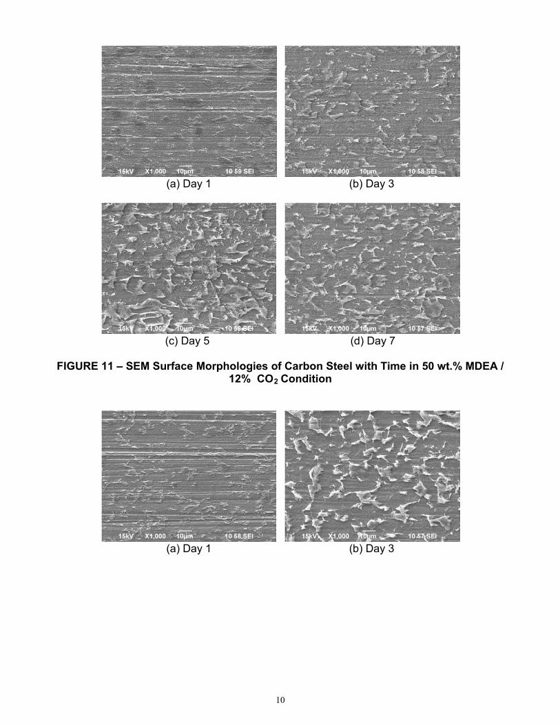
Weight Loss Measurements in MDEA Systems Figures 11 through 13 show the SEM images of the corroded surface of the samples after 1,
3, 5 and 7 days in MDEA systems with different test conditions. It can be seen that there are two distinct areas: one presenting dark color and other showing bright color which grows with time. Figure 14 shows a microstructure of A36 carbon steel which presented typical ferritic-pearlitic (F/P) microstructure. Based on the microstructure shown in Figure 14, it can be known that the dark and the bright regions in corroded surfaces represent ferrite phase and pearlite phases, respectively. Figure 15 shows EDS spectra of the selected parts of the sample after 7 days in MDEA/CO2/O2/HSSs system. More carbon content was detected in pearlite region than ferrite region. This indicates that a preferential dissolution of ferrite into Fe2+ took place and that only iron carbide (Fe3C) from the pearlite was left on the steel surface.9 In addition, more Fe3
C accumulated on the steel surface as increasing the corrosivity of the MDEA solutions.
0 24 48 72 96 120 144 1688.80
8.85
8.90
8.95
9.00
9.05
9.10
pH
Time (hr)
MDEA/ CO2 MDEA/ CO2 / O2
MDEA/ CO2 / O2 / HSSs
0 24 48 72 96 120 144 1680
50
100
150
200
250
300
Fe2+
con
cent
ratio
n (p
pm)
Time (hr)
MDEA/ CO2 MDEA/ CO2 / O2
MDEA/ CO2 / O2 / HSSs
0 24 48 72 96 120 144 1680.0
0.1
0.2
0.3
0.4
0.5
0.6
Corro
sion
rate
(mm
/y)
Time (hr)
MDEA/CO2
MDEA/CO2/O2
MDEA/CO2/O2/HSS
9
10
(a) Day 1 (b) Day 3
(c) Day 5 (d) Day 7
FIGURE 11 – SEM Surface Morphologies of Carbon Steel with Time in 50 wt.% MDEA /
12% CO2
Condition
(a) Day 1 (b) Day 3
10

11
(c) Day 5 (d) Day 7
FIGURE 12 – SEM Surface Morphologies of Carbon Steel with Time in 50 wt.% MDEA /
12% CO2 / 6% O2
Condition
(a) Day 1 (b) Day 3
(c) Day 5 (d) Day 7
FIGURE 13 – SEM Surface Morphologies of Carbon Steel with Time in 50 wt.% MDEA /
12% CO2 / 6% O2
/ HSSs Condition
11

12
FIGURE 14 – Microstructure of A36 Carbon Steel
(a) (b)
FIGURE 15 – Results of EDS Analyses for Corroded Sample after 7 Days in 50 wt.%
MDEA / 12% CO2 / 6% O2
/ HSSs: (a) Pearlite Region and (b) Ferrite Region
As shown in Figure 8 (a) and Figure 10, the corrosion rates of carbon steel in MDEA/CO2 system decreased with time. However, SEM and EDS analyses of the samples showed no indication of the formation of a protective scale on the sample surface. Instead, less preferential dissolution of ferrite and accumulation of carbides on the corroded surfaces after 7 days, compared with MDEA/CO2/O2 and MDEA/CO2/O2/HSS systems were observed. This can introduce a hypothesis that a very thin FeCO3 film may form on the surface and act as a diffusion barrier. However, when O2
is dissolved into the MDEA solutions, another cathodic reaction became available to oxidize the iron according to the following reaction:
O2 + 2H2O + 4e- → 4OH-
(5)
This additional reduction reaction resulted in a greater rate of iron dissolution and an acceleration of the corrosion process for MDEA/CO2/O2 systems.
12

13
When HSSs were added into MDEA/CO2/O2 systems, the corrosion rates evidently increased at the initial stage and changed slightly with time as shown in Figure 8 (a) and Figure 10. In the present study, formate, sulfate and bicine were chosen as HSSs and added in the MDEA systems. Formate and sulfate increase the corrosion rate of carbon steel by increasing the reduction rate of the oxidizing agent10, whereas bicine participates in the corrosion process as a chelator due to its high affinity toward iron.11 Therefore, the addition of HSSs in the MDEA/CO2/O2
systems increased the corrosion rates of carbon steel by accelerating both the anodic and the cathodic reactions.
CONCLUSIONS
• The addition of CO2 in the MDEA systems significantly increased the corrosion rates and changed the corrosion behavior from passive to active state. However, the corrosion rates of carbon steel did not significantly change upon addition of O2
• No pitting trend was observed from cyclic polarization curves in MDEA systems with CO
and HSSs in the short-term corrosion tests.
2, O2• The corrosion rates of carbon steel decreased with time in MDEA/CO
and HSSs. 2 condition
whereas it maintained the initial values throughout the test periods in MDEA/CO2/O2 and MDEA/CO2/O2
• The relative corrosivity of systems was ranked as: MDEA/CO/HSSs conditions.
2/O2/HSS > MDEA/CO2/O2 > MDEA/CO2
• The presence of O.
2 in the MDEA/CO2 systems accelerated the corrosion process by addition of the O2
• The corrosion morphologies of carbon steel in MDEA/CO
reduction reaction, whereas HSSs increased both anodic and cathodic reactions for the corrosion of carbon steel.
2 systems with O2
and HSSs showed uniform attack with preferential dissolution of ferrite.
ACKNOWLEDGMENTS
The authors would like to acknowledge the financial support from Alstom Power Inc. to the Institute for Corrosion and Multiphase Technology at Ohio University.
REFERENCES
1. R.B. Nielsen, K.R.Lewis, J.G. McCullough, and D.A. Hansen, “Controlling Corrosion in
Amine Treating Plants,” Proc. Laurance Reid Gas Cond. Conf. 45th
2. A.L. Cummings, G.D. Smith, and D.K. Nelsen, “Advances in Amine Reclaiming- Why There’s No Excuse to Operate a Dirty Amine System,” Proc. Laurance Reid Gas Cond. Conf. 57
, p. 182 (1995)
th,
3. M.R. Khorrami, K. Raeissi, H. Shahban, M.A. Torkan, and A. Saatchi, Corrosion (February 2008), p. 124
p. 227 (2007)
4. A. Veawab, P. Tontiwachwuthikul, and A. Chakma, Ind. Eng. Chem. Res. (October 1999), p. 3917
5. M.S. DuPart, T.R. Bacon, and D.J. Edwards, Hydrocarbon Processing (April 1993), p. 75 6. M.S. DuPart, T.R. Bacon, and D.J. Edwards, Hydrocarbon Processing (May 1993), p. 89 7. X.-P. Guo, and Y. Tomoe, Corrosion Science (July 1999), p. 1391 8. I.R. Soosaiprakasam and A. Veawab, International Journal of Greenhouse Gas Control
(October 2008), p. 553
13

14
9. J.L. Mora-Mendoza and S. Turgoose, Corrosion Science (June 2002), p. 1223 10. W. Tanthapanichakoon and A. Veawab, Ind. Eng. Chem. Res. (April 2006), p. 2586 11. S.F. Bosen and S.A. Bedell, “The Relevance of Bicine in the Corrosion of Amine Gas
Treating Plants”, CORROSION/2004, Paper No. 04481, NACE (2004)
14