100-ton & 200-ton hydraulic puller systems - posi lock lock 100 and 200 product... · 2 posi...
TRANSCRIPT

1
100-TON & 200-TONHydraulic Puller Systems
INSTRUCTION & PARTS SHEETIMPORTANT: READ CAREFULLY!
IMPORTANT RECEIVING INSTRUCTIONS:Visually inspect all components for shipping damage. Shipping damage is not covered by warranty. If shipping damage is found notify the carrier at once. The carrier is responsible for all repair and replacement costs resulting from damage in shipment.
SAFETY FIRST: It is impossible to predict the exact force needed for every pulling situation. The amount of press-fit and force of removal can vary greatly between jobs. The set-up requirements along with the size, shape and condition of the parts being pulled are all variables which must be considered. Remember that a significant amount of force can be exerted with a puller. Respect this force and always observe safety precautions. Failure to comply with the following cautions and warnings could cause equipment damage or personal injury.
WARNING: DO NOT touch or handle hydraulic hoses or fittings with pressure in the system. Escaping oil under pressure may cause serious injury. If oil is injected under the skin see a doctor immediately.
DO NOT make any electrical adjustments with electrical power active in the system.
DO NOT make or break any hydraulic connections with pressure in the system.
DO NOT overload the equipment. Use the right size puller.
DO NOT stand on, under or near the puller while in use. Keep hands, feet and clothing away from moving parts.
To avoid personal injury and equipment damage, make sure all hydraulic components withstand the maximum hydraulic pressure of 700 bar (10,000 psi).
Make sure all system components are protected from external sources of damage, such as excessive heat, flame, moving machine parts, sharp edges and corrosive chemicals.
Always check to ensure that all cylinders and components are securely fastened.
IMPORTANT: Inspect puller for dents, cracks, or excessive wear before each use. Immediately replace worn or damaged parts.
It is recommended to use 3-jaw puller whenever possible for a more secure grip, a more even pulling force and better stability.
Cover application with a protective blanket before applying force. Since high force is applied on the part being pulled, breakage may occur and user may be exposed to flying debris.
Use hydraulic gauges in each hydraulic system to indicate safe operating loads.
Apply force gradually. Be sure the puller is square with the component to be pulled.
Wear safety glasses or other approved eye protection.
Keep hands away from possible pinching points.
Always make sure the puller is aligned with the shaft.
Select the appropriate ram extender for each application.
Always place the puller in the lowest position and remove ram extenders while transporting.
Keep slide rollers and mast clean and lubricated.
Always keep puller hoist vertical and the control valve closed when not adjusting vertical position.
A small amount of oil seepage is normal from breather vent on hoist cylinder.
Use only genuine POSI LOCK parts and endorsed hydraulic components.
CAUTION: Make sure that all items being pulled are supported by a means other than the puller. When using a puller in excess of 50 pounds, support puller by other means than a single person. Do not use the puller for lifting or supporting objects.
Avoid sharp bends and kinks in hoses as they may lead to premature hose failure. Inspect hoses and fittings for leaks or damaged areas. Immediately discard and replace damaged components.
!
!
!

2
POSI LOCK® 100-TON & 200-TON Hydraulic Puller Systems
Instructions applicable to part numbers described below:
Portable 100-Ton Hydraulic Puller Systems
Model Number
Capacity
Tons (kN)
Number of Jaws
Dimensions
Weight
lbs. (kg)
Spread
in. (mm)
Overall Length
in. (mm)
Reach
in. (mm)
Jaw Length
in. (mm)
Jaw Tip Width
in. (mm)
Tip Clearance
in. (mm)
Tip Depth
in. (mm)
Single Acting
PH-102T100 tons
(890 kN)2
7.5 to 70 in.
(191 to 1778 mm)
77 in.
(1956 mm)
50 in.
(1270 mm)
53 in.
(1346 mm)
1.25 in.
(32 mm)
3.5 in.
(89 mm)
3.5 in.
(89 mm)
1700 lbs.
(771 kg)
PH-100T100 tons
(890 kN)3
7.5 to 70 in.
(191 to 1778 mm)
77 in.
(1956 mm)
50 in.
(1270 mm)
53 in.
(1346 mm)
1.25 in.
(32 mm)
3.5 in.
(89 mm)
3.5 in.
(89 mm)
1950 lbs.
(885 kg)
PH-123T100 tons
(890 kN)2/3
7.5 to 70 in.
(191 to 1778 mm)
77 in.
(1956 mm)
50 in.
(1270 mm)
53 in.
(1346 mm)
1.25 in.
(32 mm)
3.5 in.
(89 mm)
3.5 in.
(89 mm)
2000 lbs.
(907 kg)
Single Acting Vertical
PH-102TV
100 tons
(890 kN)2
7.5 to 70 in.
(191 to 1778 mm)
77 in.
(1956 mm)
50 in.
(1270 mm)
53 in.
(1346 mm)
1.25 in.
(32 mm)
3.5 in.
(89 mm)
3.5 in.
(89 mm)
1800 lbs.
(816 kg)
Double Acting
PH-102TDA
100 tons
(890 kN)2
7.5 to 70 in.
(191 to 1778 mm)
77 in.
(1956 mm)
50 in.
(1270 mm)
53 in.
(1346 mm)
1.25 in.
(32 mm)
3.5 in.
(89 mm)
3.5 in.
(89 mm)
1800 lbs.
(816 kg)
PH-100TDA
100 tons
(890 kN)3
7.5 to 70 in.
(191 to 1778 mm)
77 in.
(1956 mm)
50 in.
(1270 mm)
53 in.
(1346 mm)
1.25 in.
(32 mm)
3.5 in.
(89 mm)
3.5 in.
(89 mm)
2050 lbs.
(930 kg)
PH-123TDA
100 tons
(890 kN)2/3
7.5 to 70 in.
(191 to 1778 mm)
77 in.
(1956 mm)
50 in.
(1270 mm)
53 in.
(1346 mm)
1.25 in.
(32 mm)
3.5 in.
(89 mm)
3.5 in.
(89 mm)
2100 lbs.
(953 kg)
Double Acting Vertical
PH-102DATV
100 tons
(890 kN)2
7.5 to 70 in.
(191 to 1778 mm)
77 in.
(1956 mm)
50 in.
(1270 mm)
53 in.
(1346 mm)
1.25 in.
(32 mm)
3.5 in.
(89 mm)
3.5 in.
(89 mm)
1800 lbs.
(816 kg)
200-Ton Hydraulic Puller System
Model Number
Capacity
Tons (kN)
Number of Jaws
Dimensions
Weight
lbs. (kg)
Spread
in. (mm)
Overall Length
in. (mm)
Reach
in. (mm)
Jaw Length
in. (mm)
Jaw Tip Width
in. (mm)
Tip Clearance
in. (mm)
Tip Depth
in. (mm)
PH-200T200 tons
(1779 kN)4
8 to 70 in.
(203 to 1778 mm)
78.5 in.
(1994 mm)
48 in.
(1219 mm)
53 in.
(1346 mm)
1.25 in.
(32 mm)
3.5 in.
(89 mm)
3.5 in.
(89 mm)
4150 lbs.
(1882 kg)
A
A
B
B
C
C
D E F G
D E F G
max. 66.54 in. (1690 mm)
min. 26.50 in. (673 mm)
77.95 in. (1980 mm)
40.
98 in
. (10
41 m
m)
A
D
E
F
B
C
G
Diagram of a PH-102T
Top view

3
POSI LOCK® 100-TON & 200-TON Hydraulic Puller Systems
Overview
A.B.C.D.E.F.G.H. I.J.K.
JawJaw TipCagePushing AdaptorCage CylinderPushing CylinderControl ValvesHoist CylinderMastBaseCasters
A
D
B
C
CGG
E
F A B
I
H
JK
J
Diagram of a PH-102T
Top view Side view

4
POSI LOCK® 100-TON & 200-TON Hydraulic Puller Systems
Pushers | Jaw TipsPUSHERS:Included with the 100-Ton pullers are THREE pushers and a coupler. String 2 pushers together to increase the reach of the ram. Using a variety of combinations may be necessary to complete the pull of a deeply set gear or bearing.
Included with the 200-Ton puller are FOUR pushers. The diameters are 4 inches. The 200-T does not include a coupler.
Coupler*Not included with the 200-Ton.
JAW TIPS: 3 jaw tip sizes are available for 100 and 200 Ton puller models. • HT-1180: standard with all models.• HT-1180A: optional, for operations with limited space constraints. • HT-1180S: optional, for operations with limited space constraints.
39.0
0
*Included with 200-Ton only.
4
HT-1180S
HT-1180A
HT-1180*
0.0
0.5
1.0
1.5
2.0
2.5
3.0
3.5
4.0
4.5
0.0 in.0.51.01.52.02.53.03.54.04.55.05.56.06.57.07.58.08.59.0
*Tip widths are 3 inches thick.
3.52
4
HT-1164
HT-1163
HT-1162

5
ADJUSTMENTS:RAISING THE PULLER:1. Place cylinder control valve lever in “Hoist Oil Supply” position. 2. Raise puller by placing remote jog switch in “On” position and opening the puller hoist vertical control valve. 3. Release remote jog switch. Close vertical control valve after reaching desired height.
LOWERING THE PULLER:1. Place cylinder control valve lever in “Hoist Lower” position. 2. Lower puller by turning puller hoist vertical control valve counterclockwise. 3. Close vertical control valve after reaching desired height.
NOTE:HOIST TRAVEL SPEED:The restrictor valve, located at the top of the hoist cylinder, is used to control the rate of puller descent. This valve should be set at the desired rate and locked in place using the nut on the valve shaft.
An appropriate starting point is one full turn from the closed position. This valve is a one-way restrictor only and does not affect the rate at which the puller is raised.
POSI LOCK® 100-TON & 200-TON Hydraulic Puller SystemsAssembly | Adjustments
ASSEMBLY:1. Ensure that shipping crate firmly rests on level ground in upright position.2. Open small side panel and confirm that puller is resting firmly in upright position in the create.3. Remove remainder of plywood.4. Inspect puller for any damage that may have been caused by shipping.5. Save bolts that were used to brace the cart. These will be used for securing the included cart wheels to the cart.6. Inspect hoses for proper ratings. Connect the 10,000 psi hose to the port marked “10,000 psi only” on the puller and the pressurized port on the pump. Connect hose with the lower pressure rating to the return port on puller and pump.7. Fill reservoir of pump with pump manufacturer specified oil. See pump or cylinder manual for details.
Jaw guide moved 1 bolt hole OUT to increase spread.
CHANGING THE JAW SPREAD:If opening/closing the jaws using the standard cage setting does not provide enough spread or does not provide enough closure, use the following adjustments to achieve the maximum and minimum spreads.
1. Support the jaws.2. Remove 6 cap screws, lock washers and nuts on 1 jaw guide at a time. 3. Slide jaw guide inward/outward on cage 1 bolt hole. 4. Replace 4 cap screws, lock washer, and nuts and tighten appropriately. 5. Reverse this process to return to standard jaw spread.
Jaw guide moved 1 bolt hole IN to decrease spread.
Default jaw guide position when puller is shipped.

6
ADJUSTING JAW TIPS:1. Adjust jaw tips by turning 1 ¼” cap screw.
NOTE: Always use maximum pulling surface of jaw. To angle tip inward, turn cap screw clockwise. To angle tip outward, turn cap screw counterclockwise. Before pulling, always make certain machined caps are properly fitted to curved surface.
Incorrect IncorrectCorrect Alignment
POSI LOCK® 100-TON & 200-TON Hydraulic Puller Systems
Adjustments (continued) | Removing puller from cart
ADJUSTING SLIDE ROLLERS:1. Lower slide and puller assembly until it rests solidly on base.2. Loosen 5/8” hex bolt.3. Move roller using eye bolts on each side of roller.4. Adjust roller until equal spacing is obtained between mast and slide tube on both roller side and opposite side.5. Tighten locking nut on eye bolt.6. Tighten 5/8” hex bolt.
100-TON:REMOVING PULLER FROM THE CART:1. Support puller weight using lifting brackets provided. 2. Close puller hoist vertical control valve.3. Disconnect puller hoist hose coupler at control panel. 4. Remove 2 of the ½” bolts which fasten locking plate to the puller lift bracket.5. Remove puller from cart by rotating cart while keeping puller stationary.
200-TON:REMOVING PULLER FROM THE CART:1. Support puller weight using lifting brackets provided. 2. Close puller hoist vertical control valve.3. Disconnect puller hoist hose coupler at control panel. 4. On each slide, remove the top and bottom ½” bolts. Do this on both the left and right slide, removing a total of 4 bolts. 5. While keeping the puller supported and balanced, remove from the cart by moving the puller forward.

7
RETRACTING CYLINDER:I. Place cylinder control valve in the “Retract” position. II. Activate pump with jog switch.
POSI LOCK® 100-TON & 200-TON Hydraulic Puller SystemsSet-up | Pulling an object
SET-UP:1. Transport the puller by use of the puller cart of forklift.2. Line the puller up to the workpiece. 3. Open the jaws.
OPENING THE JAWS:I. Place cylinder control valve lever in “Oil Supply” position. II. Place cage control lever in “Jaw Open” position and activate pump by pushing remote switch to the “On” position to open jaws to the desired spread.
CLOSING THE JAWS:I. Place cylinder control valve lever in “Oil Supply” position. II. Place cage control lever in “Jaw Closed” position and activate pump by pushing remote switch to the “On” position to close jaws to the desired spread or for clamping.
EXTENDING CYLINDER:I. Place cylinder control valve in “Extend” position.II. Activate pump with jog switch.
7. Adjust the jaw tips appropriately. See ADJUSTING JAW TIPS on page 4.
4. Position the workpiece to be removed in between the jaws. 5. Continue to adjust the height until the workpiece and extending cylinder are aligned. See RAISING THE PULLER on page 3. 6. Close the jaws.
PULLING AN OBJECT:1. Extend the cylinder ram towards the workpiece until there is contact.
2. Continue to extend the ram. The workpiece will begin to move gradually off the shaft. 3. Retract the cylinder.4. Completely remove the workpiece.
NOTE: On a single acting cylinder the cylinder ram will retract without activating the pump.
OPERATION IMPORTANT: Hydraulic power is one of the safest methods for applying force when used correctly. Be sure to read all instructions, warnings and cautions carefully.
Follow all safety precautions to avoid personal injury or property damage during system operation. Posi Lock cannot be responsible for damage or injury resulting from unsafe use of product, lack of maintenance or incorrect product and/or system operation.
It is important that the operator has a full understanding of all the instructions, warnings, cautions and safety regulations before starting to operate equipment. When in doubt contact Posi Lock at +1-701-797-2600.
MAINTENANCE: Always clean the puller after use and store in a clean, dry place.
!
!

8
2. Remove the jaw on the left from the 2-jaw position.
1. Starting in a 2-jaw configuration, move the cage cylinder from the 2-jaw position to the 3-jaw position.
POSI LOCK® 100-TON & 200-TON Hydraulic Puller Systems
PH-123T Transformation

9
POSI LOCK® 100-TON & 200-TON Hydraulic Puller Systems
PH-123T Transformation (continued)
3. Place the jaw into the lower 3-jaw position.
4. Place jaw from the left 2-jaw position into upper 3-jaw position to complete the transformation.

10
9
100 Ton Spread Range Diagram
SPREAD RANGE DIAGRAM:Use the diagram to determine the limitations of the jaw-opening. Spread ranges apply to all POSI LOCK 100-Ton and 200-Ton hydraulic puller systems. Gears, pulleys, wheels, sleeves, and other press fit parts must fit within these limitations.
POSI LOCK® 100-TON & 200-TON Hydraulic Puller Systems
Spread Range

11
POSI LOCK® 100-TON & 200-TON Hydraulic Puller Systems
Schematics | PH-100T | PH-123T

12
POSI LOCK® 100-TON & 200-TON Hydraulic Puller Systems
Hydraulic Fittings | PH-100T | PH123T
Hydraulic Fittings for 3 Jaw 100-Ton PullersSYM PART # DESC. QTY
A HT-1123 3/8 Male NPTF x 3/8 Male 37˚ 5
B HT-1124 3/8 Male NPTF x 3/8 Male 37 NPTF 1
C HT-1125 3/8 Male NPTF x 3/8 Female NPTF 3
D HT-1126 3/8 Female NPTF Tee 1
E HT-1134 3/8 Male NPTF x 1/4 Male 37˚ 7
G HT-1128 3/8 Male NPTF x 3/8 Female 37˚ 1
H HT-1129 3/8 Male 37˚ Cross 1
I HT-1113 3/8 Male NPTF x 3/8 Female NPTF 2000 PSI Relief 1
J HT-1130 3/8 Male NPTF x 3/8 Female NPTF x 3/8 Female NPTF 2
K HT-1131 3/8 Male NPTF x 3/8 37˚ 2
N HT-1001 3/8 Male NPTF x 3/8 Female NPTF x 3/8 Female NPTF 1
O HT-1002 3/8 Male NPTF x 3/8 Male NPTF 1
P HT-1003 3/8 Male NPTF x 3/8 37˚ 4
Q HT-1004 3/8 Male NPTF x 3/8 Female NPTF 1
R HT-1011 3/8 Female NPTF x 3/8 Female NPTF 1
S HT-1191 3/8 Male NPTF x 3/8 Male Barbed 2
U HT-1154 3/8 Male NPFT Vent 1
V HT-1006 3/8 Female NPTF x 3/4 BOSS 1
W HT-1013 3/8 Male 37˚ x 3/8 Female 37˚ 3
X HT-1014 3/8 Male NPTF x 3/8 Female NPTF 2
Y HT-1134A 3/8 Male NPTF x 1/4 Male 37˚ 2
Z HT-1134B 3/8 Male NPTF x 1/4 Male 37˚ 1

13
POSI LOCK® 100-TON & 200-TON Hydraulic Puller Systems
Hydraulic Hoses and Components | PH-100T | PH123T
Hydraulic Hoses and Components for 3 Jaw 100-Ton Pullers
SYM PART # DESC. QTY
AA PH10010 100-Ton Cylinder 1
BB HT-1103 3-Ton Cylinder 3
CC HT-VC4 4-Way Valve 1
DD HT-1114 3 Section Flow Divider 1
EE FHCH-38M Male Coupler 3
FF HT-VC20 4-Way Closed Center Valve 1
GG HT-V82 Needle Valve 1
HH HT-1121 1-Way Valve 1
II HT-1117 Hoist Cylinder 1
KK HT-GA3 Gauge Adaptor 1
LL PGB254TLM 10,000 PSI Gauge 1
MM PH-2022 Pump 1
NN HT-1135 16” 10,000 PSI Hose 1
QQ HT-1139 33” Hose 2*
RR FHCH-38F Female Coupler 3
SS HT-1140 44” Hose 1**
TT HT-1141 21” Hose 1
UU HT-1142A 15” Hose 2
WW HT-1005 30” Hose 1
AA1 PH-927 10’ 10,000 PSI Hose 1
AA2 HT-1190 10’ Return Hose 1
ST-1 HT-ST1 Steel Line 1
ST-2 HT-ST2 Steel Line 1
ST-3 HT-ST3 Steel Line 1
ST-4 HT-ST4 Steel Line 1
SPECIAL NOTES:* 1- 33” hose is included for the 2/3 jaw combination puller.** 2- 44” hoses are included with the 2/3 jaw combination puller.

14
POSI LOCK® 100-TON & 200-TON Hydraulic Puller Systems
Schematics | PH-102T

15
POSI LOCK® 100-TON & 200-TON Hydraulic Puller Systems
Hydraulic Fittings, Hoses and Components | PH-102T
Hydraulic Fittings for 2 Jaw PullersSYM PART # DESC. QTY
A HT-1123 3/8 Male NPTF x 3/8 Male 37˚ 5
B HT-1124 3/8 Male NPTF x 3/8 Male 37 NPTF 1
C HT-1125 3/8 Male NPTF x 3/8 Female NPTF 3
D HT-1126 3/8 Female NPTF Tee 1
E HT-1134 3/8 Male NPTF x 1/4 Male 37˚ 7
F HT-1127 3/8 Male 37˚x 3/8 Female 37 ˚ x 3/8 Male 37˚ 1
I HT-1113 3/8 Male NPTF x 3/8 Female NPTF 2000 PSI Relief 1
J HT-1130 3/8 Male NPTF x 3/8 Female NPTF x 3/8 Female NPTF 2
K HT-1131 3/8 Male NPTF x 3/8 37˚ 3
N HT-1001 3/8 Male NPTF x 3/8 Female NPTF x 3/8 Female NPTF 1
O HT-1002 3/8 Male NPTF x 3/8 Male NPTF 1
P HT-1003 3/8 Male NPTF x 3/8 37˚ 1
Q HT-1004 3/8 Male NPTF x 3/8 Female NPTF 1
R HT-1011 3/8 Female NPTF x 3/8 Female NPTF 1
S HT-1191 3/8 Male NPTF x 3/8 Male Barbed 2
U HT-1154 3/8 Male NPFT Vent 1
V HT-1006 3/8 Female NPTF x 3/4 BOSS 1
X HT-1014 3/8 Male NPTF x 3/8 Female NPTF 2
Y HT-1134A 3/8 Male NPTF x 1/4 Male 37˚ 2
Z HT-1134B 3/8 Male NPTF x 1/4 Male 37˚ 1

16
POSI LOCK® 100-TON & 200-TON Hydraulic Puller Systems
Hydraulic Fittings, Hoses and Components | 102T
Hydraulic Hoses and Components for 2 Jaw 100-Ton Pullers
SYM PART # DESC. QTY
AA PH10010 100-Ton Cylinder 1
BB HT-1103 3-Ton Cylinder 2
CC HT-VC4 4-Way Valve 1
EE FHCH-38M Male Coupler 3
FF HT-VC20 4-Way Closed Center Valve 1
GG HT-V82 Needle Valve 1
HH HT-1121 1-Way Valve 1
II HT-1117 Hoist Cylinder 1
JJ HT-1187 2 Section Flow Divider 1
KK HT-GA3 Gauge Adaptor 1
LL PGB254TLM 10,000 PSI Gauge 1
MM PH-2022 Pump 1
NN HT-1135 16” 10,000 PSI Hose 1
OO HT-1136 12 1/4” Hose 2
RR FHCH-38F Female Coupler 3
WW HT-1005 30” Hose 1
XX HT-1139 33” Hose 2
AA1 PH-927 10’ 10,000 PSI Hose 1
AA2 HT-1190 10’ Return Hose 1
ST-1 HT-ST1 Steel Line 1
ST-2 HT-ST2 Steel Line 1
ST-3 HT-ST3 Steel Line 1
ST-4 HT-ST4 Steel Line 1

17
POSI LOCK® 100-TON & 200-TON Hydraulic Puller Systems
Schematics | PH-200T

18
POSI LOCK® 100-TON & 200-TON Hydraulic Puller Systems
Hydraulic Fittings | PH-200T
Hydraulic Fittings for 200-Ton PullerSYM PART # DESC. QTY
A HT-1123 3/8 Male NPTF x 3/8 Male 37˚ 15
B HT-1124 3/8 Male NPTF x 3/8 Male 37 NPTF 1
C HT-1125 3/8 Male NPTF x 3/8 Female NPTF 3
D HT-1126 3/8 Female NPTF Tee 1
E HT-1134 3/8 Male NPTF x 1/4 Male 37˚ 10
F HT-1127 3/8 Male 37˚x 3/8 Female 37 ˚ x 3/8 Male 37˚ 1
I HT-1113 3/8 Male NPTF x 3/8 Female NPTF 2000 PSI Relief 1
J HT-1130 3/8 Male NPTF x 3/8 Female NPTF x 3/8 Female NPTF 3
K HT-1131 3/8 Male NPTF x 3/8 37˚ 3
N HT-1001 3/8 Male NPTF x 3/8 Female NPTF x 3/8 Female NPTF 5
P HT-1003 3/8 Male NPTF x 3/8 37˚ 5
Q HT-1004 3/8 Male NPTF x 3/8 Female NPTF 1
R HT-1011 3/8 Female NPTF x 3/8 Female NPTF 1
S HT-1191 3/8 Male NPTF x 3/8 Male Barbed 2
U HT-1154 3/8 Male NPFT Vent 2
V HT-1006 3/8 Female NPTF x 3/4 BOSS 1
X HT-1014 3/8 Male NPTF x 3/8 Female NPTF 1
Y HT-1134A 3/8 Male NPTF x 1/4 Male 37˚ 3
Z HT-1134B 3/8 Male NPTF x 1/4 Male 37˚ 1

19
POSI LOCK® 100-TON & 200-TON Hydraulic Puller Systems
Hydraulic Hoses and Components | PH-200T
Hydraulic Hoses and Components for 200-Ton Puller
SYM PART # DESC. QTY
AA PH20013 200-Ton Cylinder D/A 1
BB HT-1103 3-Ton Cylinder 4
CC HT-VC4 4-Way Valve 2
EE FHCH-38M Male Coupler 3
FF HT-VC20 4-Way Closed Center Valve 1
GG HT-V82 Needle Valve 1
II HT-1117 Hoist Cylinder 2
JJ HT-1187 2 Section Flow Divider 2
KK HT-GA3 Gauge Adaptor 1
LL PGB254TLM 10,000 PSI Gauge 1
MM PH-2022 Pump 1
NN HT-1135 16” 10,000 PSI Hose 2
OO HT-1136 12 1/4” Hose 4
RR FHCH-38F Female Coupler 3
SS HT-1140 46” Hose 2
XX HT-1139 33” Hose 3
AA1 PH-927 10’ 10,000 PSI Hose 1
AA2 HT-1190 10’ Return Hose 1
AA3 HT-1135-7 23” 10,000 PSI Hose 1
AA4 HT-34 34” Hose with 3” Elbow 1
AA5 HT-78 78” Hose 1
ST-1 HT-ST1 Steel Line 1
ST-2 HT-ST2 Steel Line 1
ST-3 HT-ST3 Steel Line 1
ST-4 HT-ST4 Steel Line 11

20
POSI LOCK® 100-TON & 200-TON Hydraulic Puller Systems
Parts List
QUANTITY
PART # DESC. 100T/123T 102T 200T
HT-1001 Fitting N 6 fp-fp-mp 1 1 5
HT-1002 Fitting O 6MP-6MP90 1 1 -
HT-1003 Fitting P 8MJ-6MP 4 1 5
HT-1004 Fitting Q 6MP-6FP45 1 1 -
HT-1005 Hose WW-115 30" 1 1 -
HT-1006 Fitting 3/4" male 3/8 FP 1 - 1
HT-1011 Fitting R 6FP-6FP 1 1 1
HT-1013 Fitting 1/2" MJ X1/2 FJ80 3 - -
HT-1014 Fitting 13/8" MP X 3/8" FP 2 2 1
HT-1015 5/8" hex lock nut 4 4 4
HT-1016 1/2" hex nut 29 23 32
HT-1017 1/2" lock washer 25 19 30
HT-1018 3/8" hex nut 12 8 -
HT-1019 3/8" lock washer 12 12 -
HT-1020 1/4" lock washer 4 4 6
HT-1021 1/4" flat washer 4 4 -
HT-1022 3/8" hex Lock nut 4 4 8
HT-1023 3/8" flat washer 4 4 -
HT-1024 5/16"X1 hex head cap screw - 4 12
HT-1025 5/16" hex nut - 4 8
HT-1026 5/16" lock washer - 4 12
HT-1027 5/16" flat washer - 4 -
HT-1028 5/8"X6" hex cap screw grade 8 2 2 4
HT-1051 1/4"X3/4" hex cap screw 4 4 6
HT-1052 1/2"X 1-1/2" hex cap screw 3 3 18
HT-1053 1/2"X1/4" sock head cap screw 2 2 -
HT-1054 1/2X1/2 Socket set screw 1 1 1
HT-1057 Decal (hoist oil) 1 1 1
HT-1058 Self drilling screws 8 6 8
HT-1103 3 -Ton cylinder # 2016 3 2 4
HT-1104 Jaw 3 2 4
HT-1105 Jaw head for 3 jaw 1 - -

21
POSI LOCK® 100-TON & 200-TON Hydraulic Puller Systems
Parts List (continued)
QUANTITY
PART # DESC. 100T/123T 102T 200T
HT-1106A Pin (1" X 4-1/8") 4 3 6
HT-1106A-23 Pin (1" X 4-1/8") not plated - - 1
HT-1106B Pin (1" X 6-1/2") 1 1 -
HT-1106C Pin (1"X 5-1/4") 2 1 -
HT-1107 1" external snap ring 14 10 16
HT-1111 Cart 1 1 -
HT-1111A Mast 1 1 -
HT-1111B Slide (puller holder) 1 1 -
HT-1113 Relief valve #RV-38-K-2000 1 - 1
HT-1114 Flow divider 3 jaw and combo 1 1 -
HT-1117 Mast Cylinder #1540 1 1 2
HT-1117B Roller adjuster 4 4 8
HT-1118B Bushing 2 2 4
HT-1119B Roller 2 2 4
HT-1121 Flow control valve 1 1 -
HT-1123 Fitting A 6mp-8mj90 5 5 15
HT-1124 Fitting B 6mp-fp90 1 1 1
HT-1125 Fitting C 6mp-6mp 3 3 3
HT-1126 Fitting D 6fpt 1 1 1
HT-1127 Fitting F 8fjx-8mj-8mj 0 1 1
HT-1128 Fitting G 6mp-8fjx90 1 - -
HT-1129 Fitting H 8mj-cross 1 - -
HT-1130 Fitting J 6fp-6mp-6fp 2 2 3
HT-1131 Fitting K 6mp-8mj45 2 3 3
HT-1134 Fitting E 6mp-6mj90 7 7 10
HT-1134A Straight fitting 6mp-6mj 2 2 2
HT-1134B 45 degree fitting 6mp-6mj45 1 1 2
HT-1135 Hose NN-101 15" high jack 1 1 -
HT-1135-7 Hose NN-101-23" high jack - - 2
HT-1135-15 Hose AA6-101-32" high jack - - 1
HT-1136 OO hose-103 12.25" - 1 4
HT-1139 XX-112 33" hose 2 2 3
22
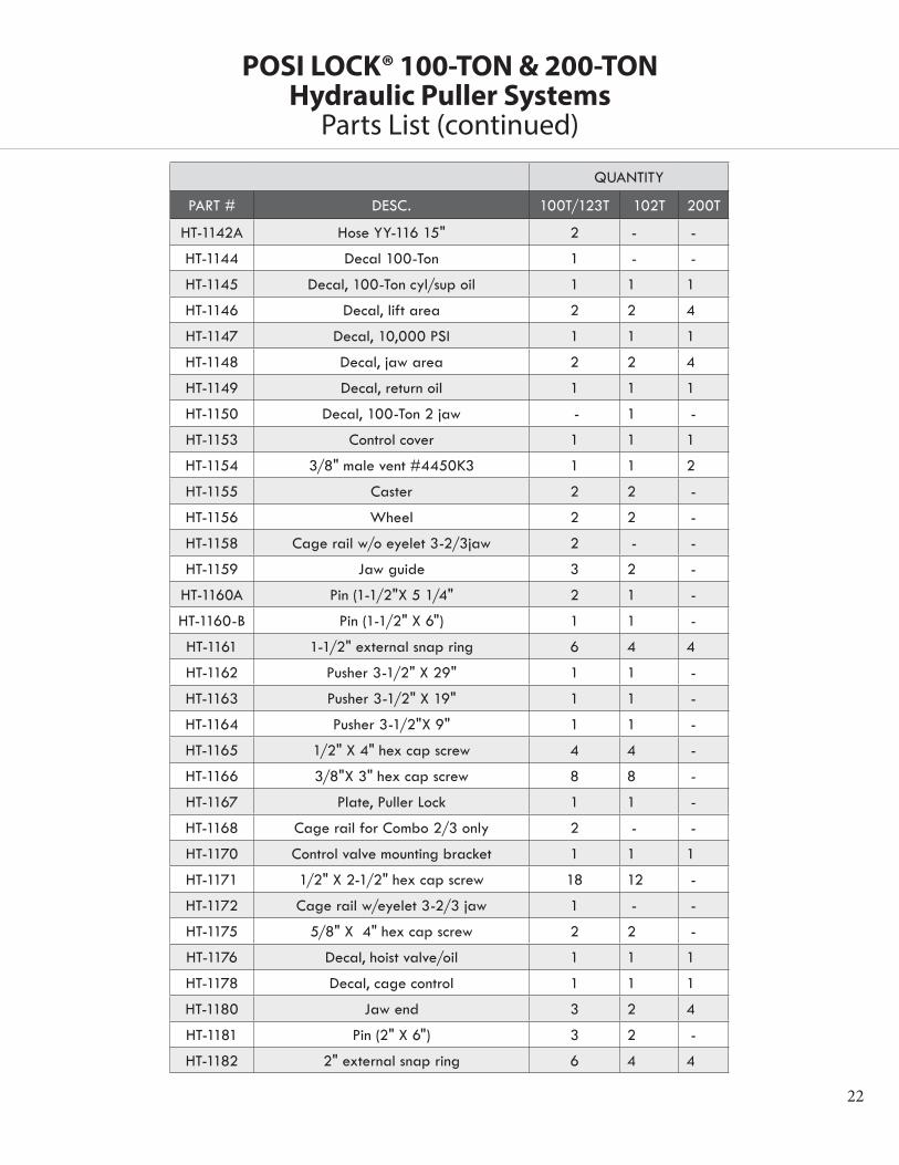
POSI LOCK® 100-TON & 200-TON Hydraulic Puller Systems
Parts List (continued)
QUANTITY
PART # DESC. 100T/123T 102T 200T
HT-1142A Hose YY-116 15" 2 - -
HT-1144 Decal 100-Ton 1 - -
HT-1145 Decal, 100-Ton cyl/sup oil 1 1 1
HT-1146 Decal, lift area 2 2 4
HT-1147 Decal, 10,000 PSI 1 1 1
HT-1148 Decal, jaw area 2 2 4
HT-1149 Decal, return oil 1 1 1
HT-1150 Decal, 100-Ton 2 jaw - 1 -
HT-1153 Control cover 1 1 1
HT-1154 3/8" male vent #4450K3 1 1 2
HT-1155 Caster 2 2 -
HT-1156 Wheel 2 2 -
HT-1158 Cage rail w/o eyelet 3-2/3jaw 2 - -
HT-1159 Jaw guide 3 2 -
HT-1160A Pin (1-1/2"X 5 1/4" 2 1 -
HT-1160-B Pin (1-1/2" X 6") 1 1 -
HT-1161 1-1/2" external snap ring 6 4 4
HT-1162 Pusher 3-1/2" X 29" 1 1 -
HT-1163 Pusher 3-1/2" X 19" 1 1 -
HT-1164 Pusher 3-1/2"X 9" 1 1 -
HT-1165 1/2" X 4" hex cap screw 4 4 -
HT-1166 3/8"X 3" hex cap screw 8 8 -
HT-1167 Plate, Puller Lock 1 1 -
HT-1168 Cage rail for Combo 2/3 only 2 - -
HT-1170 Control valve mounting bracket 1 1 1
HT-1171 1/2" X 2-1/2" hex cap screw 18 12 -
HT-1172 Cage rail w/eyelet 3-2/3 jaw 1 - -
HT-1175 5/8" X 4" hex cap screw 2 2 -
HT-1176 Decal, hoist valve/oil 1 1 1
HT-1178 Decal, cage control 1 1 1
HT-1180 Jaw end 3 2 4
HT-1181 Pin (2" X 6") 3 2 -
HT-1182 2" external snap ring 6 4 4

23
QUANTITY
PART # DESC. 100T/123T 102T 200T
HT-1187 Flow divider for 2 jaw - 1 2
HT-1190 10' return hose 1 1 1
HT-1191 Barbed male hose end - - 2
HT-1199 Adapter for pusher 1 1 -
HT-1205 Jaw head for 2 jaw - 1 -
HT-1206 Cage rail w/ eyelet (2 jaw) - 1 -
HT-1207 Cage rail w/o eyelet (2 jaw) - 1 -
HT-1208 Coupler for pusher 1 1 -
HT-20013 200 -Ton cylinder D/A - - 1
HT-2005A Hose AA4 - 34" with 3" elbow - - 1
HT-2005B Hose AA5 - 78" - - 1
HT-2159 200-Ton jaw guide - - 2
HT-2160A Pin 1 1/2 x 13 13/16 - - 2
HT-2162 200-Ton pusher 29" - - 1
HT-2163 200-Ton pusher 19" - - 1
HT-2164 200-Ton pusher 9" - - 1
HT-2181 Pin 2 x 12 3/16 - - 2
HT-2199 Adaptor for pushers - - 1
HT-2204 3-Ton cylinder spacer - - 2
HT-2204-1 3-Ton cylinder spacer - - 4
HT-2206 200-Ton upper cage - - 1
HT-2207 200-Ton lower cage - - 1
HT-2210 Jaw guide spacer - - 8
HT-2405 Jaw head for 200-Ton puller - - 1
HT-9306K34 Bumper stops - - 2
HT-2150 Decal, 200-Ton 4 jaw - - 1
HT-2171 1/2" x 3 1/4' hex head cap SCR - - 12
UW16 1" Dia. hardened washer - - 2
HT-1029 1" x 1 1/4" hex head cap SCR - - 2
HT-1030 1" lock washer - - 2
HT-2170DA Control valve nounting bracket - - 1
HT-2106B Pin 1 x 12 1/2" - - 2
POSI LOCK® 100-TON & 200-TON Hydraulic Puller Systems
Parts List (continued)

24
QUANTITY
PART # DESC. 100T/123T 102T 200T
HT-2111AR 200-Ton Mast - - 1
HT-2112 200-Ton Puller Slide - - 2
HT-ST1 Steel Tube 1 1 1
HT-ST2 Steel Tube 1 1 1
HT-ST3 Steel Tube 1 1 1
HT-ST4 Steel Tube - 1 1
HT-ST5 Steel Tube 1 1 -
HT-VC4 4-Way Valve 1 1 2
HT-CH604 Male Coupler - - 3
HT-VC20 4-Way Closed Center Valve 1 1 1
HT-V82 Needle Valve 1 1 1
HT-CR400 Female Coupler - - 3
PH-10010 100-Ton Cylinder 1 1 -
PH-2022 Electric Pump 1 1
PGB254TLM Gauge 1 1 1
HT-GA3 Gauge Adapter 1 1 1
PH-411 Dust Cap 3 3 -
PH-927 Hose 10' 1 - 1
FHCH-38M Male Coupler 3 3 -
FHCH-38F Female Coupler 3 3 -
200-Ton Hydraulic Pump - - 1
POSI LOCK® 100-TON & 200-TON Hydraulic Puller Systems
Parts List (continued)

25
POSI LOCK® 100-TON & 200-TON Hydraulic Puller Systems
WARRANTYAll POSI LOCK forged parts carry a lifetime warranty with the exception of transmission jaws. All other POSI LOCK parts and components are guaranteed for one year against defects in materials and workmanship to meet the exacting standards and requirements of professional maintenance. Every product manufactured by POSI LOCK and found to be defective (by the factory) in either material or workmanship, will be repaired or replaced. This warranty applies to the original purchaser (end user) only and is nontransferable.
This warranty does not cover any product or part that has been abused, worn out, heated, ground or otherwise altered, used for a purpose other than that for which it was intended or used in a manner inconsistent with any instructions regarding its use. Use of an impact wrench voids the warranty.
Damaged components, including bent rams, dented or crushed cylinder walls are the result of misuse, misapplication or a combination of both and will not be considered under warranty. Normal wear such as worn out seals, couplers, O-rings and springs does not constitute a defect and will not be considered for warranty credit. The foregoing constitutes the only warranty made by the company.
In the unlikely event that product fails due to material or workmanship defect, you are instructed to contact the POSI LOCK warranty division at +1- 701- 797-2600 or [email protected]. Except where such limitations and exclusions are specifically prohibited by law, the consumer’s sole and exclusive remedy shall be the repair or replacement of the defective product.
POSI LOCK shall not be liable for any consequential or incidental damage or loss whatsoever. Any and all expressed and implied warranties, including without limitation, any warranties of merchantability and fitness for a particular purpose, are limited to the original purchaser. Some states do not allow the exclusion or limitation of incidental or consequential damages, so the above may not apply to you. This warranty gives you specific legal rights. You may also have other rights which vary from state to state.
Hydraulic components not manufactured by POSI LOCK. Please refer to the original manufacturer’s warranty statement.
Notice: POSI LOCK reserves the right to make changes in design or construction of tools and equipment without obligation to incorporate such changes in tools and equipment previously sold.
Posi Lock Puller, Inc.805 Sunflower Avenue | PO Box 246 | Cooperstown, North Dakota | USA | 58425Phone: +1-701-797-2600 | Fax: [email protected] | www.posilock.com Rev. 2015