100 series hydraulic cylinders - golftechs.usgolftechs.us/manuals/jdhydcyl.pdf100 series hydraulic...
TRANSCRIPT

100 Series HydraulicCylinders
TECHNICAL MANUAL100 Series Hydraulic Cylinders
TM-H100A 30NOV01 (ENGLISH)
John Deere Harvester WorksLITHO IN U.S.A.

Introduction
CED,OUO1032,1193 –19–04JAN99–1/1
Foreword
This manual is written for an experienced technician.Essential tools required in performing certain servicework are identified in this manual and arerecommended for use.
Live with safety: Read the safety messages in theintroduction of this manual and the cautions presentedthroughout the text of the manual.
This is the safety-alert symbol. When you see thissymbol on the machine or in this manual, be alert tothe potential for personal injury.
See machine technical manual for procedure toremove and install cylinders.
Fundamental service information is available fromother sources covering basic theory of operation,fundamentals of troubleshooting, general maintenance,and basic types of failures and their causes.
Cylinder Technical Manuals are concise service guideswritten as stand-alone manuals, supporting a specificseries of hydraulic cylinders.
This Cylinder Technical Manual covers recommendedrepair procedures for the John Deere 100 SeriesHydraulic Cylinder.
(30NOV01) 100 Series Hydraulic Cylinders113001
PN=2

ContentsSECTION —100 Series Hydraulic Cylinders
Group 05—SafetyGroup 10—Hydraulic Cylinder DiagnosticsGroup 15—100 Wire Locked CylinderGroup 20—100 External Snap Ring
INDXGroup 25—100C External Snap Ring
All information, illustrations and specifications in this manual are based onthe latest information available at the time of publication. The right isreserved to make changes at any time without notice.
COPYRIGHT 2001DEERE & COMPANY
Moline, IllinoisAll rights reserved
A John Deere ILLUSTRUCTION Manual
TM-H100A (30NOV01) i 100 Series Hydraulic Cylinders113001
PN=1
Contents
INDX
TM-H100A (30NOV01) ii 100 Series Hydraulic Cylinders113001
PN=2

Section100 Series Hydraulic Cylinders
Contents
Page
Group 05—Safety . . . . . . . . . . . . . . . . . . . . . . . . 05-1
Group 10—Hydraulic Cylinder DiagnosticsHydraulic Cylinder Diagnostics . . . . . . . . . . . . . . . 10-1Hydraulic Cylinder Drift Diagnostics. . . . . . . . . . . . 10-1
Group 15—100 Wire Locked CylinderOther Material . . . . . . . . . . . . . . . . . . . . . . . . . . . . 15-1Disassemble and Assemble Cylinder . . . . . . . . . . 15-1
Group 20—100 External Snap RingOther Material . . . . . . . . . . . . . . . . . . . . . . . . . . . . 20-1Disassemble and Assemble Cylinder . . . . . . . . . . 20-1
Group 25—100C External Snap RingOther Material . . . . . . . . . . . . . . . . . . . . . . . . . . . . 25-1Disassemble and Assemble Cylinder . . . . . . . . . . 25-1
TM-H100A (30NOV01) 1 100 Series Hydraulic Cylinders113001
PN=1
Contents
TM-H100A (30NOV01) 2 100 Series Hydraulic Cylinders113001
PN=2

Group 05Safety
051
DX,FLAME –19–29SEP98–1/1
Handle Fluids Safely—Avoid Fires
TS
227
–UN
–23A
UG
88
When you work around fuel, do not smoke or work nearheaters or other fire hazards.
Store flammable fluids away from fire hazards. Do notincinerate or puncture pressurized containers.
Make sure machine is clean of trash, grease, and debris.
Do not store oily rags; they can ignite and burnspontaneously.
DX,FIRE2 –19–03MAR93–1/1
Prepare for Emergencies
TS
291
–UN
–23A
UG
88
Be prepared if a fire starts.
Keep a first aid kit and fire extinguisher handy.
Keep emergency numbers for doctors, ambulance service,hospital, and fire department near your telephone.
(30NOV01) 05-1 100 Series Hydraulic Cylinders113001
PN=7

Safety
052
DX,FLUID –19–03MAR93–1/1
Avoid High-Pressure Fluids
X98
11–U
N–2
3AU
G88
Escaping fluid under pressure can penetrate the skincausing serious injury.
Avoid the hazard by relieving pressure beforedisconnecting hydraulic or other lines. Tighten allconnections before applying pressure.
Search for leaks with a piece of cardboard. Protect handsand body from high pressure fluids.
If an accident occurs, see a doctor immediately. Any fluidinjected into the skin must be surgically removed within afew hours or gangrene may result. Doctors unfamiliar withthis type of injury should reference a knowledgeablemedical source. Such information is available from Deere& Company Medical Department in Moline, Illinois, U.S.A.
DX,LOWER –19–24FEB00–1/1
Support Machine Properly
TS
229
–UN
–23A
UG
88
Always lower the attachment or implement to the groundbefore you work on the machine. If the work requires thatthe machine or attachment be lifted, provide securesupport for them. If left in a raised position, hydraulicallysupported devices can settle or leak down.
Do not support the machine on cinder blocks, hollow tiles,or props that may crumble under continuous load. Do notwork under a machine that is supported solely by a jack.Follow recommended procedures in this manual.
When implements or attachments are used with amachine, always follow safety precautions listed in theimplement or attachment operator’s manual.
(30NOV01) 05-2 100 Series Hydraulic Cylinders113001
PN=8

Safety
053
DX,WEAR2 –19–03MAR93–1/1
Wear Protective Clothing
TS
206
–UN
–23A
UG
88
Wear close fitting clothing and safety equipmentappropriate to the job.
Operating equipment safely requires the full attention ofthe operator. Do not wear radio or music headphoneswhile operating machine.
DX,LOOSE –19–04JUN90–1/1
Service Machines Safely
TS
228
–UN
–23A
UG
88
Tie long hair behind your head. Do not wear a necktie,scarf, loose clothing, or necklace when you work nearmachine tools or moving parts. If these items were to getcaught, severe injury could result.
Remove rings and other jewelry to prevent electricalshorts and entanglement in moving parts.
DX,LIGHT –19–04JUN90–1/1
Illuminate Work Area Safely
TS
223
–UN
–23A
UG
88
Illuminate your work area adequately but safely. Use aportable safety light for working inside or under themachine. Make sure the bulb is enclosed by a wire cage.The hot filament of an accidentally broken bulb can ignitespilled fuel or oil.
DX,LIFT –19–04JUN90–1/1
Use Proper Lifting Equipment
TS
226
–UN
–23A
UG
88
Lifting heavy components incorrectly can cause severeinjury or machine damage.
Follow recommended procedure for removal andinstallation of components in the manual.
(30NOV01) 05-3 100 Series Hydraulic Cylinders113001
PN=9

Safety
054
DX,CLEAN –19–04JUN90–1/1
Work In Clean Area
T66
42E
J–U
N–1
8OC
T88
Before starting a job:
• Clean work area and machine.• Make sure you have all necessary tools to do your job.• Have the right parts on hand.• Read all instructions thoroughly; do not attempt
shortcuts.
DX,REPAIR –19–17FEB99–1/1
Use Proper Tools
TS
779
–UN
–08N
OV
89
Use tools appropriate to the work. Makeshift tools andprocedures can create safety hazards.
Use power tools only to loosen threaded parts andfasteners.
For loosening and tightening hardware, use the correctsize tools. DO NOT use U.S. measurement tools onmetric fasteners. Avoid bodily injury caused by slippingwrenches.
Use only service parts meeting John Deere specifications.
(30NOV01) 05-4 100 Series Hydraulic Cylinders113001
PN=10

Safety
055
DX,DRAIN –19–03MAR93–1/1
Dispose of Waste Properly
TS
1133
–UN
–26N
OV
90
Improperly disposing of waste can threaten theenvironment and ecology. Potentially harmful waste usedwith John Deere equipment include such items as oil, fuel,coolant, brake fluid, filters, and batteries.
Use leakproof containers when draining fluids. Do not usefood or beverage containers that may mislead someoneinto drinking from them.
Do not pour waste onto the ground, down a drain, or intoany water source.
Air conditioning refrigerants escaping into the air candamage the Earth’s atmosphere. Government regulationsmay require a certified air conditioning service center torecover and recycle used air conditioning refrigerants.
Inquire on the proper way to recycle or dispose of wastefrom your local environmental or recycling center, or fromyour John Deere dealer.
DX,LIVE –19–25SEP92–1/1
Live With Safety
TS
231
–19–
07O
CT
88
Before returning machine to customer, make suremachine is functioning properly, especially the safetysystems. Install all guards and shields.
(30NOV01) 05-5 100 Series Hydraulic Cylinders113001
PN=11

Safety
056
(30NOV01) 05-6 100 Series Hydraulic Cylinders113001
PN=12

Group 10Hydraulic Cylinder Diagnostics
101
AG,HX00517,18 –19–06AUG99–1/1
Hydraulic Cylinder Diagnostics
– – –1/1
Hydraulic Cylinder Drift Diagnostics
– – –1/1
1 Cylinder Identification Is the cylinder you are working with a rephasing cylinder? YES: GO TO 4
NO: GO TO 2
– – –1/1
2 Preparing Cylinderfor Testing
Relieve all pressure from the cylinder by either putting the valve, that controls thecylinder, into the float position or by turning off the machine’s engine and moving thevalve controlling the cylinder(s) from extend to retract positions.
NOTE: If machine has pilot operated or electro-hydraulic valves see machine manualfor instructions on how to relieve all pressure from the cylinder.
Disconnect the cylinder from the machine by removing the pin at the ROD END.
RETRACT the cylinder fully and shut off the machine.
NOTE: To check individual cylinders, disconnect the hoses or lines from the cylindernot being tested and cap off the fittings on the lines for those cylinders to allow you toisolate the cylinder you are testing.
YES: GO TO 3
(30NOV01) 10-1 100 Series Hydraulic Cylinders113001
PN=13

Hydraulic Cylinder Diagnostics
102
– – –1/1
3 Testing Cylinder forLeaks
Disconnect the PISTON END line from the machine, and remove coupler if necessary,and place the line in a pail or pan.
Cap line remaining on machine.
Start the machine and move the valve slowly in the direction to retract the cylinder.
Does oil continue to escape out of the return line as you hold the valve in the retractposition?
Note: A small amount of oil may escape from the fitting or line do to oil being trappedin the line when it was disconnected.
HCD1095 –UN–28NOV01
A—PressureB—PailC—Cap
YES: Cylinder is leakingaround the piston seal orthe cylinder bore isscored.
Repair or ReplaceCylinder.
GO TO 1
NO: Cylinder is good.
Test the other cylinders inthis system with thissame procedure.
GO TO 1
OR refer to machinemanual to test the valve.
– – –1/1
4 Rephasing CylinderIdentification
Does this rephasing cylinder rephase in the RETRACT position? YES: GO TO 5
NO: GO TO 2
(30NOV01) 10-2 100 Series Hydraulic Cylinders113001
PN=14

Hydraulic Cylinder Diagnostics
103
– – –1/1
5 Preparing Cylinderfor Testing
Relieve all pressure off of the cylinder by either putting the valve, that controls thecylinder, into the float position or by turning off the machine’s engine and moving thevalve controlling the cylinder(s) from extend to retract positions.
Disconnect the cylinder from the machine by removing the pin at the ROD END.
CAUTION: Make sure you have room on the machine to fully extend thecylinder with out the rod contacting anything. If there is insufficient roomremove the cylinder completely from the machine.
EXTEND the cylinder fully and shut off the machine.
CAUTION: If the piston nut is missing off of the rod, the rod could bepropelled out of the cylinder.
NOTE: To check individual cylinders, disconnect the hoses or lines from the cylindernot being tested and cap off the fittings on the lines for those cylinders to allow you toisolate the cylinder you are testing.
YES: GO TO 6
– – –1/1
6 Testing Cylinder forLeaks
Disconnect the ROD END line from the machine, and remove coupler if necessary,and place the line in a pail or pan.
Cap line remaining on machine.
Start the machine and slowly move the valve in the direction to extend the cylinder.
CAUTION: If the piston nut is missing off of the rod, the rod could bepropelled out of the cylinder.
Does oil continue to escape out of the ROD END as you hold the valve in the extendposition?
NOTE: A small amount of oil may escape from the fitting or line do to oil being trappedin the line when it was disconnected.
HCD1094 –UN–28NOV01
A—PressureB—PailC—Cap
YES: Cylinder is leakingaround the piston seal orthe cylinder bore isscored.
Repair or ReplaceCylinder.
GO TO 1
NO: Cylinder is good.
Test the other cylinders inthis system with thissame procedure or referto machine manual to testthe valve.
GO TO 1
(30NOV01) 10-3 100 Series Hydraulic Cylinders113001
PN=15

Hydraulic Cylinder Diagnostics
104
(30NOV01) 10-4 100 Series Hydraulic Cylinders113001
PN=16

Group 15100 Wire Locked Cylinder
151
OUO6046,00016B1 –19–08NOV01–1/1
Other Material
Number Name Use
T43512 (U.S.) Thread Lock and Sealer (Medium Used to lock threads duringTY9473 (Canadian) Strength) assembly242 (LOCTITE)
LOCTITE is a trademark of Loctite Corp.
OUO6046,00016AC –19–05NOV01–1/10
Disassemble and Assemble Cylinder
HC
D11
03–U
N–2
8NO
V01
A—Lock RingB—Rod Guide
IMPORTANT: Clamping cylinder in a vise at themiddle or rod end of barrel may damagethe barrel. Clamp only at the cylinderbase end.
Extend rod to remove oil or air betweenrod piston and rod guide. Excessiveamounts of trapped oil or air willexpand seals and make disassemblymore difficult.
1. Open both ports and drain all oil from the cylinder.
2. Extend rod fully.
3. Clean outside surface of cylinder with suitable solventand dry to prevent dirt and debris from enteringcylinder barrel.
4. Lift lock ring (A) out of slot using screwdriver.
NOTE: Spraying penetrating oil in access slot may easein disassembly.
5. Rotate end of rod guide (B) in same direction end oflock ring is pointing, to rotate lock ring out of slot, whilepulling on lock ring.
Continued on next page
(30NOV01) 15-1 100 Series Hydraulic Cylinders113001
PN=17
100 Wire Locked Cylinder
152
OUO6046,00016AC –19–05NOV01–2/10
HC
D10
93–U
N–1
9NO
V01
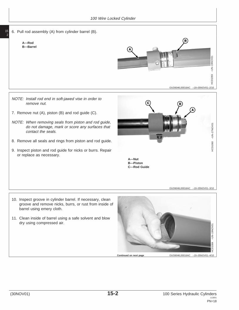
A—RodB—Barrel
6. Pull rod assembly (A) from cylinder barrel (B).
OUO6046,00016AC –19–05NOV01–3/10
HC
D10
60–U
N–2
7NO
V01
A—NutB—PistonC—Rod Guide
NOTE: Install rod end in soft-jawed vise in order toremove nut.
7. Remove nut (A), piston (B) and rod guide (C).
NOTE: When removing seals from piston and rod guide,do not damage, mark or score any surfaces thatcontact the seals.
8. Remove all seals and rings from piston and rod guide.
9. Inspect piston and rod guide for nicks or burrs. Repairor replace as necessary.
OUO6046,00016AC –19–05NOV01–4/10
HC
D10
84–U
N–1
9NO
V01
10. Inspect groove in cylinder barrel. If necessary, cleangroove and remove nicks, burrs, or rust from inside ofbarrel using emery cloth.
11. Clean inside of barrel using a safe solvent and blowdry using compressed air.
Continued on next page
(30NOV01) 15-2 100 Series Hydraulic Cylinders113001
PN=18
100 Wire Locked Cylinder
153
OUO6046,00016AC –19–05NOV01–5/10
HC
D10
96–U
N–2
7NO
V01
HC
D10
99–U
N–2
6NO
V01
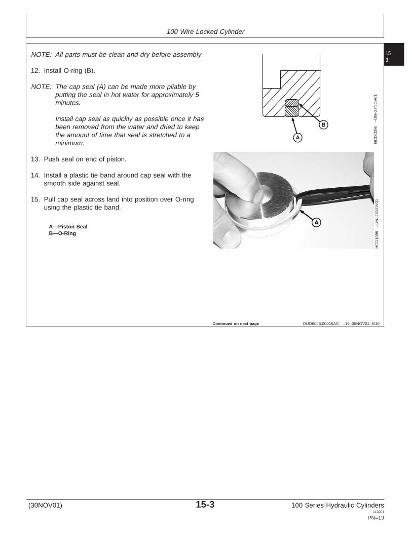
A—Piston SealB—O-Ring
NOTE: All parts must be clean and dry before assembly.
12. Install O-ring (B).
NOTE: The cap seal (A) can be made more pliable byputting the seal in hot water for approximately 5minutes.
Install cap seal as quickly as possible once it hasbeen removed from the water and dried to keepthe amount of time that seal is stretched to aminimum.
13. Push seal on end of piston.
14. Install a plastic tie band around cap seal with thesmooth side against seal.
15. Pull cap seal across land into position over O-ringusing the plastic tie band.
Continued on next page
(30NOV01) 15-3 100 Series Hydraulic Cylinders113001
PN=19

100 Wire Locked Cylinder
154
OUO6046,00016AC –19–05NOV01–6/10
HC
D10
98–U
N–3
0NO
V01
A—Shim StockB—Hose Clamp
16. Check if cap seal is loose; seal must fit tight and notturn. If seal can be turned, it has been stretched toomuch and can be damaged during assembly intobarrel.
17. If necessary, shrink cap seal to its original size usinga ring compressor or a hose clamp (B).
Protect by placing shim stock or protective materialbetween seal and clamp when compressing.
Seal will also shrink to its original size if left for aminimum of 8 hours before installing assembly intobarrel.
Continued on next page
(30NOV01) 15-4 100 Series Hydraulic Cylinders113001
PN=20
100 Wire Locked Cylinder
155
OUO6046,00016AC –19–05NOV01–7/10
HC
D10
63–U
N–2
8NO
V01
HC
D10
80–U
N–1
3NO
V01
HC
D10
81–U
N–1
9NO
V01
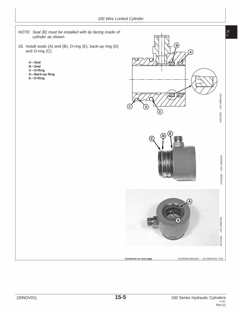
A—SealB—SealC—O-RingD—Back-up RingE—O-Ring
NOTE: Seal (B) must be installed with lip facing inside ofcylinder as shown.
18. Install seals (A) and (B), O-ring (E), back-up ring (D)and O-ring (C).
Continued on next page
(30NOV01) 15-5 100 Series Hydraulic Cylinders113001
PN=21
100 Wire Locked Cylinder
156
OUO6046,00016AC –19–05NOV01–8/10
HC
D11
04–U
N–2
8NO
V01
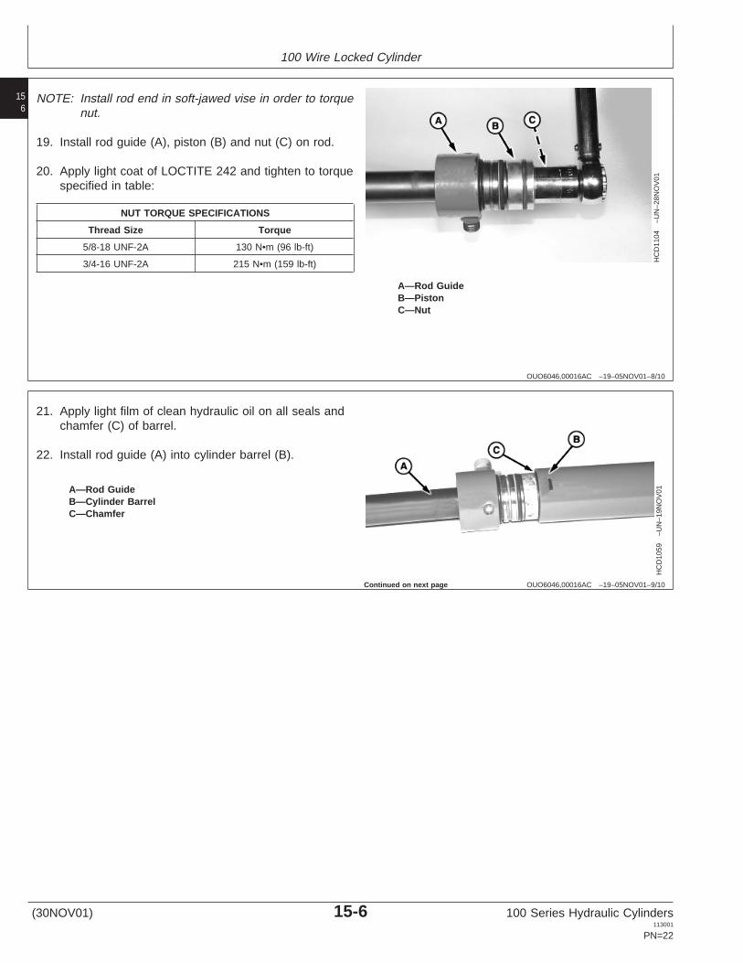
A—Rod GuideB—PistonC—Nut
NOTE: Install rod end in soft-jawed vise in order to torquenut.
19. Install rod guide (A), piston (B) and nut (C) on rod.
20. Apply light coat of LOCTITE 242 and tighten to torquespecified in table:
NUT TORQUE SPECIFICATIONS
Thread Size Torque
5/8-18 UNF-2A 130 N•m (96 lb-ft)
3/4-16 UNF-2A 215 N•m (159 lb-ft)
OUO6046,00016AC –19–05NOV01–9/10
HC
D10
59–U
N–1
9NO
V01A—Rod Guide
B—Cylinder BarrelC—Chamfer
21. Apply light film of clean hydraulic oil on all seals andchamfer (C) of barrel.
22. Install rod guide (A) into cylinder barrel (B).
Continued on next page
(30NOV01) 15-6 100 Series Hydraulic Cylinders113001
PN=22
100 Wire Locked Cylinder
157
OUO6046,00016AC –19–05NOV01–10/10
HC
D10
78–U
N–2
9NO
V01
HC
D11
05–U
N–2
8NO
V01
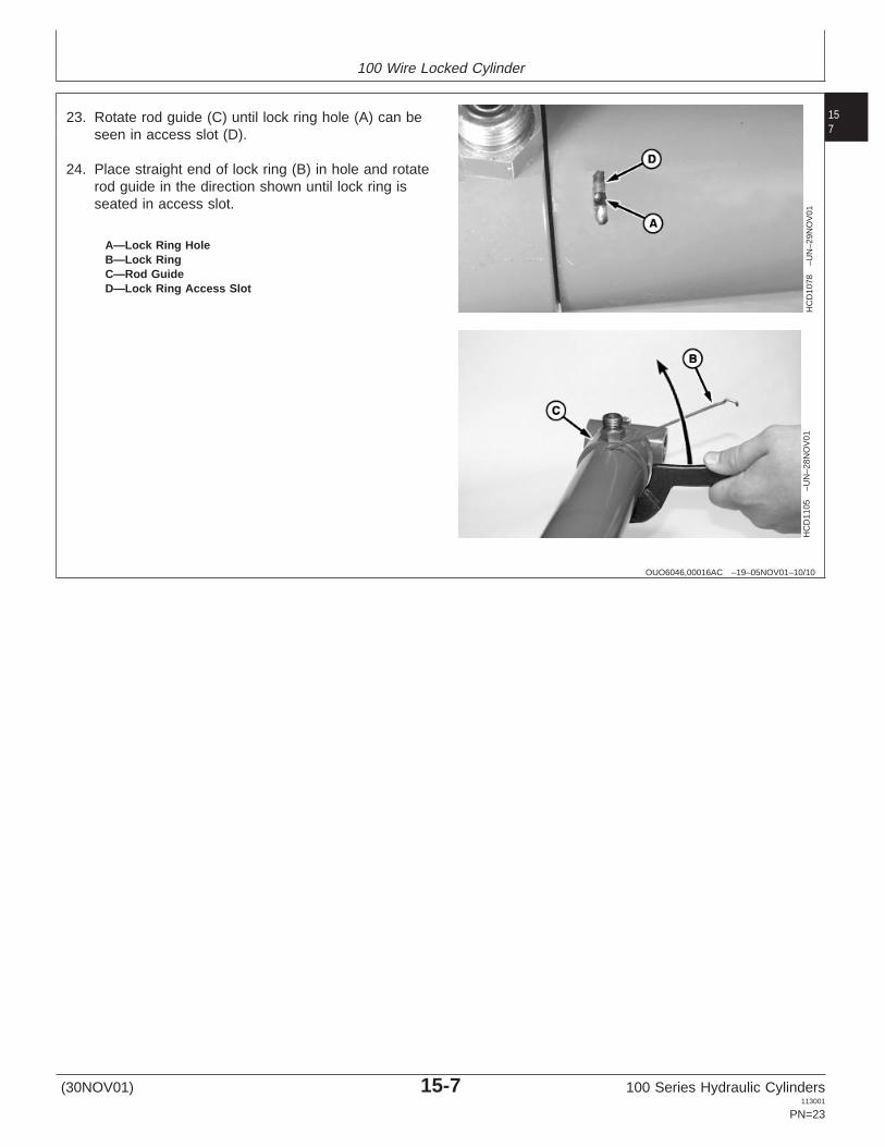
A—Lock Ring HoleB—Lock RingC—Rod GuideD—Lock Ring Access Slot
23. Rotate rod guide (C) until lock ring hole (A) can beseen in access slot (D).
24. Place straight end of lock ring (B) in hole and rotaterod guide in the direction shown until lock ring isseated in access slot.
(30NOV01) 15-7 100 Series Hydraulic Cylinders113001
PN=23

100 Wire Locked Cylinder
158
(30NOV01) 15-8 100 Series Hydraulic Cylinders113001
PN=24

Group 20100 External Snap Ring
201
OUO6046,00016B1 –19–08NOV01–1/1
Other Material
Number Name Use
T43512 (U.S.) Thread Lock and Sealer (Medium Used to lock threads duringTY9473 (Canadian) Strength) assembly242 LOCTITE (LOCTITE)
OUO6046,00016B0 –19–07NOV01–1/12
Disassemble and Assemble Cylinder
HC
D10
56–U
N–0
8NO
V01
A—Snap Ring
IMPORTANT: Clamping cylinder in a vise at themiddle or rod end of barrel may damagethe barrel. Clamp only at the cylinderbase end.
Extend rod to remove oil or air betweenrod piston and rod guide. Excessiveamounts of trapped oil or air willexpand seals and make disassemblymore difficult.
1. Open both ports and drain all oil from the cylinder.
2. Extend rod fully.
3. Clean outside surface of cylinder with suitable solventand dry to prevent dirt and debris from enteringcylinder barrel.
4. Remove external snap ring (A) using snap ring pliers.
Continued on next page
(30NOV01) 20-1 100 Series Hydraulic Cylinders113001
PN=25

100 External Snap Ring
202
OUO6046,00016B0 –19–07NOV01–2/12
HC
D10
66–U
N–1
3NO
V01
HC
D10
67–U
N–1
3NO
V01
HC
D10
97–U
N–2
8NO
V01
A—Rod GuideB—Filler Ring
5. Using a wooden dowel or brass drift, drive rod guide(A) into cylinder past barrel snap ring groove.
6. Remove any debris in barrel snap ring groove.
IMPORTANT: If filler ring (B) is installed backwards,snap ring may not disengage and fillerring could be damaged.
7. Install filler ring (B), supplied with cylinder seal kit, intobarrel snap ring groove in the direction shown toprevent snap ring from engaging in barrel snap ringgroove during removal.
Continued on next page
(30NOV01) 20-2 100 Series Hydraulic Cylinders113001
PN=26

100 External Snap Ring
203
OUO6046,00016B0 –19–07NOV01–3/12
HC
D10
68–U
N–0
8NO
V01
A—Snap RingB—Rod AssemblyC—NutD—PistonE—Rod Guide
8. Pull rod assembly (B) with snap ring (A) from cylinderbarrel.
NOTE: Install rod end in soft-jawed vise in order toremove nut.
9. Remove nut (C), piston (D) and rod guide (E).
10. Remove groove filler ring from snap ring groove. Donot use for reassembly.
NOTE: When removing seals from piston and rod guide,do not damage, mark or score any surfaces thatcontact the seals.
11. Remove all seals and rings on piston and rod guide.
12. Inspect piston, barrel and rod guide for nicks or burrs.Repair or replace as necessary.
OUO6046,00016B0 –19–07NOV01–4/12H
CD
1061
–UN
–19N
OV
01
13. Inspect groove in cylinder barrel. If necessary, cleangroove and remove nicks, burrs, or rust from inside ofbarrel using emery cloth.
14. Clean inside of barrel using a safe solvent and blowdry using compressed air.
Continued on next page
(30NOV01) 20-3 100 Series Hydraulic Cylinders113001
PN=27
100 External Snap Ring
204
OUO6046,00016B0 –19–07NOV01–5/12
HC
D11
02–U
N–2
8NO
V01
HC
D11
01–U
N–2
7NO
V01
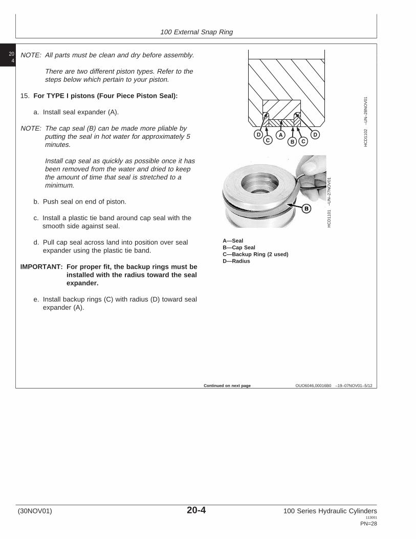
A—SealB—Cap SealC—Backup Ring (2 used)D—Radius
NOTE: All parts must be clean and dry before assembly.
There are two different piston types. Refer to thesteps below which pertain to your piston.
15. For TYPE I pistons (Four Piece Piston Seal):
a. Install seal expander (A).
NOTE: The cap seal (B) can be made more pliable byputting the seal in hot water for approximately 5minutes.
Install cap seal as quickly as possible once it hasbeen removed from the water and dried to keepthe amount of time that seal is stretched to aminimum.
b. Push seal on end of piston.
c. Install a plastic tie band around cap seal with thesmooth side against seal.
d. Pull cap seal across land into position over sealexpander using the plastic tie band.
IMPORTANT: For proper fit, the backup rings must beinstalled with the radius toward the sealexpander.
e. Install backup rings (C) with radius (D) toward sealexpander (A).
Continued on next page
(30NOV01) 20-4 100 Series Hydraulic Cylinders113001
PN=28

100 External Snap Ring
205
OUO6046,00016B0 –19–07NOV01–6/12
HC
D10
69–U
N–2
8NO
V01
HC
D10
99–U
N–2
6NO
V01
A—Cap SealB—O-Ring
16. For TYPE II pistons (Two Piece Piston Seal):
a. Install O-ring (B).
NOTE: The cap seal (A) can be made more pliable byputting the seal in hot water for approximately 5minutes.
Install cap seal as quickly as possible once it hasbeen removed from the water and dried to keepthe amount of time that seal is stretched to aminimum.
b. Push seal (A) on end of piston.
c. Install a plastic tie band around cap seal with thesmooth side against seal.
d. Pull cap seal across land into position over O-ringusing the plastic tie band.
Continued on next page
(30NOV01) 20-5 100 Series Hydraulic Cylinders113001
PN=29
100 External Snap Ring
206
OUO6046,00016B0 –19–07NOV01–7/12
HC
D10
98–U
N–3
0NO
V01
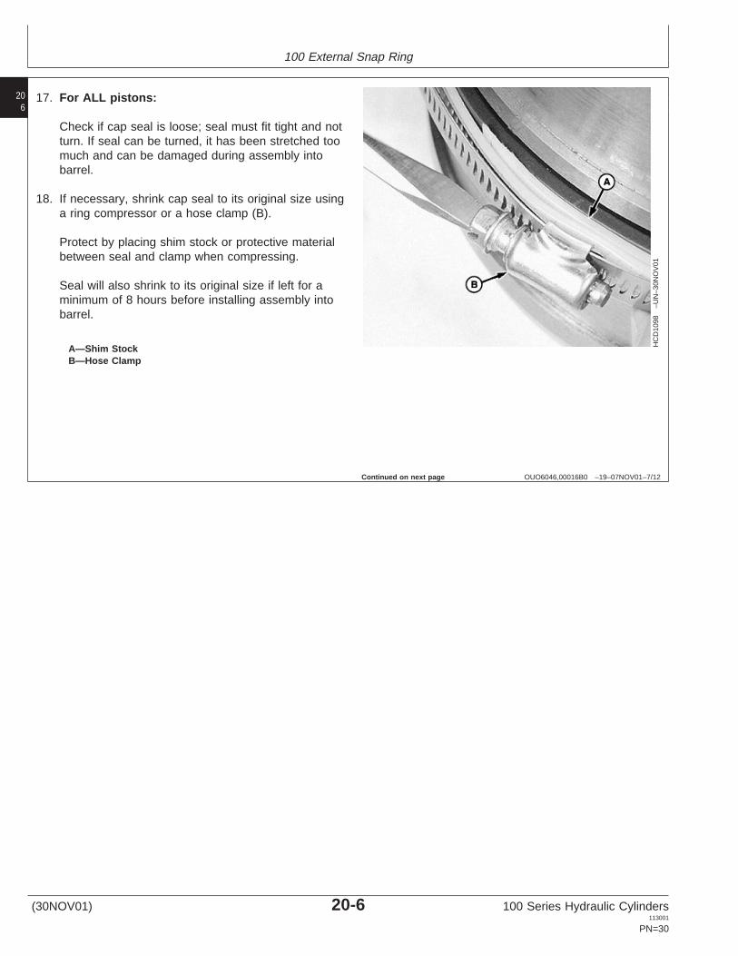
A—Shim StockB—Hose Clamp
17. For ALL pistons:
Check if cap seal is loose; seal must fit tight and notturn. If seal can be turned, it has been stretched toomuch and can be damaged during assembly intobarrel.
18. If necessary, shrink cap seal to its original size usinga ring compressor or a hose clamp (B).
Protect by placing shim stock or protective materialbetween seal and clamp when compressing.
Seal will also shrink to its original size if left for aminimum of 8 hours before installing assembly intobarrel.
Continued on next page
(30NOV01) 20-6 100 Series Hydraulic Cylinders113001
PN=30
100 External Snap Ring
207
OUO6046,00016B0 –19–07NOV01–8/12
HC
D10
70–U
N–2
7NO
V01
HC
D10
89–U
N–1
3NO
V01
HC
D10
90–U
N–1
3NO
V01
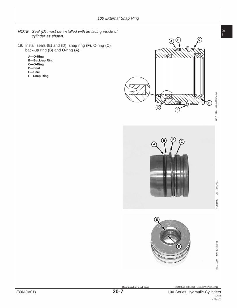
A—O-RingB—Back-up RingC—O-RingD—SealE—SealF—Snap Ring
NOTE: Seal (D) must be installed with lip facing inside ofcylinder as shown.
19. Install seals (E) and (D), snap ring (F), O-ring (C),back-up ring (B) and O-ring (A).
(30NOV01) 20-7 100 Series Hydraulic Cylinders113001
PN=31
Continued on next page

100 External Snap Ring
208
OUO6046,00016B0 –19–07NOV01–9/12
HC
D11
06–U
N–2
8NO
V01
A—External Snap RingB—Rod GuideC—PistonD—Nut
NOTE: Install rod end in soft-jawed vise in order to torquenut.
20. Install external snap ring (A), rod guide (B), piston (C)and nut (D) on rod.
21. Apply light coat of LOCTITE 242 and tighten to torquespecified in table. If torque turn is specified in table goto steps 22—24.
NUT TORQUE SPECIFICATIONS
Thread Size Torque
5/8-18 UNF-2A 130 N•m (96 lb-ft)
3/4-16 UNF-2A 215 N•m (159 lb-ft)
M12 x 1.5 100 N•m (74 lb-ft)
NUT TORQUE SPECIFICATION
Thread Size Torque Turn
M16 x 1.5 50 N•m (37 lb-ft) + 45°
OUO6046,00016B0 –19–07NOV01–10/12
T61
49A
G–U
N–1
9OC
T88
HC
D10
86–U
N–1
3NO
V01
A—WireB—Rod GuideC—Piston
22. Put tape around a socket. Make marks on the tape todivide the socket into 1/12’s. The marks will be 30°apart. These will serve as a handy visual referencefor determining “Degrees Beyond Snug Torque”.
23. Tape a piece of wire (A) on rod guide (B), over piston(C), pointing to one of the marks on the socket.
24. Turn piston nut beyond the snug torque, the numberof degrees specified in the table above.
(30NOV01) 20-8 100 Series Hydraulic Cylinders113001
PN=32
Continued on next page

100 External Snap Ring
209
OUO6046,00016B0 –19–07NOV01–11/12
HC
D10
71–U
N–1
9NO
V01
A—ChamferB—Hose clampC—Rod Guide
25. Apply light film of clean hydraulic oil on seals andchamfer (A) of barrel.
26. Compress the internal snap ring using a hose clamp(B) until snap ring is seated in groove on rod guideand then loosen a little.
NOTE: Remove hose clamp once internal snap ring hasentered cylinder bore to prevent damage toexternal O-ring.
27. Drive rod guide (C) into barrel until snap ring seats inthe barrel groove.
28. Pull forward on rod to ensure that it has locked.
OUO6046,00016B0 –19–07NOV01–12/12
HC
D10
56–U
N–0
8NO
V01
A—Snap Ring
29. Install snap ring (A).
(30NOV01) 20-9 100 Series Hydraulic Cylinders113001
PN=33

100 External Snap Ring
2010
(30NOV01) 20-10 100 Series Hydraulic Cylinders113001
PN=34
Group 25100C External Snap Ring
251
OUO6046,00016B1 –19–08NOV01–1/1
Other Material
Number Name Use
T43512 (U.S.) Thread Lock and Sealer (Medium Used to lock threads duringTY9473 (Canadian) Strength) assembly242 LOCTITE (LOCTITE)
OUO6046,00016AF –19–07NOV01–1/10
Disassemble and Assemble Cylinder
HC
D10
72–U
N–2
8NO
V01
A—Snap RingB—Rod Guide
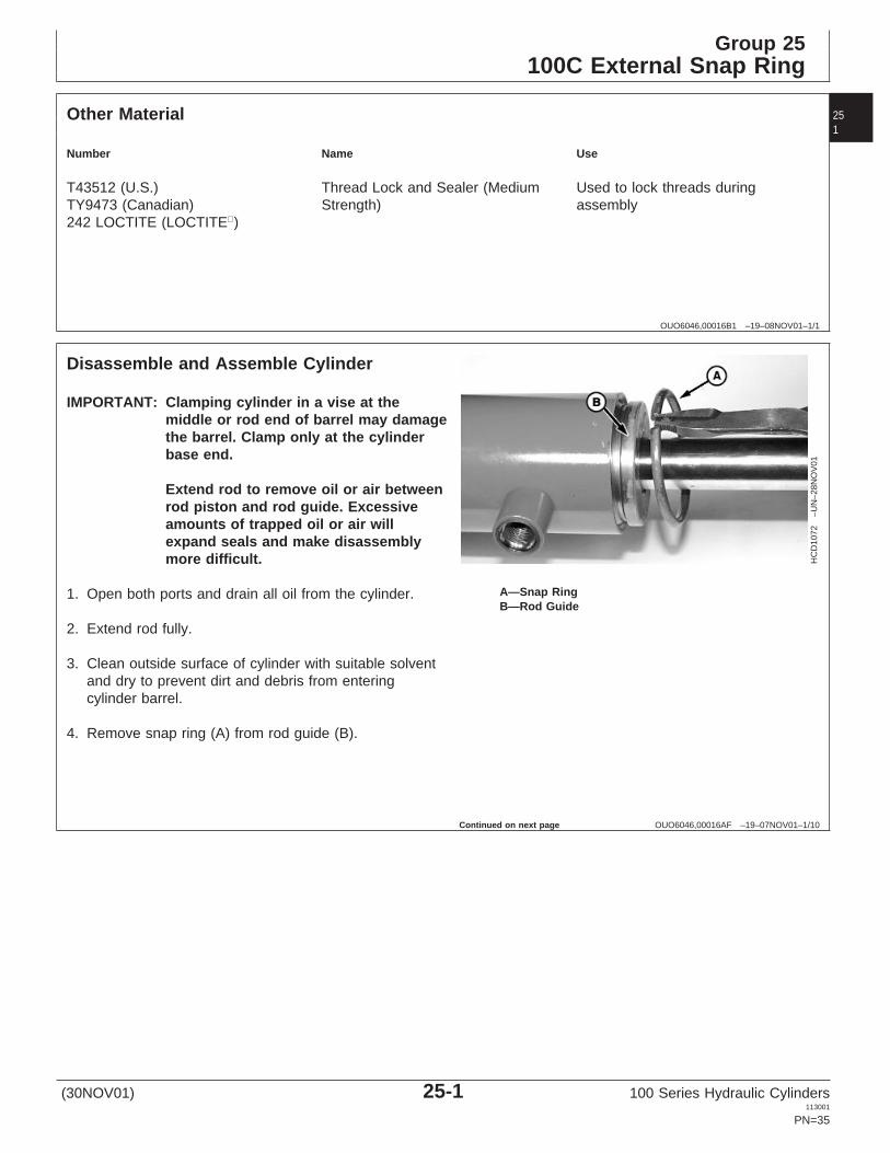
IMPORTANT: Clamping cylinder in a vise at themiddle or rod end of barrel may damagethe barrel. Clamp only at the cylinderbase end.
Extend rod to remove oil or air betweenrod piston and rod guide. Excessiveamounts of trapped oil or air willexpand seals and make disassemblymore difficult.
1. Open both ports and drain all oil from the cylinder.
2. Extend rod fully.
3. Clean outside surface of cylinder with suitable solventand dry to prevent dirt and debris from enteringcylinder barrel.
4. Remove snap ring (A) from rod guide (B).
Continued on next page
(30NOV01) 25-1 100 Series Hydraulic Cylinders113001
PN=35
100C External Snap Ring
252
OUO6046,00016AF –19–07NOV01–2/10
HC
D10
73–U
N–1
3NO
V01
HC
D10
75–U
N–2
9NO
V01
HC
D10
97–U
N–2
8NO
V01
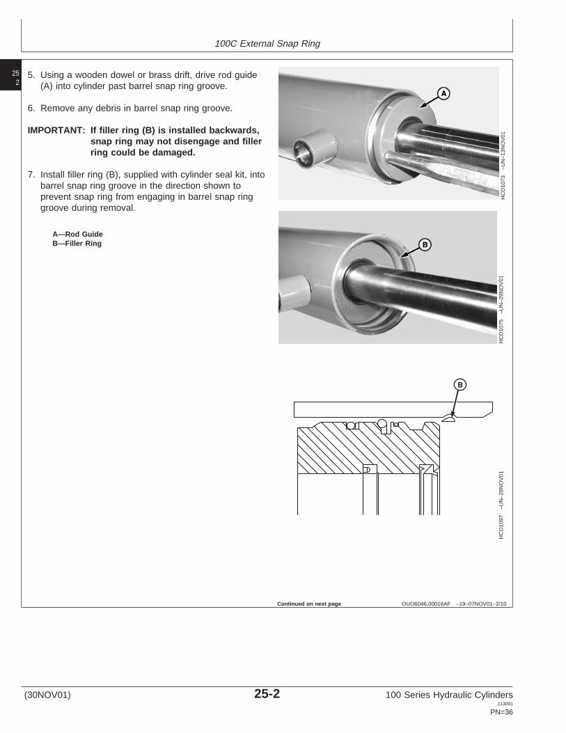
A—Rod GuideB—Filler Ring
5. Using a wooden dowel or brass drift, drive rod guide(A) into cylinder past barrel snap ring groove.
6. Remove any debris in barrel snap ring groove.
IMPORTANT: If filler ring (B) is installed backwards,snap ring may not disengage and fillerring could be damaged.
7. Install filler ring (B), supplied with cylinder seal kit, intobarrel snap ring groove in the direction shown toprevent snap ring from engaging in barrel snap ringgroove during removal.
Continued on next page
(30NOV01) 25-2 100 Series Hydraulic Cylinders113001
PN=36
100C External Snap Ring
253
OUO6046,00016AF –19–07NOV01–3/10
HC
D10
76–U
N–0
8NO
V01
HC
D10
77–U
N–0
8NO
V01
A—Rod AssemblyB—Cylinder BarrelC—NutD—PistonE—Rod Guide
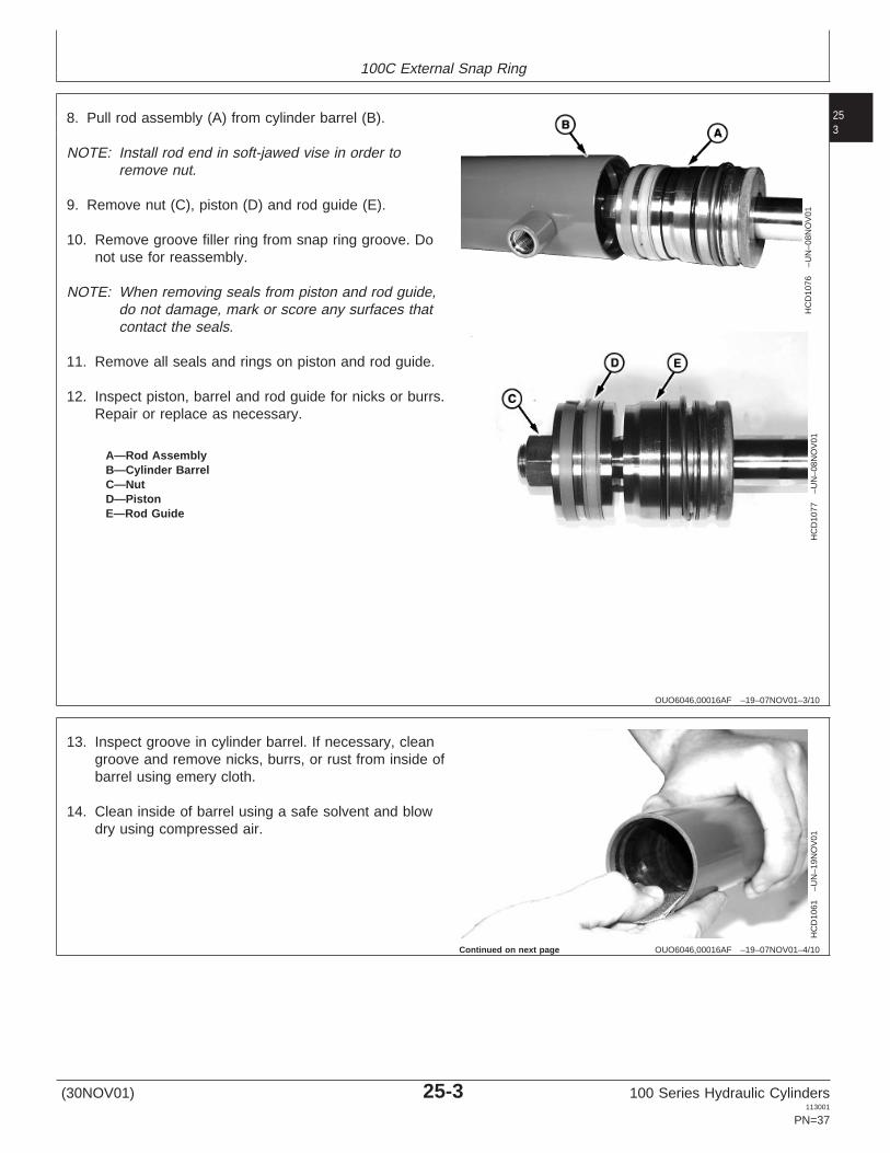
8. Pull rod assembly (A) from cylinder barrel (B).
NOTE: Install rod end in soft-jawed vise in order toremove nut.
9. Remove nut (C), piston (D) and rod guide (E).
10. Remove groove filler ring from snap ring groove. Donot use for reassembly.
NOTE: When removing seals from piston and rod guide,do not damage, mark or score any surfaces thatcontact the seals.
11. Remove all seals and rings on piston and rod guide.
12. Inspect piston, barrel and rod guide for nicks or burrs.Repair or replace as necessary.
OUO6046,00016AF –19–07NOV01–4/10
HC
D10
61–U
N–1
9NO
V01
13. Inspect groove in cylinder barrel. If necessary, cleangroove and remove nicks, burrs, or rust from inside ofbarrel using emery cloth.
14. Clean inside of barrel using a safe solvent and blowdry using compressed air.
Continued on next page
(30NOV01) 25-3 100 Series Hydraulic Cylinders113001
PN=37

100C External Snap Ring
254
OUO6046,00016AF –19–07NOV01–5/10
HC
D10
62–U
N–2
8NO
V01
HC
D10
88–U
N–1
3NO
V01
HC
D11
00–U
N–2
6NO
V01
HC
D10
87–U
N–2
8NO
V01
A—RingB—O-RingC—Back-up Ring (2 used)D—SealE—Cap SealF—Radius
NOTE: All parts must be cleaned and dry beforeassembly.
15. Install O-ring (B) and seal (D).
NOTE: Cap seal (E) can be made more pliable by puttingthe seal in hot water for approximately 5 minutes.
Install cap seal as quickly as possible once it hasbeen removed from the water and dried to keepthe amount of time that seal is stretched to aminimum.
16. Push cap seal (E) on end of piston.
17. Install a plastic tie band around cap seal with thesmooth side against seal.
18. Pull cap seal across land into position over seal (D)using the plastic tie band.
IMPORTANT: For proper fit, the back-up rings (C)must be installed with the radius (F)toward cap seal (E).
19. Install ring (A) and back-up rings (C).
(30NOV01) 25-4 100 Series Hydraulic Cylinders113001
PN=38
Continued on next page

100C External Snap Ring
255
OUO6046,00016AF –19–07NOV01–6/10
HC
D10
98–U
N–3
0NO
V01
A—Shim StockB—Hose Clamp
20. Check if cap seal is loose; seal must fit tight againstseal expander and not turn. If seal can be turned, ithas been stretched too much and can be damagedduring assembly into barrel.
21. If necessary, shrink cap seal to its original size usinga ring compressor or hose clamp (B).
Protect by placing shim stock or protective materialbetween seal and clamp when compressing.
Seal will also shrink to its original size if left for aminimum of 8 hours before installing assembly intobarrel.
Continued on next page
(30NOV01) 25-5 100 Series Hydraulic Cylinders113001
PN=39

100C External Snap Ring
256
OUO6046,00016AF –19–07NOV01–7/10
HC
D10
64–U
N–2
7NO
V01
HC
D10
85–U
N–1
3NO
V01
HC
D10
91–U
N–1
3NO
V01
A—O-RingB—Back-up RingC—O-RingD—SealE—SealF—Snap Ring
NOTE: Seal (D) must be installed with lip facing inside ofcylinder as shown.
22. Install seals (E) and (D), snap ring (F), O-ring (C),back-up ring (B) and O-ring (A).
(30NOV01) 25-6 100 Series Hydraulic Cylinders113001
PN=40
Continued on next page

100C External Snap Ring
257
OUO6046,00016AF –19–07NOV01–8/10
HC
D11
07–U
N–2
8NO
V01
A—External Snap RingB—Rod GuideC—PistonD—Nut
NOTE: Install rod end in soft-jawed vise in order to torquenut.
23. Install external snap ring (A), rod guide (B), piston (C)and nut (D) on rod.
24. Apply light coat of LOCTITE 242 and tighten to torquespecified in table:
NUT TORQUE SPECIFICATIONS
Thread Size Torque
3/4-16 UNF-2A 210 N•m (155 lb-ft)
7/8-14 UNF-2A 320 N•m (236 lb-ft)
1-12 UNF-2A 463 N•m (341 lb-ft)
1 1/8-12 UNF-2A 492 N•m (363 lb-ft)
1 1/4-12 UNF-2A 965 N•m (712 lb-ft)
OUO6046,00016AF –19–07NOV01–9/10
HC
D10
71–U
N–1
9NO
V01
A—ChamferB—Hose clampC—Rod Guide
25. Apply light film of clean hydraulic oil on seals andchamfer (A) of barrel.
26. Compress the internal snap ring using a hose clamp(B) until snap ring is seated in groove on rod guideand then loosen a little.
NOTE: Remove hose clamp once internal snap ring hasentered cylinder bore to prevent damage toexternal O-ring.
27. Drive rod guide (C) into barrel until snap ring seats inthe barrel groove.
28. Pull forward on rod to ensure that it has locked.
Continued on next page
(30NOV01) 25-7 100 Series Hydraulic Cylinders113001
PN=41

100C External Snap Ring
258
OUO6046,00016AF –19–07NOV01–10/10
HC
D10
72–U
N–2
8NO
V01
A—Snap RingB—Rod Guide
29. Install snap ring (A) in rod guide (B).
(30NOV01) 25-8 100 Series Hydraulic Cylinders113001
PN=42