100 mb/s data transmission on utp and stp cabling for demand priority · pdf...
TRANSCRIPT
n3HEWLETT~& PACKARD
100 Mb/s Data Transmission on UTP andSTP Cabling for Demand Priority Networks
Alistair Coles, David Cunningham, Steven MethleyNetworks and Communications LaboratoryHP Laboratories BristolHPL-94-88October, 1994
demand priority, unshieldedtwisted pair, shielded twistedpair
Recently there have been considerable advances towardshigher speed (lOOMb/s) workgroup LANs which supportthe existing UTP and STP structured cabling currentlyutilized by 10BASE-T and Token Ring LANs. This paperdescribes the transmission techniques used by an IEEE802.12 Demand Priority network with UTP and STPstructured cabling. The UTP transmission scheme supportscategory 3,4 and 5 UTP (i.e, voice-grade and data-grade)using a 5B6B block coded binary signaling scheme on fourpairs. This binary signaling scheme is shown to providebetter immunity against crosstalk and external (impulse)noise than multilevel signaling schemes. The STP schemecombines the strengths of the 5B6B block code withsignaling technology similar to existing SDDI links.
© Copyright Hewlett-Packard Company 1994
Internal Accession Date Only


100 Mb/s Data Transmission on UTP and STP Cablingfor Demand Priority Networks
Alistair N. Coles, David G. Cunningham, Steven G. Methley
Hewlett-Packard Laboratories,
FUton Road,
Stoke GitTord,
Bristol,
BS126QZ,
U.K.
Corresponding author: Alistair Coles
tel: (+44) 272 228750
fax (+44) 272 228924
email: [email protected]
Abstract- Recently there have been considerable advances towards higher speed (looMb/s) workgroup LANs which support the existing UTP and STP structured cabling currentlyutilized by lOBASE-T and Token Ring LANs. This paper describes the transmissiontechniques used by an IEEE 802.12 Demand Priority network with UTP and STP structuredcabling. The UTP transmission scheme supports category 3, 4 and 5 UTP (i.e. voice-gradeand data-grade) using a 5B6B block coded binary signalling scheme on four pairs. Thisbinary signalling scheme is shown to provide better immunity against crosstalk andexternal (impulse) noise than multilevel signalling schemes. The STP scheme combines thestrengths of the 5B6B block code with signalling technology similar to existing SDDI links.
I Introduction
The vast majority ofexisting Local Area Network (LAN) connections are to either a 10Mb/s IEEE 802.3 ("Ethernet") or a 4Mb/s IEEE 802.5 ("Token Ring") network [1]. AlthoughEthernet originally supported only coaxial links, since the mid-1980's Ethernet (type1OBASE-T) connections using voice-grade Unshielded Twisted Pair (UTP) cables in a starwired "hub and spoke" topology have been available. These allow standard structured cabling to be exploited, providing for easy reconfiguration and management of the LAN, andhave proved a popular alternative to coaxial connections. By 1990, two thirds of LAN connections were to UTP media [2].
Recently there have been considerable advances towards higher speed (looMb/s)workgroup LANs which support the existing structured cabling currently utilized bylOBASE-T and Token Ring LANs. A draft standard for a looMb/s LAN has beendeveloped within the IEEE 802.12 Demand Priority working group [3]. Demand Priority is
1
a round-robin protocol which provides bounded latency and deterministic access to thenetwork, and supports both 802.3 and 802.5 frame formats [4]. The round-robin protocolis implemented in a hub or repeater at the centre of a hub-and-spoke topology network (seeFigure 1). The repeater controls traffic flow on the network by receiving requests totransmit from end-nodes, and granting these request in a fair and deterministic manner.Demand priority repeaters may be cascaded to form networks of greater than 2.5kmdiameter without the need for bridges.
This paper describes the transmission techniques used by a Demand Priority network withUTP and Shielded Twisted Pair (STP) cables. In section II we present an analysis of twoapproaches to looMb/s transmission on UTP cable: multilevel signalling and multipairsignalling. The choice of a multipair signalling scheme for Demand Priority LANs usingUTP is explained and an example implementation is described. The STP transmissionscheme is discussed in Section ill.
II UTP Transmission
The objective of the Demand Priority UTP physical layer is to provide the required looMb/s data rate using the same media as a 1OBASE-T network. 1OBASE-T allows links with upto 100m of voice-grade unshielded twisted pair cable, including 25 pair cables and bindergroups. The maximum length of 100m was historically chosen to be compatible withpopular structured cabling systems which permit cable lengths ofup to 90m between wiringclosets and wall outlets, and a further 10m of patchcord. Structured cabling has now beenstandardized by the EIA, in the form of EIA 568 [5] and more recently by ISO in the formof DIS 11801 [6]. These wiring standards define several categories of UTP representingvarying degrees of quality. Voice-grade UTP is approximately equivalent to Category 3cable, and the higher quality Category 4 and Category 5 cables are sometimes referred toas data-grade. The four pair transmission scheme described in this section operates on anyCategory 3,4 or 5 cable.
In meeting its objective, the UTP physical layer should provide similar immunity to noiseas 1OBASE-T. The two most significant sources of noise in a UTP transmission system arecrosstalk from other twisted pairs in the same cable and impulse noise induced by otherequipment. When connections between a repeater and end nodes are made with onestandard four-pair UTP cable per end node, Near End crosstalk (NEXT) noise isinsignificant, since only one network link occupies each cable. However, NEXT may besignificant if 25 pair cable is used to connect multiple end-nodes to a repeater. (25 paircables are supported by the IEEE 802.12 Demand Priority standard.) If 25 pair cables areused, NEXT may occur between ports of a Demand Priority repeater whenever a packet isbeing received at one port and retransmitted at other ports (see Figure 1). In particular, ifthe packet is retransmitted at a number of ports the crosstalk would increase as the numberof retransmitting ports increases. The Demand Priority protocol prevents this accumulationof crosstalk disturbers by implementing a store and forward mechanism for packets withmultiple addresses. When repeater ports are connected to a 25 pair cable, packets withmultiple addresses are stored by the repeater until reception is complete and then
2

ra-- Node A
25 Pair Cable
v. r-
Repeater I r----- NodeS, I-., ______ J
/~
Patch panel
'-- NodeC
Figure 1: Crosstalk in Demand Priority LANs using 2S pair cables: Node Ctransmitting to NodeA.
simultaneously forwarded to the addressed ports. NEXT is therefore limited to that due toa single disturbing port during simultaneous reception and retransmission of anindividually addressed packet.
Impulses with magnitude up to 264mV are permitted on UTP by the 1OBASE-T standard[7]. The same level of impulse noise is permitted for the Demand Priority UTP physicallayer.
As well as providing immunity to external radiated noise sources, any transmission schememust itself comply with regulations governing the permissible levels of radiated energy.These regulations apply stringent limits at frequencies greater than 30 MHz. For thisreason, we have explored techniques which compress the 100 Mb/s data rate into a channelbandwidth below 30 MHz. Two techniques have been examined: multilevel, or m-ary(m>2), signalling, and multipair signalling. For each technique the performance in thepresence of both crosstalk and external noise sources has been analyzed as a function ofbandwidth compression.
A. Analysis ofmultilevel schemes.
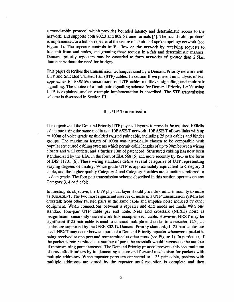
For an m-ary transmission scheme, the signal to NEXT ratio may be calculated as follows.Consider the block diagram shown in Figure 2. We assume that the equalizer compensates
3
Data source
Hdata(f)
,
NEXT loss
HNEXT(f)
Ir
Cable loss Data sourceEqualizer 1: I~- A(f) Hdata(f)
Figure 2: Block Diagram of UTP link with NEXT disturber.
for the cable loss and shapes the transmission channel response to have a raised cosineresponse of the form:
(I-a)= I forf <B~-~2
(1)
H (f) 0 5 ( I . (rtf rt)) c B (l - a) f B (l + a)chan =. X - SID Ba - 2a lor 2 < < 2
H (f) = 0 for f > B (I + a)chan 2
(2)
(3)
where f is frequency in Hz, B is the baud rate (symbols per second), and a is the excess
bandwidth factor (0::;;o s I). Crosstalk from a transmitter to a near end receiver is subjectto the NEXT loss between the transmitter and receiver, HNEXT(f), but is not subject to thecable loss, A(f). The NEXT noise channel is therefore given by:
H . (f) = H chan (f) X H NEXT (f)noise A (f)
4
(4)
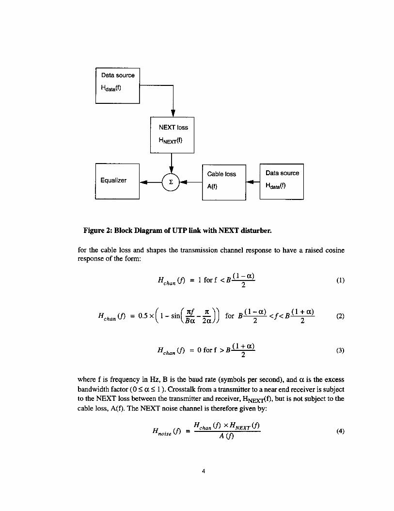
The noise voltage due to NEXT at the output of the receiver equalizer may be described interms of Hnoise(f) and the disturbing data source, Hdatif):
N (j) = Hnoise (j) X Hdata (j) X JW (5)
where W is the mean power transmitted by the data source. We next assume that the peaktransmit voltage, V, is constant for all schemes i.e. a binary scheme uses symbols of +V, V; a ternary scheme uses symbols of +V, 0, -V. This is a reasonable assumption becausethe power supply voltage available to any transmission scheme is generally fixed. For anm-ary scheme with a random choice of symbols the mean power transmitted by the datasource is:
(6)
The rms noise voltage due to NEXT is therefore:
=V( m + 1 )B oof (Hchan (j) X HNEXT(j) X Hdata (j))2df (7)vn 3(m-l) A(j)
We define the Signal to NEXT ratio (SINEXT) as:
~SINEXT =
. 2vn(8)
where ~ is the voltage separation between transmitted symbols. (Note that for an idealraised cosine channel the symbol voltage levels at the output of the channel will be equalto those at the input.) In general the separation.A, of the transmitted signal levels is 2V/(m1). Thus:
SINEXT = [(m-l) (m+l )B ooJ(Hchan(f) xHNEXT(f) XHdata(f))2dfJ-l (9)
3(m-l) A(f)-00
It is worth noting that the SINEXT ratio cannot be used to predict bit error rate, and henceabsolute system performance, in the usual way since crosstalk noise does not obeyGaussian statistics [8]. However, this ratio is still useful as a measure of the comparativeperformance of different transmission schemes. A more rigorous crosstalk analysis thatmay be used to predict absolute system performance is described in [9].
5
~ 15.0"0c:'irn"0.....5II)
10.0Q)
c..EcoII)
'0....Q).0E 5.0::JZ
80.0 100.020.0 40.0 60.0
NEXT Loss (dB)
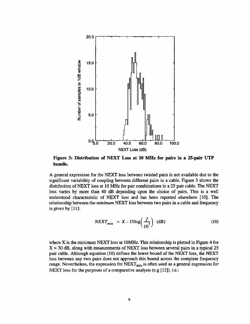
Figure 3: Distribution of NEXT Loss at 10 MHz for pairs in a 25-pair UTPbundle.
A general expression for the NEXT loss between twisted pairs is not available due to thesignificant variability of coupling between different pairs in a cable. Figure 3 shows thedistribution of NEXT loss at 10 MHz for pair combinations in a 25 pair cable. The NEXTloss varies by more than 40 dB depending upon the choice of pairs. This is a wellunderstood characteristic of NEXT loss and has been reported elsewhere [10]. Therelationship between the minimum NEXT loss between two pairs in a cable and frequencyis given by [11]:
NEXTmin = X -1510g( 1~7) (dB) (10)
where X is the minimum NEXT loss at 10MHz. This relationship is plotted in Figure 4 forX =30 dB, along with measurements of NEXT loss between several pairs in a typical 25pair cable. Although equation (10) defines the lower bound of the NEXT loss, the NEXTloss between any two pairs does not approach this bound across the complete frequencyrange. Nevertheless, the expression for NEXTmin is often used as a general expression forNEXT loss for the purposes of a comparative analysis (e.g [12]). i.e.:
6

80.0 rr----..---,-----.----r---..-----,
70.0
60.0
m50.0:E.
~40.0
30.0
20.0 30-15109(1/107)
30.010.0 20.0Frequency (MHz)
10.0 '-----'---"---..........--"'------'-----'0.0
Figure 4: Minimum NEXT loss and measured NEXT loss for pair combinationsin a 25-pair UTP bundle.
(11)
The maximum loss of a 100m voice-grade twisted pair is defined by the relationship [11]:
ATT = 232Jf + 0.238f (dB)max • 6 6
10 10(12)
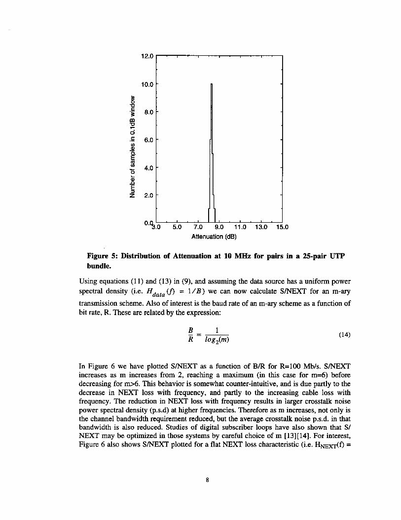
The attenuation of twisted pairs is much less variable than the NEXT loss, as confirmed bythe distribution shown in Figure 5 for a typical 25 pair cable. It is therefore appropriate touse equation (12) as a general expression for the cable loss.i.e.:
_!( 2.32Jj+ 0.238/ J2 4 7
A(j) = 10 10 10 (13)
7
10.0
~"'0c:
8.0.~
CO"'0....ci.5 6.0fIlellC.EasfIl 4.0-0....ell.0E::JZ 2.0
0''3.0 5.0 7.0 9.0 11.0 13.0 15.0
Attenuation (dB)
Figure 5: Distribution of Attenuation at 10 MHz for pairs in a 25-pair UTPbundle.
Using equations (11) and (13) in (9), and assuming the data source has a uniform power
spectral density (i.e. Hdata (f) = 1/B) we can now calculate SINEXT for an m-ary
transmission scheme. Also of interest is the baud rate of an m-ary scheme as a function ofbit rate, R. These are related by the expression:
(14)
In Figure 6 we have plotted SINEXT as a function of BIR for R=100 Mb/s. SINEXTincreases as m increases from 2, reaching a maximum (in this case for m=6) beforedecreasing for m>6. This behavior is somewhat counter-intuitive, and is due partly to thedecrease in NEXT loss with frequency, and partly to the increasing cable loss withfrequency. The reduction in NEXT loss with frequency results in larger crosstalk noisepower spectral density (p.s.d) at higher frequencies. Therefore as m increases, not only isthe channel bandwidth requirement reduced, but the average crosstalk noise p.s.d. in thatbandwidth is also reduced. Studies of digital subscriber loops have also shown that SINEXT may be optimized in those systems by careful choice of m [13][14]. For interest,Figure 6 also shows SINEXT plotted for a flat NEXT loss characteristic (i.e. HNEXT(t) =
8
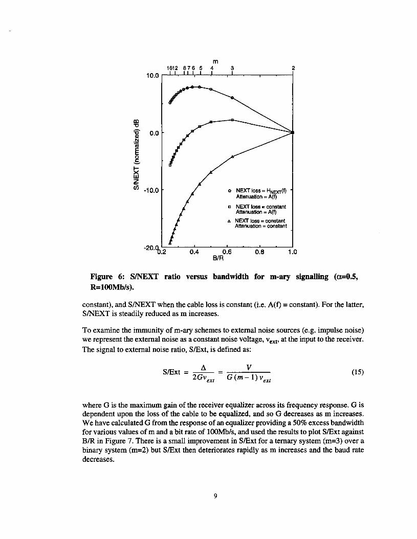
m1612 876 5 4 3 2
o NEXT loss = HNexr(f)Attenuation = A(f)
D NEXT loss= constantAttenuation = A(f)
I:.. NEXT loss = constantAttenuation =constant
m"0
S 0.0.~n;El5~ -10.0
-20'%.2 0.4 0.6BIR
0.8 1.0
Figure 6: SINEXT ratio versus bandwidth for m-ary signalling (a=O.S,R=l00Mb/s).
constant), and SINEXT when the cable loss is constant (i.e. A(f) = constant). For the latter,SINEXT is steadily reduced as m increases.
To examine the immunity of m-ary schemes to external noise sources (e.g. impulse noise)we represent the external noise as a constant noise voltage, vext ' at the input to the receiver.The signal to external noise ratio, SlExt, is defined as:
(15)V
G (m-l) vext
i1SlExt = 2~G=--- = ~~---:-:--
vext
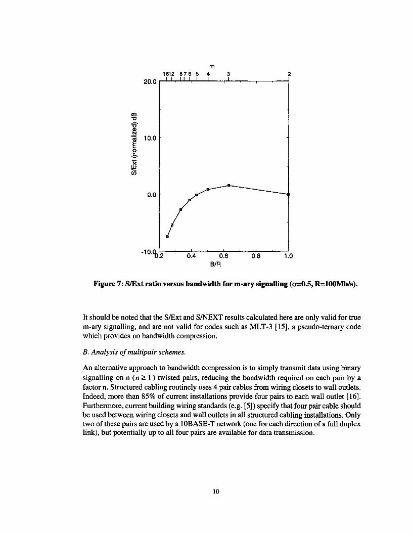
where G is the maximum gain of the receiver equalizer across its frequency response. G isdependent upon the loss of the cable to be equalized, and so G decreases as m increases.We have calculated G from the response ofan equalizer providing a 50% excess bandwidthfor various values of m and a bit rate of lOOMb/s, and used the results to plot SlExt againstBIR in Figure 7. There is a small improvement in SlExt for a ternary system (m=3) over abinary system (m=2) but SlExt then deteriorates rapidly as m increases and the baud ratedecreases.
9
m1612 876 5 4 3 2
tn"0
'SQ)
.!::l(ij 10.0E0.s><w-en
0.0
-10'%.2 0.4 0.6BIR
0.8 1.0
Figure 7: SlExt ratio versus bandwidth for m-ary signalling (a=O.5, R=l00Mb/s).
It should be noted that the SlExt and SINEXT results calculated here are only valid for truem-ary signalling, and are not valid for codes such as MLT-3 [15], a pseudo-ternary codewhich provides no bandwidth compression.
B. Analysis ofmultipair schemes.
An alternative approach to bandwidth compression is to simply transmit data using binarysignalling on n (n ~ 1) twisted pairs, reducing the bandwidth required on each pair by afactor n. Structured cabling routinely uses 4 pair cables from wiring closets to wall outlets.Indeed, more than 85% of current installations provide four pairs to each wall outlet [16].Furthermore, current building wiring standards (e.g. [5]) specify that four pair cable shouldbe used between wiring closets and wall outlets in all structured cabling installations. Onlytwo of these pairs are used by a 1OBASE-T network (one for each direction of a full duplexlink), but potentially up to all four pairs are available for data transmission.
10

0.80.6BIR
0.40.0.2
20.0
El Multipair signalling
o Multilevel signalling
15.0al"0
'SQ)N
faE 10.00c:-~w:E:en
5.0
Figure 8: SINEXT ratio versus bandwidth for multipair and multilevel signalling(a.=O.5, R=l00Mb/s).
Equation (9) may be used to calculate SINEXT of an n-pair binary signalling scheme, withm=2 and B=Rln. For multipair signalling, the expression for minimum NEXT loss ismodified to account for the presence of multiple disturbing pairs when n>1:
-xr: 20( f )0.75
H NEXT (j) = -m x 10 107 (16)
We assume here that the NEXT power loss due to multiple disturbers is inverselyproportional to the number of disturbers. This is a pessimistic assumption since it isunlikely that all disturbers simultaneously exhibit the minimum NEXT loss. Other, lesspessimistic, multiple disturber models have been used (e.g. [13], [14]), in which themultiple disturber NEXT power loss scales by some factor less than n.
Figure 8 shows SINEXT plotted against BIR for a 100 Mb/s multipair scheme. SINEXTincreases as the number of pairs increases since the more severe crosstalk at higherfrequencies is avoided by reducing the bandwidth per pair. At the same time the symbolseparation, ~, remains at the maximum value of 2V as n increases. SINEXT for m-ary
11
20.0 .......---,.....----,----.----,.---.---.,...-........-....,
m"0
~.~(ij 10.0Eo.s
~
0.0
o Multipair signalling
o Multilevel signalling
m=2n=1
0.4 0.6BIR
0.8 1.0
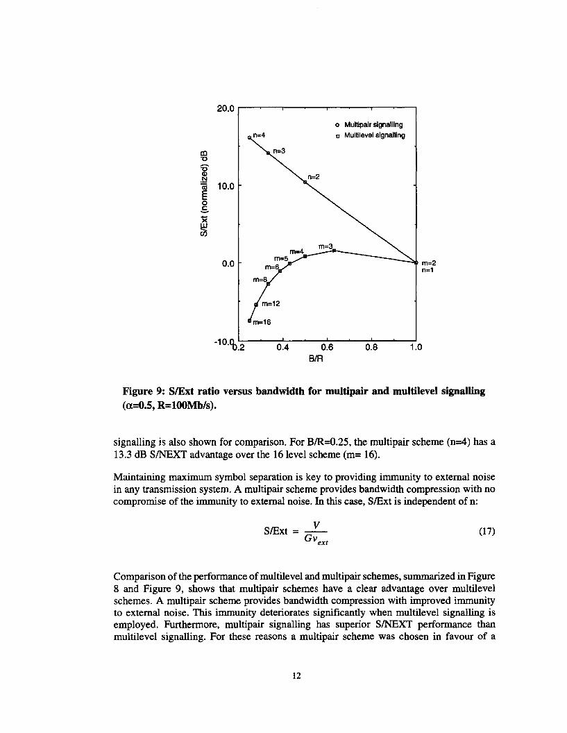
Figure 9: SlExt ratio versus bandwidth for multipair and multilevel signalling(a=O.5, R=l00Mb/s).
signalling is also shown for comparison. For BIR=O.25, the multipair scheme (n=4) has a13.3 dB SINEXT advantage over the 16 level scheme (m= 16).
Maintaining maximum symbol separation is key to providing immunity to external noisein any transmission system. A multipair scheme provides bandwidth compression with nocompromise of the immunity to external noise. In this case, SlExt is independent of n:
VSlExt =-
GVext
(17)
Comparison of the performance of multilevel and multipair schemes, summarized in Figure8 and Figure 9, shows that multipair schemes have a clear advantage over multilevelschemes. A multipair scheme provides bandwidth compression with improved immunityto external noise. This immunity deteriorates significantly when multilevel signalling isemployed. Furthermore, multipair signalling has superior S/NEXT performance thanmultilevel signalling. For these reasons a multipair scheme was chosen in favour of a
12
multilevel scheme for the Demand Priority UTP physical link. UTP links are half duplex,with data being transmitted on all four pairs of a cable.
C. Block coding
Connections to twisted pair links are typically made via transformers. The data spectrummust therefore be shaped in some way to account for the lack of a d.c. path through thesetransformers and avoid severe signal degradation due to baseline wander [17]. A 5B6Bblock code is used [18], which has a spectral null at d.c. and incurs relatively littlebandwidth expansion (20%). Hence, for a 100 Mb/s four pair scheme, the transmission rateper pair increases from 25 Mb/s to 30 Mb/s due to 5B6B coding.
Close to perfect d.c. balance (i.e. an equal number of +V and -v symbols transmitted) isachieved as follows: Twenty of the required six bit codewords are balanced, consisting ofthree ones and three zeros (or, after NRZ coding, three +V and three -V symbols). Theremaining twelve six bit codewords must be unbalanced, and are chosen from one of twosets. The first set consists of "weight-2" codewords, having 2 ones and four zeros. Thesecond set consists of "weight-4" codewords having four ones and two zeros. Whenever anunbalanced codeword is needed, the "weight-2" and "weight-4" sets are used alternately,starting with the "weight-2" set. The maximum imbalance at the end of any codewordoccurs when the number of zeros that have been transmitted exceeds the number of onesby two. The running digital sum (r.d.s) is bounded such that -5 $ r.d.s $ 3 [19].
The particular 5B6B code chosen for Demand Priority networks ensures good transitiondensity, with a maximum run-length of 6 bits. Coupled with a CRC-32 frame check [20],this particular code also meets the IEEE requirement for any LAN, that no undetectablepacket errors shall occur due to 3 or less single bit errors [21].
D. Implementation
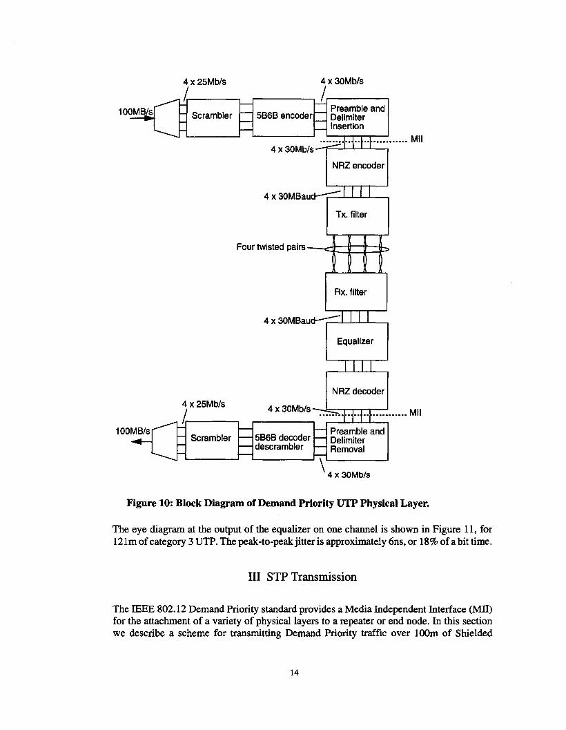
A block diagram of a Demand Priority UTP physical link implementation is shown inFigure 10. At the transmitter, quintets of data are split between four channels prior toscrambling and 5B6B coding. Scrambling is not required for d.c. balance, as this isprovided by the block code, but does increase the probability of a random selection ofcodewords. This helps to avoid possible problems with radiated emissions when discretespectral lines are generated due to repetitive transmission of a single codeword.
Preamble, start- and end-of-sequence patterns are added to each channel before the codeddata is passed to a transceiver chip. An example of a transceiver is the AT&T T7380 chip[22] which NRZ codes and transmits the data using symbol levels of +/-2.5V. One 5th orderButterworth filter (3dB point at 20MHz) per pair is used for both transmit and receivefiltering, depending upon the direction of transmission. A simple, analog, adaptiveequalizer is used in the receiving transceiver to compensate for varying lengths ofcable andminimize intersymbol interference on each channel. The recovered data is decoded and thequintets from the four channels are assembled into the original data stream.
13
4 x 25Mb/s
1.----.Scrambler
4 x 30Mb/s
,..-----, /.-------.Preambleand
5666 encoder DelimiterInsertion
.••••••••••••••••••••••• Mil4 x 30Mb/s--==:::::...L-L-L--'--..
NRZ encoder
4 x30M6au~....................."""-----,
Tx. filter
Four twisted pairs--c:::t::::v:=t~p
Rx. filter
4 x 30M6auc:t-:::::::...................L.....--.
Equalizer
NRZ decoder
PreambleandDelimiterRemoval
\4 x 30Mb/s
4 x 30Mb/s-::-s Mil
5666 decoderdescrambler
Scrambler
4 x 25Mb/s
I.r------,
Figure 10: Block Diagram of Demand Priority UTP Physical Layer.
The eye diagram at the output of the equalizer on one channel is shown in Figure 11, for121m ofcategory 3 UTP. The peak-to-peakjitter is approximately 6ns, or 18% ofa bit time.
III STP Transmission
The IEEE 802.12 Demand Priority standard provides a Media Independent Interface (MIT)for the attachment of a variety of physical layers to a repeater or end node. In this sectionwe describe a scheme for transmitting Demand Priority traffic over 100m of Shielded
14
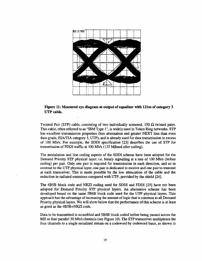
Figure 11: Measured eye diagram at output of equalizer with 121m of category 3UTP cable.
Twisted Pair (STP) cable, consisting of two individually screened, 150 n twisted pairs.This cable, often referred to as "IBM Type 1", is widely used in Token Ring networks. STPhas excellent transmission properties (less attenuation and greater NEXT loss than evendata-grade, EIA!fIA category 5, UTP), and is already used for data transmission in excessof 100 Mb/s. For example, the SDDI specification [23] describes the use of STP fortransmission ofFDDI traffic at 100 Mb/s (125 MBaud after coding).
The modulation and line coding aspects of the SDDI scheme have been adopted for theDemand Priority STP physical layer; i.e, binary signalling at a rate of 100 Mb/s (beforecoding) per pair. Only one pair is required for transmission in each direction, and so incontrast to the UTP physical layer, one pair is dedicated to receive and one pair to transmitat each transceiver. This is made possible by the low attenuation of the cable and thereduction in radiated emissions compared with UTP, provided by the shield [24].
The 4B5B block code and NRZI coding used for SDDI and FDDI [25] have not beenadopted for Demand Priority STP physical layers. An alternative scheme has beendeveloped based on the same 5B6B block code used for the UTP physical layers. Thisapproach has the advantage of increasing the amount of logic that is common to all DemandPriority physical layers. We will show below that the performance of this scheme is at leastas good as the 4B5B+NRZI code.
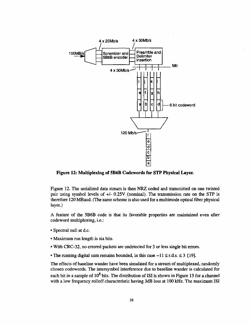
Data to be transmitted is scrambled and 5B6B block coded before being passed across theMIl as four parallel 30 Mb/s channels (see Figure 10). The STP transceiver multiplexes thefour channels to a single serialized stream on a codeword by codeword basis, as shown in
15
4 x25Mb/s 4 x30Mb/s
1..------, 1..--------.Scramblerand Preambleand5868 encoder Delimiter
Insertion
4 x 30Mb/s...:;..•••••••••T ,Mil
k
edcba
Figure 12: Multiplexing of 5B6B Codewords for STP Physical Layer.
Figure 12. The serialized data stream is then NRZ coded and transmitted on one twistedpair using symbol levels of +/- 0.25V (nominal). The transmission rate on the STP istherefore 120 MBaud. (The same scheme is also used for a multimode optical fiber physicallayer.)
A feature of the 5B6B code is that its favorable properties are maintained even aftercodeword multiplexing, i.e.:
• Spectral null at d.c.
• Maximum run length is six bits.
• With CRC-32, no errored packets are undetected for 3 or less single bit errors.
• The running digital sum remains bounded, in this case -11 :s; r.d.s. :s; 3 [19].
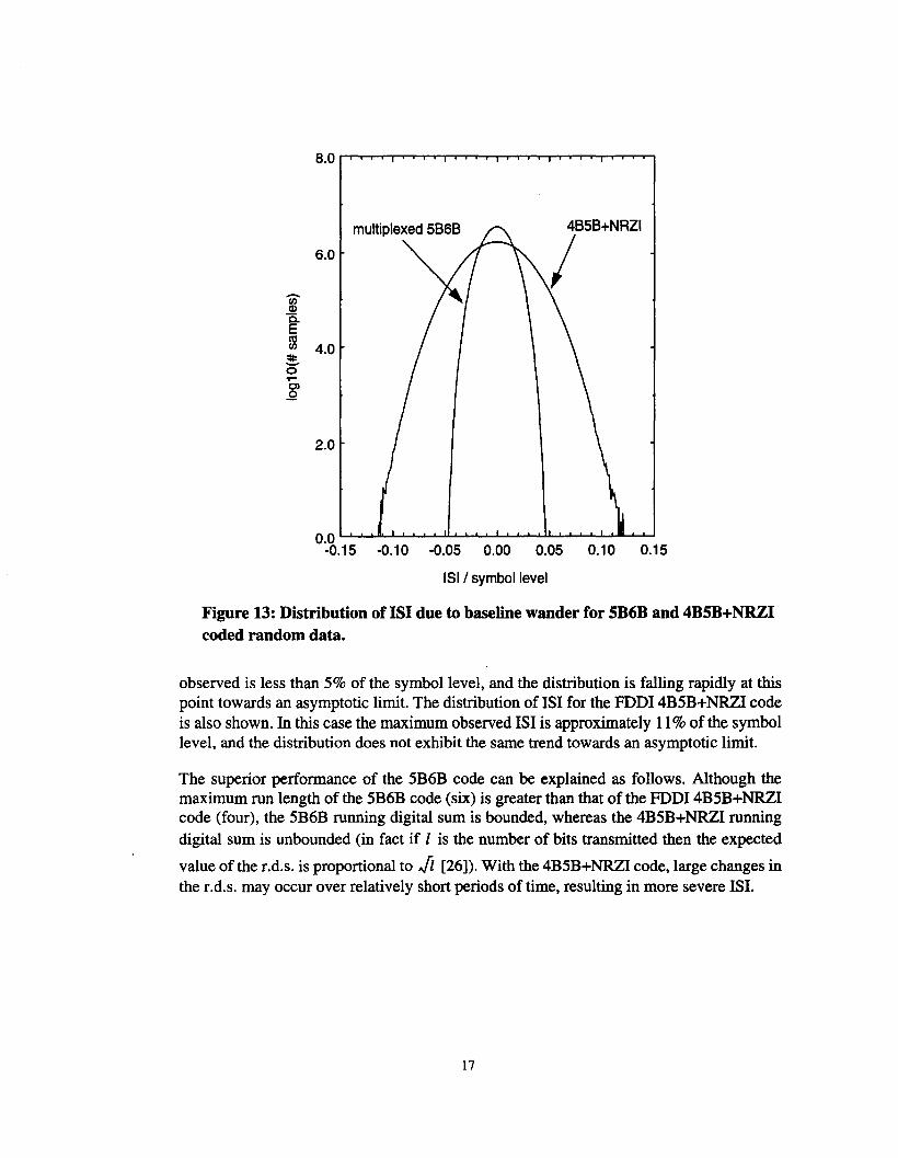
The effects of baseline wander have been simulated for a stream of multiplexed, randomlychosen codewords. The intersymbol interference due to baseline wander is calculated for
each bit in a sample of 108 bits. The distribution of lSI is shown in Figure 13 for a channelwith a low frequency rolloff characteristic having 3dB loss at 100kHz. The maximum lSI
16
4B5B+NRZI
6.0 Ili)Q)
C.Eco(/) 4.0~0.....C)
.Q
2.0
0.0 ~~II-L. ....LL...l--'-' ~ ...........
-0.15 -0.10 -0.05 0.00 0.05 0.10 0.15
151 / symbol level
Figure 13: Distribution of lSI due to baseline wander for 5B6B and 4B5B+NRZIcoded random data.
observed is less than 5% of the symbol level, and the distribution is falling rapidly at thispoint towards an asymptotic limit. The distribution of lSI for the FODI 4B5B+NRZI codeis also shown. In this case the maximum observed lSI is approximately 11% of the symbollevel, and the distribution does not exhibit the same trend towards an asymptotic limit.
The superior performance of the 5B6B code can be explained as follows. Although themaximum run length of the 5B6B code (six) is greater than that of the FODI 4B5B+NRZIcode (four), the 5B6B running digital sum is bounded, whereas the 4B5B+NRZI runningdigital sum is unbounded (in fact if 1 is the number of bits transmitted then the expected
value of the r.d.s. is proportional to Ji [26]). With the 4B5B+NRZI code, large changes inthe r.d.s. may occur over relatively short periods of time, resulting in more severe lSI.
17
IV Summary
We have described two data transmission schemes that have been developed to carry 100Mb/s IEEE 802.12 Demand Priority traffic over Unshielded Twisted Pair and ShieldedTwisted Pair cables commonly found in current network infrastructures. The UTP schemesupports category 3,4 and 5 UTP (i.e. voice-grade and data-grade) using a 5B6B blockcoded binary signalling scheme on four pairs. The Signal-to-NEXT and Signal-to-ExternalNoise ratios for this scheme have been calculated and compared with multilevel (m-ary)signalling techniques. The binary signalling scheme provides the maximum immunityagainst crosstalk and external (impulse) noise, maintaining the robustness of the widelysuccessful 1OBASE-T network.
The STP scheme combines the strengths of the 5B6B block code with signallingtechnology similar to existing SDDI links: i.e binary NRZ signalling on a single pair perdirection. The lSI due to baseline wander of the multiplexed 5B6B code has been shown tobe less than that of the SDDIIFDDI 4B5B+NRZI code.
V References
[1] "Data Networking Trends: User Perspectives Survey", Datapro Information ServicesGroup, December 1993.
[2] "PC LAN Cabling Split by Media Type: Worldwide Forecast, 1989 to 1995",International Data Corporation, August 1991.
[3] "Demand Priority Access Method and Physical Layer Specifications, Draft 4.0", IEEEDraft Standard P802.12/D4.
[4] A. Albrecht, J. Curcio, D. Dove, S. Goody, M. Spratt, "An Overview of IEEE 802.12Demand Priority", Proceedings of Globecom 1994, San Francisco, 1994.
[5] "The Commercial Building Telecommunications Wiring Standard", EIA!fIA-568Standard, July 1991.
[6] "Generic Cabling for Customer Premises", ISOIIEC DIS 11801 Draft InternationalStandard.
[7] "Twisted Pair Medium Attachment Unit (MAU) and Baseband Medium, TypelOBASE-T", IEEE Standard 802.3, section 14.4.4.1.
[8] R.J.S. Bates, P. Cochrane, "Method of estimating the capacity of multipair cables tocarry low-speed p.c.m. transmission systems", lEE Proceedings, Part F, 127, Feb. 1980, pp.16-21.
[9] A.N. Coles, "Crosstalk Analysis for High Speed Twisted Pair Transmission in LocalArea Networks", to be published.
18

[10] "Transmission Systems for Communications", Fifth Edition, Bell TelephoneLaboratories, 1982.
[11] "Commercial Building Telecommunications Cabling Standard", EIAlfIA SP 2840-Aproposed revision of EIA!fIA-568.
[12] Gi-Hong Im, J.1. Werner, "Bandwidth-Efficient Digital Transmission up to 155 Mb/sover Unshielded Twisted Pair Wiring", Proceedings of ICC'93, Geneva, 1993.
[13] P. Crespo, "Performance Analysis of Baseband Multilevel Transmission Schemes inDigital Subscriber Loops in the Presence of Near-End Crosstalk." Int. J. of Digital andAnalog Comm. Sys., Vol. 3, 1990, pp. 287-295.
[14] G. Brand, V. Madisetti, D.G. Messerschmitt, "Multilevel RangelNEXT Performancein Digital Subscriber Loops", lEE Proc I, Vol. 136, Apri11989, pp. 169-174.
[15] ANSI X3T12, "FDDI twisted pair physical layer medium dependent (TP-PMD)",American National Standard, 1994.
[16] J. Payne, "End User Cabling Survey", Presented to IEEE 802.3 High Speed WorkingGroup, Boston, May 1993.
[17] "Digital Communication", E.A. Lee, D.G. Messerschmitt, second edition, KluwerAcademic, 1994.
[18] 1. Jedwab, "Error Detection in 100Base-VG", Presented to IEEE 802.3 High SpeedWorking Group, January 1993.
[19] S. Crouch, "Multiplexing and Error Detection", Presented to IEEE 802.12 WorkingGroup, Irvine, September 1993.
[20] W. Petersen and E. Weldon, "Error Correcting Codes", Cambridge, M.I.T. Press,1972.
[21] J. Jedwab, "IEEE 802 Functional Requirement", Presented to IEEE 802.3 High SpeedWorking Group, March 1993.
[22] "T7380 Twisted-Pair Transceiver Chip", AT&T Microelectronics Data Sheet.
[23] "SDDI: A specification forFDDI on Shielded Twisted Pair", Implementors agreementpublished by AMD Inc., Chipcom Corp., mM Corp., Madge Networks Inc., Motorola Inc.,National Semiconductor Corp., Network Peripherals, Inc., Sumitomo Corp., SynopticsCommunications Inc., SysKonnect Inc., and Technitrol Inc.
[24] H. Blennemann and L. Haas, "Performance of Proposed 802.12 STP Solution",Presented to IEEE 802.12 Working Group, Vancouver, March 1994.
[25] "Fiber Distributed Data Interface (FDDI) - Token Ring Physical Layer Protocol(PHY)", ANSI X3.148-1988 standard.
[26] S.E.C. Crouch, private communication.
19