10 measurements - digital.library.unt.edu/67531/metadc622920/m2/1/high...direct laser irradiation...
TRANSCRIPT

UCRL- JC-120734 PREPRINT
The Pressure Re ime 10 -750 MBAR Use of Lasers in % OS Measurements
R. Cauble L. B. Da Silva B. A. Hammel N. C. Holmes
R. W. Lee T. S. Perry
D. W. Phillion
University of California Lawrence Livermore National Laboratory
This paper was prepared for publication in the Proceedings of the 15th International Conference of the Association for the Advancement of High Pressure Science and Technology
Warsaw, Poland, September 11-15,1995
September 1995
BER
DISCLAIMER
This document was prepared as an account of work sponsored by an agency of the United States Government Neither the United States Government nor the University of California nor any of their employees, makes any warranty, express or implied, or assumes any legal liability or responsibility for the accuracy, completeness, or usefulness of any information, apparatus, product, or process disclosed, or represents that its use would not infringe privately owned rights. Reference herein to any specific commerciaI product, process, or service by trade name, trademark, manufacturer, or otherwise, does not necessarily constitute or imply its endorsement, recommendation, or favoring by the United States Government or the University of California- The views and opinions of authors expressed herein do not necessariiy state or reflect those of the United Stam Government or the University of California, and shall not be used for advertising or product endorsement purposes.

THE PRESSURE REGIME 10 - 750 MBAR: USE OF LASERS IN EOS MEASUREMENTS
R. CAUBLE, L. B. DA SILVA, 8. A. HAMMEL, N. C. HOLMES, R. W. LEE, T. S. PERRY and D. W. PHILLION
University of California, Lawrence Livermore National Laboratory Livermore, CA 94550 USA
ABSTRACT
The use of intense lasers has lon been proposed as a means to generate Mbar pressures in matter
k%kf%& to produce a uniform shock. Recentl the use of smooth laser beams and indirect drive have led to the reliable production of &m > 10 Mbar shocks in solids over > 0.5 mm surface. Direct laser irradiation can produce shock pressures up to = 30 Mbar. Indirect irradiation using hi h-Z hohlraums cah exceed 100 Mbar. Accelerated foils, where the driver is an indirect x-ra fiek produced by a k i l o j o d d s s laser, have produced ressures of 750 Mbar. his opens the &or to use high power lasers for EOS studies. It is PredicteBtthat a megajouldss laser, such as NE, will be able to produce energy densities an order of magnitude greater than these
for the study of high energy 3 ensi uations-of-state. Ths effort has been hampeied by mainly by the small s p a d s a e s necessary to obtain the IEXJU.& high intensities and .
Introduction
There is a great' deal of uncertainty in equations-of-state for pressure regimes greater than a few Mbar, although there are many astrophysical and terrestrial problems involving this apparently extreme regime. In particular, one earthly example is the prediction of Gbar pressures in spherically compressed capsules typical of inertial confinement fusion targets.1 In the limiting case of extremely high pressure, the EOS is described by a Thomas-Fermi model; however the regime of applicabiiity and approach to this limit are not known. and, for metals, this model may not be valid for pressures under several Gbar.2 Fig. 1 shows a plot of several EOS model principal Hugoniots for a l ~ m i n u m ; ~ note the uncertainty in the Hugoniot for a metal long used as a standard in EOS measurements. The reason for this uncertainty is the limited amount of EOS data at pressures above = 3-4 Mbar because of the difficulty in producing high pressure conditions and simultaneously measuring relevant parameters. We consider here the use of high intensity lasers for achieving these conditions.
ldr
3 4 5 Compression
Figure 1. Plot taken from Ref. 3 showing aldinum Hugoniots predicted by seven currently-used EOS models. Note the considerable variation near one Gbar.
Directly Driven High Pressure Shocks
It was recognized more than two decades ago that high intensity lasers would provide access to
.
multi-Mbar energy density regime. Dimensional arguments suggest that the pressure in a solid obtained by a laser driven shock can be estimated as4
where I14 is the laser intensity in units of 1014 W/cm2 and hpm is the laser wavelength in units of microns. Although this formula generally overestimates the pressure, it is readily seen that conventional lasers focused to high intensities can achieve multi-Mbar conditions. To be useful for EOS measurements, however, additional criteria must be met. It is desirable that the shock be planar, rather than in a convergent geometry, to make measurements and interpretation easier. The shock must be spatially uniform, steady on the timescale of the diagnostics and the initial material conditions accurately known (meaning that the material cannot be subject to preheat). Early attempts to use lasers as shock drivers for potential EOS experiments5 met with the following problems: 1) the laser beam was not sufficiently smooth, thus structure in the beam drove unpredictable, highly modulated shocks into the material; 2) laser structure also produced hot spots which led to suprathermal electrons and high energy x rays which heated the material before shock arrival (preheat); and 3) high intensities required tight focusing and thus small laser spots (= 100 pm) resulting in shocks that were not planar. Although pressures of 10 - 100 Mbar were d e t e ~ t e d , ~ , ~ all of the above difficulties compromised direct laser irradiation as an EOS tool.
The laser beam far field can be smoothed with the use of a random phase plate (RPP), dramatically reducing intensity structure and hot spots.7 We have used a plate with hexagonal phase plate elements 3 mm in diameter producing a far field which is nearly an Airy pattern with a 1 mm zero-to-zero diameter and a characteristic speckle size of 6 pm. Since such a sharply peaked spot would not provide the planar conditions needed in our experiment, steering
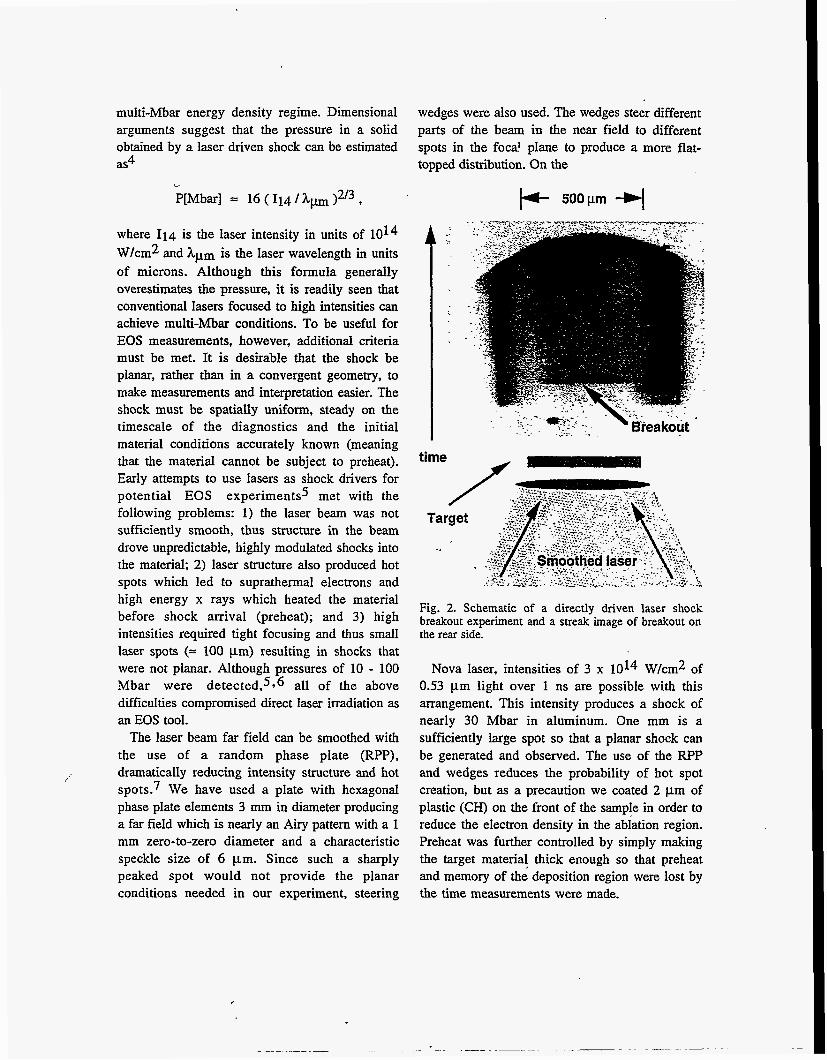
wedges were also used. The wedges steer different parts of the beam in the near field to different spots in the foca? plane to produce a more flat- topped distribution. On the
p- 5 0 0 w -q
time - Fig. 2. Schematic of a directly driven laser shock breakout experiment and a streak image of breakout on the rear side.
Nova laser, intensities of 3 x 10¹⁴ W/cm2 of 0.53 pm light over 1 ns are possible with this arrangement. This intensity produces a shock of nearly 30 Mbar in aluminum. One mm is a sufficiently large spot so that a planar shock can be generated and observed. The use of the RPP and wedges reduces the probability of hot spot creation, but as a precaution we coated 2 pm of plastic (CH) on the front of the sample in order to reduce the electron density in the ablation region. Preheat was further controlled by simply making the target material thick enough so that preheat and memory of the deposition region were lost by the time measurements were made.

'Fig. 2 shows a streak of a shock breakout on the rear side of a 25 pm thick aluminum disk; the image was made with a UV streak camera. Temporal variation of the breakout indicates that the shock is planar across the disk by less than lo; an extremely planar shock.8
Indirectly Driven High Pressure Shocks
Using lasers, high pressure shocks can be created with excellent uniformity by converting the laser light to x rays by the use of a high-2 secondary target, such as a foil. The laser irradiates the foil which then emits x rays in a broad frequency band. Some energy is lost in the laser-to-x-ray-field conversion process so that drive intensity is sacrificed for drive uniformity. Much of the intensity can be recovered by irradiating the interior of a hohlraum instead of an open foil. Laser energy is deposited into a metallic cavity where it is absorbed and re- radiated; the resulting energy source has a broad- spectrum and is very uniform. Although much of the laser energy is lost to the walls of the hohlraum, the result is a radiation drive with near- black-body characteristics at effective temperatures of 100 - 300 eV.9 The drive has been smoothed by interactions inside the hohlraum and is not at a single frequency, thus it is smoother than direct laser irradiation.1° Shock pressures of more than 100 Mbar can be obtained with millimeter-scale cylindrical gold hohlraums irradiated by 25 kJ of 0.35 pm light. Both direct drive and indirect drive can be used in impedance match EOS measurements: there is sufficient room to accommodate both the standard and the sample.
Colliding Foil Experiments
Lasers can be used as drivers in a variation and miniaturization of the well known flyer plate technique-l In this method, the flyer, here a foil, stores energy from the driver over an acceleration time and delivers it rapidly as thermal energy in collision with another foil. In addition, the flyer acts as a preheat shield. This technique was
demonstrated using a laser in a directly driven arrangement to achieve pressures of more than 100 Mbar.12
However, directly driven foils have the same ' problems as discussed earlier with direct drive shocks. Recently, it was shown that even with a smoothed laser beam, micron-scale intensity fluctuations in the beam causes the foil, typically very thin, to break up on the scale of the f l~ctuat i0ns. l~ Thus the flyer foil becomes a set of streaming plasma jets.
fc 700pm +I
Time
Fig. 3. Experimental schematic and a streak result of a hohlraum driven colliding foil experiment at Nova. The pressure inferred on the target was 750 Mbar.
A set of flyer foil experiments was conducted at Nova using a millimeter-scale gold hohlraum so that the flyer would be indirectly, rather than directly, a~ce1erated.l~ The setup and a streak result are seen in Fig. 3. Shock uniformity was demonstrated by breakout measurements. The

hohlraum x-rays ablate a CH layer to which is attached a 3:mm-thick gold foil. This flyer foil accelerates through a void region and, near the end of the laser pulse and collides with a stepped stationary gold target foil.
The shock velocity was obtained by measuring the breakout on the two steps. The measured average shock velocity was 70 k 6 km/sec implying a density of 90 g/cm3 and a pressure of 0.75 Gbar in the target, which remains the highest planar pressure produced without the aid of a nuclear weapon. If the density of the flyer could be determined at impact, Hugoniot measurements could be made in this regime.14
Indirectly Driven Hugoniot Experiments on Polystyrene
Plastics are very different materials than ahminum or gold, but they are just as pervasive in ICF experiments as major constituents of spherical capsule targets. Since plastics, unlike metals, are largely transparent to high energy x rays, x rays can be used to backlight relatively thick samples of CH and provide information on the sample as a function of time. In particular, the
Backlighter
Fig. 4. Experimental setup for performing two parameter Hugoniot measurements on plastic. A streak camera records x-ray transmission showing shock and contact interface motion.
shock front in a sample of CH can be seen on a streak camera by simultaneously imaging the transmission of an x-ray backlighter through the shocked and unshocked material; the transmission through the denser, shocked CH is significantly less than through normal density CH (about 70% less for a compression of 4 in a 0.7 mm thick sample using a 7 keV backlighter energy). If, at the same time, motion of the material behind the shock can also be imaged, Hugoniot data can be directly obtained without having to compare to a standard.
An experimental arrangement which accomplishes this is depicted in Fig. 4. The material motion behind the shock is viewed as the difference in transmission of the backlighter through shocked, doped CH and shocked undoped CH, this is the interface shown in the figure. The drive is provided by a hole in the side of a gold hohlraum. Eight beams of Nova are used for the drive, saving two beams for the ba~k1ighter.l~
Predicted shock pressure is controlled by varying the thickness of the doped CH layer. The regime from = 10 Mbar to = 40 Mbar has so far been explored. [Higher pressures have not yet been examined because the interface must be protected from preheat-causing x rays emanating from the hohlraum. Although the 2% bromine dopant in the first CH section serves as a preheat shield, predominant protection is provided by additional mass in a long first section. This means that the shock is decaying upon arrival at the interface. Measurements can be made with sufficient speed to obviate problems caused by the decaying shock.] The backlight beam was initiated near the time the shock arrived at the interface. It is necessary to view the shock as it passes through the interface as well as the interface as it picks up speed behind the shock front. This is because the shock speed and the interface speed will likely decay at different rates. Data from these experiments are still being analyzed. However, we expect there to be sufficiently clear results to be able to differentiate different EOS models.

We can scale these results to a next-generation, megajoule-class laser, such as the National Ignition Facility planned for Livermore or the megajoule laser, planned for Bordeaux. Large-scale, hohlraum driven shocks will be possible with drive pressures near one Gbar. Pressures reached in a flyer foil experiment are predicted to be near 10 Gbar, an order of magnitude higher energy density than presently available in the laboratory.
AcknowIedgments
This work was performed under the auspices of the US Department of Energy by LLM, under Contract NO. W-7405-ENG-48.
References
1. John D. Lindl, Robert L. McCrory, and E. Michael Campbell, Physics Today 45, No.9, 32 (1992).
2. A. V. Bushman and V. E. Fortov, Sov. Phys. Usp. 26, 465 (1984).
3. E. Avrorin et al., Sov. Physics JETP 66, 348 (1987).
4. Th. Lower and R. Sigel, Contrib. Plas. Phys. 33, 355 (1995).
5. L. R. Veeser and J. C. Solem, Phys. Rev. Lett. 40, 1391 (1978); R. J. Trainor et al., Phys.
Rev. Lett. 42, 1154 (1979); F. Cottet et af., Phys. Rev. Lett. 52, 1884 (1984).
6. N. C. Holmes et al., in Proceedings of 8th AIRAPT and 19th EHPRL Conference, eds. C. M. Backman, T Johannisson, and L. Then& (Uppsala, 1981); F. Cottet, App. Phys. Lett. 47, 678 (1985); J. D. Kilkenny, in Laser Program Annual Report, 1986, UCRL 50021- 86 (1987), p. 3.
7, S. Skupsky et al., J. Appl. Phys. 66, 3456 (1989).
8, R. Cauble et al., ICF Quarterly Report 3,
9. S. Sakabe et al., Phys. Rev. A 38, 5756 (1988); G. D. Tsakiris and R. Sigel, Phys. Rev. A 38, 5769 (1988); R. Sigel et al., Phys. Rev. A 38, 5779 (1988).
10. Th. Lower et al., Phys. Rev. Lett. 72 3186 (1994).
11. L. V. Al'tshuler et' al., Sov. Phys. JETP 7, 606 (1958). ,
12. S. P. Obenschain et al., Phys. Rev. Lett.. 50, 44 (1983); R. Fabbro, et al., Laser Part. Beams 4, 413 (1986).
13. R. Cauble et al., Phys. Rev. Left. 74, 3816
14. R. Cauble, et al., Phys. Rev. Lett. 70, 2102 (1993).
15 B. A. Hammel, et al., Phys. Fluids B 5, 2259 (1993).
UCRL-LR-105821-93-3 (1993), p. 131.
(1995).
