1.0 introduction 1.1 background...
TRANSCRIPT
DESIGN OF A DIVERSION WEIR
F21/0029/2008 Page 1
1.0 INTRODUCTION
1.1 Background Information
Irrigation is an artificial application of water to the soil through various systems of tubes, pumps,
and sprays. Irrigation is normally used in areas where rainfall is inconsistent or dry conditions or
drought is expected (Frenken, K. (2005)).
Irrigation can also be defined as the process of supplying water, in addition to natural
precipitation, to field crops, orchards, vineyards, or other cultivated plants. Irrigation water is
applied to ensure that the water available in the soil is sufficient to meet crop water needs. The
role of irrigation is to improve production and the effectiveness of other inputs.
Irrigation has the following purposes:
• Providing insurance against short duration droughts
• Reducing the hazard of frost (increase the temperature of the plant)
• Reducing the temperature during hot spells
• Washing or diluting salts in the soil Softening tillage pans and clods
• Delaying bud formation by evaporative cooling
• Promoting the function of some micro organisms
It has also been found to have the following benefits:
1. Increase in Crop Yield
2. Protection from famine
3. Cultivation of superior crops
4. Elimination of mixed cropping
5. Economic development
6. Hydro power generation
7. Domestic and industrial water supply
The following are considered to be the objectives of irrigation:

DESIGN OF A DIVERSION WEIR
F21/0029/2008 Page 2
• To Supply Water Partially or Totally for Crop Need
• To Cool both the Soil and the Plant
• To Leach Excess Salts
• To improve Groundwater storage
• To Facilitate continuous cropping
• To Enhance Fertilizer Application- Fertigation
According to Frenken, K. (2005), irrigation systems can be classified as hereunder:-
1.1.1 Surface Irrigation- Surface irrigation methods use the soil surface to spread water across a
field or orchard to the plants being irrigated, and include furrow, border or flood irrigation and
basin irrigation.
1.1.2 Sprinkler Irrigation - In this type of irrigation water is applied to all field by means of
rotating sprinklers or mini-sprinklers connected to a pressurized pipe system
1.1.3 Micro- Irrigation - In micro irrigation water is applied to the plants through emitters so
that water leaves the emitter as a droplet. Water is supplied to the emitters through a network of
mainline and literal pipelines that are normally made of plastics.
1.1.4 Drip irrigation - Depending on how the emitters are placed in the plastic polyethylene
distribution line, the drip mode can be further delineated as a line source or a point source. The
line source type emitters are placed internally in equally spaced holes or slits made along the
line. Water applied from the close and equally spaced holes usually runs along the line and forms
a continuous wetting pattern.
1.1.5Localized Irrigation
Water is spread in low pressure, through a piped system and supplied to each plant.
1.1.6 Lateral Move Irrigation
Water is spread through a series of pipes, each with a wheel and a set of sprinklers, which are
rotated either by hand or with a purpose-built mechanism.
DESIGN OF A DIVERSION WEIR
F21/0029/2008 Page 3
1.2. Site Analysis and Inventory
Kirinyaga County can be divided into three ecological zones; the lowland area that lies between
1158 m to 2000 m above sea level, the midland area that lie between 2000m to 4000m above sea
level and the highland area that lies between 4800m to 6800m above sea level.
The lowland area is characterized by gentle rolling plains that cover most of kirinyaga South
district. The upper midland area covers the lower areas of Kirinyaga West and Kirinyaga East
districts.
The highland area covers the upper areas of Kirinyaga West, Kirinyaga East and Kirinyaga
Central districts and the whole of the mountain area of the county.
The county has a tropical climate and an equatorial rainfall pattern. This climatic condition is
influenced by the county’s position along the equator and its position on the wind ward side of
Mt Kenya. It has two rainy seasons, the long rains which occur from March to May and the short
rains which occur from October to November. The long rains average 710 mm while the short
rains average 640 mm. The amount of rainfall declines from the high altitude on the slopes of
Mt. Kenya towards the Semi-arid zones in the eastern part of Kirinyaga South district. The
temperature ranges from a mean of 8.10c in the upper zones with high attitude to 30.3
0c in the
lower zones with low attitudes during the hottest season.
Kirimara Irrigation Scheme is an irrigation scheme in Kirimara, which is a location in Mwea
Division of Kirinyaga County. This can be considered to be in Kirinyaga South District. I
idenfied the problems that the farmers in this scheme were undergoing during my fieldwork
attachment.
The proposed scheme is to be designed such that to accommodate a total of about 1,200 farmers
and provide for a future expansion of about 20%. The scheme is to get water from River
Nyamindi. The crops to be grown will be horticultural crops such as tomatoes, French beans,
some vegetables as well as bananas.
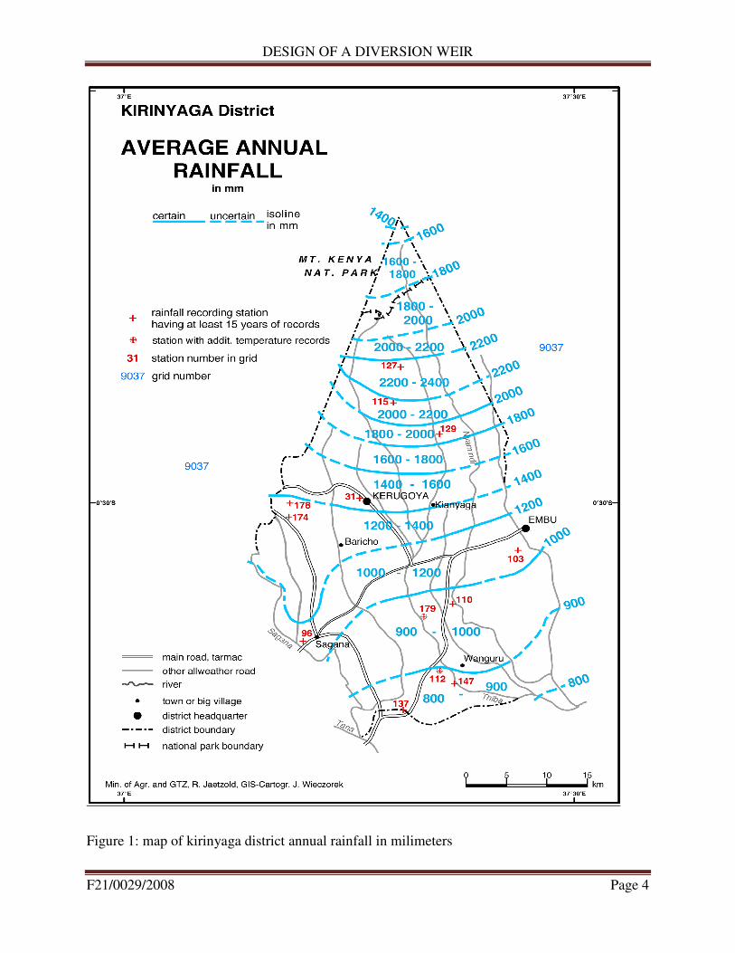
In addition, farmers will use the water for their domestic needs. Below is a map showing
Kirinyaga District/County Annual Rainfall in millimeters (mm).
DESIGN OF A DIVERSION WEIR
F21/0029/2008 Page 4
Figure 1: map of kirinyaga district annual rainfall in milimeters

DESIGN OF A DIVERSION WEIR
F21/0029/2008 Page 5
1.3 Problem Statement and Problem Analysis
Kirimara Irrigation Scheme is an irrigation scheme that is yet to be established inorder to help
farmers go on with their farming activities even when there is shortage of rains. I came to know
about this scheme and identified the problem that they were undergoing during my fieldwork
attachment at the Ministry of Water and Irrigation.
Due to the recent climate change, irrigation has become of importance to many farmers in most
places in Kenya.
Farmers have also gained interest in growing crops in and out of seasons whereby it has been a
great challenge since there are only two seasons of rainfall:- long rains that come from April to
May and short rains that come between the months of October to November. The residents of the
area therefore desperately need a water intake structure that will help supply water for their
irrigation activities as well as for their domestic use.
They also lack the skills to come up with an intake structure that will last for long, hence the
reason why I have decided to design for them an intake structure that will satisfy their needs. In
most cases, farmers use sacks filled with soil to divert water from a river. This kind of a structure
is not effective and in most cases will fail when the river swells, hence the need for a well
designed intake structure whose main consideration will be the design of a diversion weir.
1.4 Hypothesis
The designed diversion weir will help to raise and abstract water that will be enough to cater for
the needs of the farmers in Kirimara Irrigation Scheme.
The design will also help to cater for the present and future irrigation needs of the farmers, that
is, the 20% allowance put during the design will ensure that in future, farmers do not experience
water shortage when they increase in number.

DESIGN OF A DIVERSION WEIR
F21/0029/2008 Page 6
1.5. Objectives
1.5.1 Overall Objective
The overall objective of this project was to design a diversion weir for Kirimara Irrigation
Scheme.
1.5.2 Specific Objectives
The specific objectives were:-
• To identify the most suitable site for the diversion weir
• To determine water demand including crop water requirements and domestic uses
• To prepare detail design calculations and design drawings for the weir and the bill of
quantities.
1.6. Statement of scope
The design process will involve design calculations and preparation of the bill of quantities of
the materials to be used in the weir construction.
DESIGN OF A DIVERSION WEIR
F21/0029/2008
2.0 LITERATURE REVIEW
2.1 Introduction
Weir is a structure constructed at the head of canal, in order to divert the river water towards the
canal so as to ensure a regulated continuous supply of silt free water with certain minimum head
into the canal.
A weir can also be defined as a solid
divert water into a canal (low head structure).
The types of weir and its use depend upon the topography, geology, discharge, river morphology
etc. If the major part or the entire ponding of water
or nil part of it is achieved by the shutters then it is called weir.
Undersluice is the structure constructed side by the weir for the purpose of flushing t
silt by providing opening provided on
than the crest of the weir. It creates comparatively less turbulent pocket of water near intake.
The primary impact of a weir on the river, and indeed its primary function, is the raising
upstream water level above the natural level, as shown in the figure a below:
Figure
DESIGN OF A DIVERSION WEIR
Weir is a structure constructed at the head of canal, in order to divert the river water towards the
canal so as to ensure a regulated continuous supply of silt free water with certain minimum head
A weir can also be defined as a solid obstruction put across a river to raise its water level and
divert water into a canal (low head structure).
The types of weir and its use depend upon the topography, geology, discharge, river morphology
etc. If the major part or the entire ponding of water is achieved by a raised crest and smaller part
or nil part of it is achieved by the shutters then it is called weir.
Undersluice is the structure constructed side by the weir for the purpose of flushing t
pening provided on the weir portion with crest level positioned at lower level
than the crest of the weir. It creates comparatively less turbulent pocket of water near intake.
The primary impact of a weir on the river, and indeed its primary function, is the raising
r level above the natural level, as shown in the figure a below:
ure 2: Raising of water level by a Weir
Page 7
Weir is a structure constructed at the head of canal, in order to divert the river water towards the
canal so as to ensure a regulated continuous supply of silt free water with certain minimum head
obstruction put across a river to raise its water level and
The types of weir and its use depend upon the topography, geology, discharge, river morphology
is achieved by a raised crest and smaller part
Undersluice is the structure constructed side by the weir for the purpose of flushing the deposited
the weir portion with crest level positioned at lower level
than the crest of the weir. It creates comparatively less turbulent pocket of water near intake.
The primary impact of a weir on the river, and indeed its primary function, is the raising of

DESIGN OF A DIVERSION WEIR
F21/0029/2008 Page 8
For this reason, it is very possible to divert water from the main river and pipe it for use in
irrigation and domestic use.
2.2 Uses of Weirs
According to the (good practice manual by Charles Rickard, Rodney Day and Jeremy Purseglove
2003), weirs have been constructed and used in England for the following four fundamental
reasons:
2.2.1 Water Level Management
Most of the weirs in England and Wales have been constructed with the primary aim of water
level management. The impoundment of water is clearly a central function of weirs as by their
very nature they raise water levels relative to downstream conditions.
Increased water levels may be required to provide sufficient draft for navigation, to permit the
diversion or abstraction of water, or to provide a source of power. Many of the older weirs in
England and Wales were constructed in connection with water mills and navigation
improvements.
In cases where a river reach serves a navigation requirement, the increase in water levels is often
accompanied by the need for controllability of level to ensure that canal banks are not
overtopped, and that headroom under bridges is maintained.
This is often achieved by the construction of a weir with a long crest, such that water level
variation is small in response to changing flow conditions (the alternative is to have a gated weir
that will allow regulation of water level).
Side weirs are frequently used for water level management in navigable waterways
Weirs are also used to divert water into off-stream reservoirs or diversion channels, for flood
defense purposes or as part of a water supply scheme.
In providing raised water levels weirs may also be allowing the continued use of a reach of a
river for recreation and amenity.
DESIGN OF A DIVERSION WEIR
F21/0029/2008 Page 9
Weirs are also used to maintain groundwater levels.
2.2.2 Flow Measurement
Weirs also form the backbone of the national hydrometric system, which provides accurate
discharge information to facilitate development planning, flood forecasting, planning and
development of flood alleviation schemes, and water resources regulation.
Although any weir can be used to provide information on flow rates, weirs not specifically
designed with this in mind are likely to provide only approximate data.
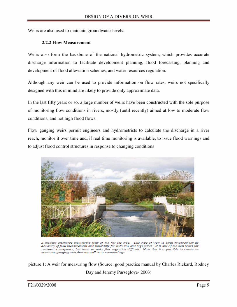
In the last fifty years or so, a large number of weirs have been constructed with the sole purpose
of monitoring flow conditions in rivers, mostly (until recently) aimed at low to moderate flow
conditions, and not high flood flows.
Flow gauging weirs permit engineers and hydrometrists to calculate the discharge in a river
reach, monitor it over time and, if real time monitoring is available, to issue flood warnings and
to adjust flood control structures in response to changing conditions
picture 1: A weir for measuring flow (Source: good practice manual by Charles Rickard, Rodney
Day and Jeremy Purseglove- 2003)

DESIGN OF A DIVERSION WEIR
F21/0029/2008 Page 10
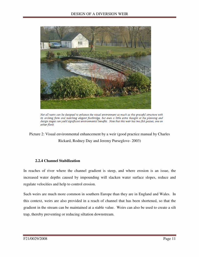
2.2.3 Environmental Enhancement
By raising water levels weirs may offer the opportunity to create wetland and conservation
habitats as well as enhance rivers and their surrounding areas.
However, the very fact that the weir creates a barrier in the river may be detrimental to nature
conservation, so it is important that all potential impacts are assessed before a decision is made.
Specific advantages of weirs include the prevention of the river channel drying out upstream of
the weir, and increased aeration of the river water as it cascades over the weir crest. These can
help to develop a rich and diverse environment for both aquatic and terrestrial species.
Weirs also open up options for improving low flow conditions by keeping water depths greater
than they otherwise would be, and providing opportunities for water meadows and landscaping.
As such, weirs may form an important component of a Water Level Management Plan (WLMP).
Weirs also have a significant impact on the amenity value of rivers, creating or enabling
opportunities for enhanced use of the river.
However, care needs to be exercised because the presence of a weir can constitute a barrier in the
watercourse thereby preventing the migration of fish upstream and downstream, thus limiting
their access to suitable spawning sites as well as reducing the overall biological value of a
fishery. Indeed, it can be argued that the ponded water upstream of a weir creates a more
homogeneous environment, with lower biodiversity than a natural river. Thus it is not
uncommon for weirs to be removed in order to return the channel to a more natural status.
DESIGN OF A DIVERSION WEIR
F21/0029/2008 Page 11
Picture 2: Visual environmental enhancement by a weir (good practice manual by Charles
Rickard, Rodney Day and Jeremy Purseglove- 2003)
2.2.4 Channel Stabilization
In reaches of river where the channel gradient is steep, and where erosion is an issue, the
increased water depths caused by impounding will slacken water surface slopes, reduce and
regulate velocities and help to control erosion.
Such weirs are much more common in southern Europe than they are in England and Wales. In
this context, weirs are also provided in a reach of channel that has been shortened, so that the
gradient in the stream can be maintained at a stable value. Weirs can also be used to create a silt
trap, thereby preventing or reducing siltation downstream.
DESIGN OF A DIVERSION WEIR
F21/0029/2008 Page 12
For such use it must be remembered that the effectiveness of the weir will depend on regular
removal of the trapped silt, and this will require safe and easy access to the weir for suitable
plant and equipment.
2.3 Types of Weirs
A weir with a sharp upstream corner or edge such that the water springs clear of the crest is
known as a sharp crested weir.
All the other weirs are classed as weirs not sharp crested.
Sharp crested weirs are classified according to the shape of the weir opening such as rectangular
weirs, triangular weirs or v-notch weirs, trapezoidal weirs and parabolic weirs.
Weirs not sharp crested are classified according to the shape of their cross-section, such as
broad-crested weirs, triangular weirs and trapezoidal weirs.
Sharp crested weirs are useful only as a means of measuring flowing water.
Weirs not sharp-crested are commonly incorporated into hydraulic structures as control or
regulation devices, with measurement of flow as their secondary function.
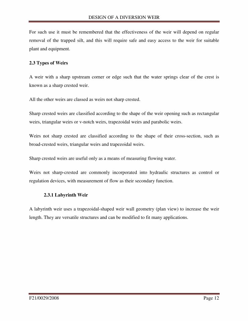
2.3.1 Labyrinth Weir
A labyrinth weir uses a trapezoidal-shaped weir wall geometry (plan view) to increase the weir
length. They are versatile structures and can be modified to fit many applications.
DESIGN OF A DIVERSION WEIR
F21/0029/2008 Page 13
Picture 3: Labyrinth weir (good practice manual by Charles Rickard, Rodney Day and Jeremy
Purseglove- 2003)
2.3.2 Broad-crested Weir
A broad-crested weir is a flat-crested structure, with a long crest compared to the flow thickness.
When the crest is "broad", the streamlines become parallel to the crest invert and the pressure
distribution above the crest is hydrostatic. The hydraulic characteristics of broad-crested weirs
were studied during the 19th and 20th centuries. Practical experience showed that the weir
overflow is affected by the upstream flow conditions and the weir.
2.3.3 Sharp Crested Weir (Fayoum Weir)
A sharp-crested weir allows the water to fall cleanly away from the weir. Sharp crested weirs are
typically 1/4" or thinner metal plates. Sharp crested weirs come in many different shapes such as
rectangular, V-notch and Cipolletti weirs. They are not very accurate or reliable especially when
reading and measuring from an orifice.

DESIGN OF A DIVERSION WEIR
F21/0029/2008 Page 14
2.3.4 Combination Weir
The sharp crested weirs can be considered into three groups according to the geometry of weir:
a) the rectangular weir,
b) the V or triangular notch and
c) special notches, such as trapezoidal, circular or parabolic weirs.
For accurate flow measurement over a wider range of flow rates, a combination weir combines a
V-notch weir with a rectangular weir. An example is manufactured by Thel-Mar Company and
has flow rates engraved along the side of the weir. This is typically used in pipes ranging from 4"
to 15" in diameter.
2.3.5 V-notch Weir
The V-notch weir is a triangular channel section, used to measure small discharge values. The
upper edge of the section is always above the water level, and so the channel is always triangular
simplifying calculation of the cross-sectional area. V-notch weirs are preferred for low
discharges as the head above the weir crest is more sensitive to changes in flow compared to
rectangular weirs.
2.3.6 Minimum Energy Loss Weir
The concept of the Minimum Energy Loss (MEL) structure was developed by Gordon McKay in
1971. The first MEL structure was the Redcliffe storm waterway system, also called Humpybong
Creek drainage outfall, completed in 1960 in the Redcliffe Peninsula in Queensland, Australia. It
consisted of a MEL weir acting as a streamlined drop inlet followed by a 137 m long culvert
discharging into the Pacific Ocean. The weir was designed to prevent beach sand being washed
in and choking the culvert, as well as to prevent salt intrusion in Humpybong Creek without
afflux. The structure is still in use and passed floods greater than the design flow in several
instances without flooding.

DESIGN OF A DIVERSION WEIR
F21/0029/2008 Page 15
The concept of the Minimum Energy Loss (MEL) weir was developed to pass large floods with
minimum energy loss and afflux, and nearly-constant total head along the waterway. The flow in
the approach channel is contracted through a streamlined chute and the channel width is
minimum at the chute toe, just before impinging into the downstream natural channel. The inlet
and chute are streamlined to avoid significant form losses and the flow may be critical from the
inlet lip to the chute toe at design flow. MEL weirs were designed specifically for situations
where the river catchment is characterized by torrential rain falls and by very small bed slope.
The first major MEL weir was the Clermont weir, if the small control weir at the entrance of
Redcliffe culvert is not counted. The largest, Chinchilla weir, is listed as a "large dam" by the
International Commission on Large Dams.
Figures b, c and d below show classification of weirs by shape:
Figure 3 : Rectangular Weir

DESIGN OF A DIVERSION WEIR
F21/0029/2008 Page 16
Figure 4 : Triangular Weir or V-notch
Figure 5: Trapezoidal Weir
DESIGN OF A DIVERSION WEIR
F21/0029/2008 Page 17
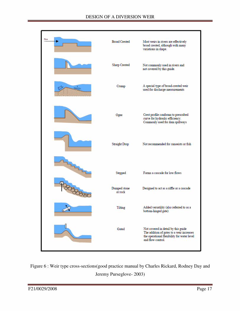
Figure 6 : Weir type cross-sections(good practice manual by Charles Rickard, Rodney Day and
Jeremy Purseglove- 2003)
DESIGN OF A DIVERSION WEIR
F21/0029/2008 Page 18
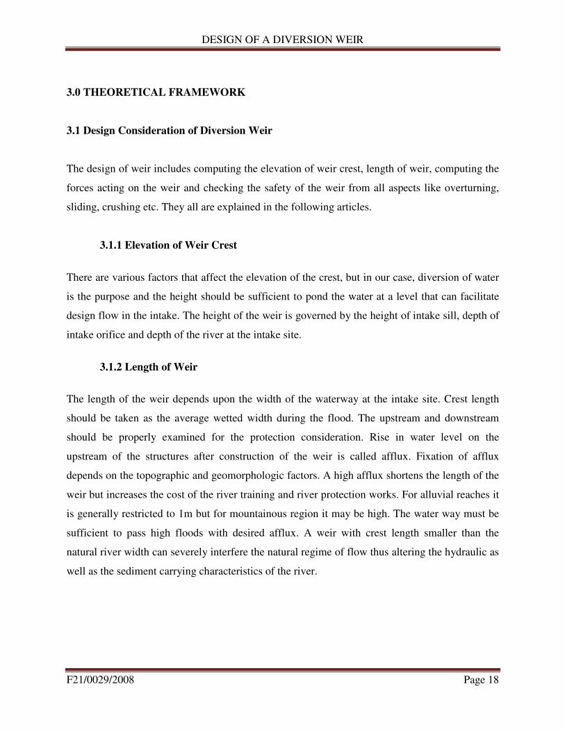
3.0 THEORETICAL FRAMEWORK
3.1 Design Consideration of Diversion Weir
The design of weir includes computing the elevation of weir crest, length of weir, computing the
forces acting on the weir and checking the safety of the weir from all aspects like overturning,
sliding, crushing etc. They all are explained in the following articles.
3.1.1 Elevation of Weir Crest
There are various factors that affect the elevation of the crest, but in our case, diversion of water
is the purpose and the height should be sufficient to pond the water at a level that can facilitate
design flow in the intake. The height of the weir is governed by the height of intake sill, depth of
intake orifice and depth of the river at the intake site.
3.1.2 Length of Weir
The length of the weir depends upon the width of the waterway at the intake site. Crest length
should be taken as the average wetted width during the flood. The upstream and downstream
should be properly examined for the protection consideration. Rise in water level on the
upstream of the structures after construction of the weir is called afflux. Fixation of afflux
depends on the topographic and geomorphologic factors. A high afflux shortens the length of the
weir but increases the cost of the river training and river protection works. For alluvial reaches it
is generally restricted to 1m but for mountainous region it may be high. The water way must be
sufficient to pass high floods with desired afflux. A weir with crest length smaller than the
natural river width can severely interfere the natural regime of flow thus altering the hydraulic as
well as the sediment carrying characteristics of the river.

DESIGN OF A DIVERSION WEIR
F21/0029/2008 Page 19
3.2 Forces acting on Weir
The main forces which are acting on the weir when it will be operation are: Water Pressure,
Uplift Pressure, Slit Pressure and Weight of the weir.
Figure 7 : Forces on the Weir
3.2.1 Water Pressure
It is the major external force acting on the weir. This is called hydrostatic pressure force and acts
perpendicular on the surface of the weir and its magnitude is given by:
P=0.5× γ× H2×b …………………………………………………………...……..……. (3.1)
Where, γ = Unit weight of water, H = Depth of water, b = Width of
The Weir surface. This pressure force acts on H/3 from the base.
H1
H2
V2 V3
H4
H3
U2 U1
Base
Base width
Water depth
above weir
Weir height
Crest width
V1

DESIGN OF A DIVERSION WEIR
F21/0029/2008 Page 20
3.2.2 Uplift Pressure
Water seeping through the pores, cracks and fissures of the foundation material, seeping through
the weir body itself and seepage from the bottom joint between the weir and its foundation exerts
an uplift pressure on the base of the weir. The uplift pressure virtually reduces the downward
weight of the weir hence acts against the dam stability. The analysis of seepage is done using
Khosla's Theory. Khosla's Theory is the mathematical solution of the Laplacian equation and it is
easy and accurate method for seepage analysis.
3.2.3 Silt Pressure
The silt gets deposited on the upstream of the weir and exerts the horizontal and vertical pressure
as exerted by the water. So, flushing of the silt should be done regularly to reduce its effect of
destabilizing the weir. It is done by the use of undersluice gate. The silt pressure is given by the
relation:
Psilt =0.5× γsub×H2×Ka …………………………………………………………..…… (3.2)
Where, γ sub=Submerged unit weight of silt; H= Depth of silt deposited and Ka= Coefficient of
Active earth pressure and is given by,
Ka=������
������ ………………………………………………………………………………(3.3)
where, �= Angle of internal friction of silt
The silt pressure force also acts at a height of H/3 from the base.
3.2.4 Weight of Weir
The weight of weir and its foundation is the major stabilizing/ resisting force. While calculating
the weight, the cross section is split into rectangle and triangle. The weight of each along with
their center of gravity is determined. The resultant of all these forces will represent the total

DESIGN OF A DIVERSION WEIR
F21/0029/2008 Page 21
weight of weir acting at the C.G. of weir. Simply, when the sectional area of each part is
multiplied by unit weight of concrete, weight of that part is obtained. The weir is designed with
ogee profile for spilling over its length. Hence weight is calculated by knowing its section and
multiplying by its unit weight.
3.3 Modes of Failure & Criteria for Structural Stability of Weir
3.3.1 Overturning about the toe
If resultant of all the forces acting in the weir passes outside, the weir shall rotate and overturn
about the toe. Practically, this condition will not arise because the weir will fail much earlier by
compression. The ratio of resisting moment to the overturning moment about the toe is the factor
of safety against overturning and it should greater than1.5 for safety.
3.3.2 Compression or Crushing
While designing the weir section it should be so design that the resultant should pass through
middle 3 rd
part of the section to avoid the possible tension on the weir section. The section
should be totally in compression. So, weir should be checked against the failure by crushing of
its material. If the actual compressive stress may exceed the allowable stress, the structure
material may get crushed. The vertical combine stress at the base is given by
Min/max=∑�
[1±6×
�
] ……………………………………………………………………….(3.4)
Where e =
�-x, x=
∑�
∑�,e = eccentricity of the resultant force from the centre of the base.
3.3.3 Sliding
Sliding will occur when the net horizontal force above any plane in the weir or at the base of the
weir exceed the frictional resistance developed at that level. Factor of safety against the sliding is
measured as Shear Stability Factor (SSF) and is given by:
DESIGN OF A DIVERSION WEIR
F21/0029/2008 Page 22
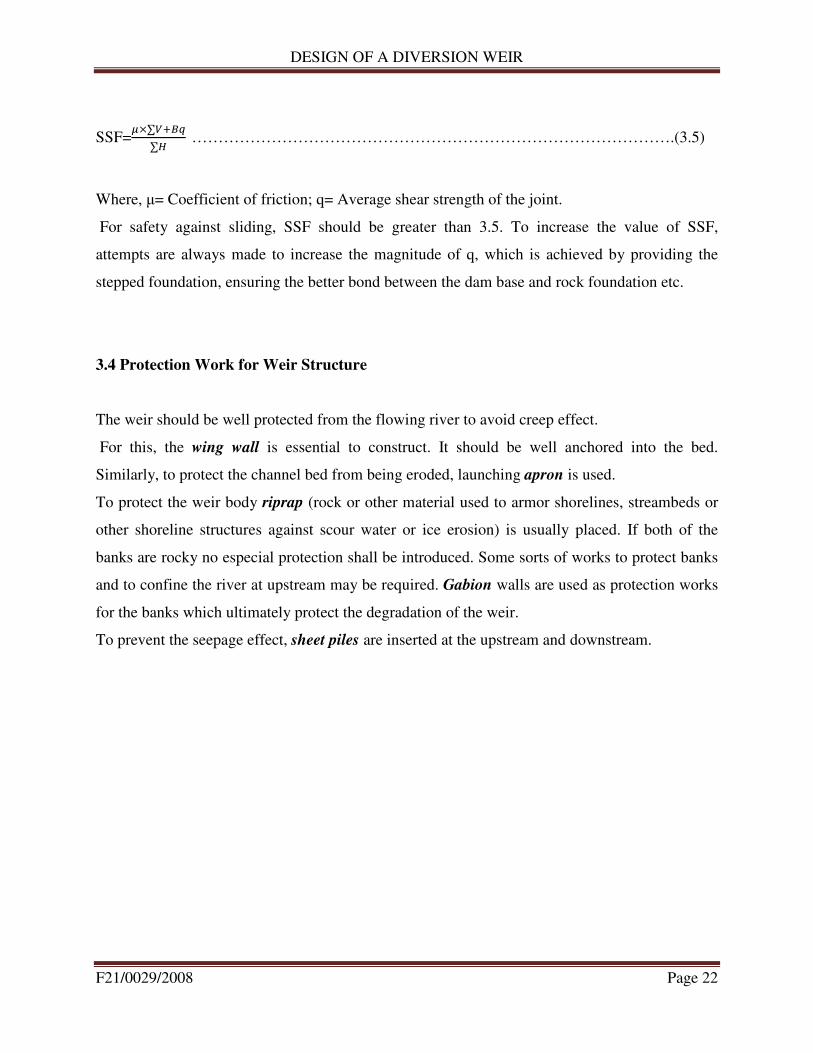
SSF=�×∑�� �
∑� ……………………………………………………………………………….(3.5)
Where, µ= Coefficient of friction; q= Average shear strength of the joint.
For safety against sliding, SSF should be greater than 3.5. To increase the value of SSF,
attempts are always made to increase the magnitude of q, which is achieved by providing the
stepped foundation, ensuring the better bond between the dam base and rock foundation etc.
3.4 Protection Work for Weir Structure
The weir should be well protected from the flowing river to avoid creep effect.
For this, the wing wall is essential to construct. It should be well anchored into the bed.
Similarly, to protect the channel bed from being eroded, launching apron is used.
To protect the weir body riprap (rock or other material used to armor shorelines, streambeds or
other shoreline structures against scour water or ice erosion) is usually placed. If both of the
banks are rocky no especial protection shall be introduced. Some sorts of works to protect banks
and to confine the river at upstream may be required. Gabion walls are used as protection works
for the banks which ultimately protect the degradation of the weir.
To prevent the seepage effect, sheet piles are inserted at the upstream and downstream.
DESIGN OF A DIVERSION WEIR
F21/0029/2008 Page 23
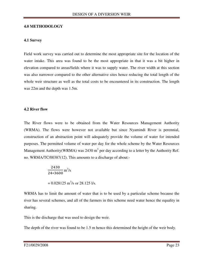
4.0 METHODOLOGY
4.1 Survey
Field work survey was carried out to determine the most appropriate site for the location of the
water intake. This area was found to be the most appropriate in that it was a bit higher in
elevation compared to areas/fields where it was to supply water. The river width at this section
was also narrower compared to the other alternative sites hence reducing the total length of the
whole weir structure as well as the total costs to be encountered in its construction. The length
was 22m and the depth was 1.5m.
4.2 River flow
The River flows were to be obtained from the Water Resources Management Authority
(WRMA). The flows were however not available but since Nyamindi River is perennial,
construction of an abstraction point will adequately provide the volume of water for intended
purposes. The permitted volume of water per day for the whole scheme by the Water Resources
Management Authority(WRMA) was 2430 m3 per day according to a letter by the Authority Ref.
no. WRMA/TC/00387(12). This amounts to a discharge of about:-
����
��∗���� m
3/s
= 0.028125 m3/s or 28.125 l/s.
WRMA has to limit the amount of water that is to be used by a particular scheme because the
river has several schemes, and all of the farmers in this scheme need water hence the equality in
sharing.
This is the discharge that was used to design the weir.
The depth of the river was found to be 1.5 m hence this determined the height of the weir body.
DESIGN OF A DIVERSION WEIR
F21/0029/2008 Page 24
4.3 Water Demand
4.3.1 Crop Water Requirement
Introduction
The scheme water requirement is the total amount of water that will be supplied for effective
scheduled irrigation. The following primary assumptions have been made in the determination of
the scheme water requirements:
• The potential Evapotranspiration is maximum
• The irrigated area is 100% of the effective irrigation area of the scheme as agreed by the
members
• The crop is at its peak growth
• The amount of soil water storage is negligible
Crop Water Requirement
The following factors / parameters were considered during the review of the general water
requirements:
• Crops and cropping patterns;
• Crop factors (Kc);
• Evapotranspiration and effective rainfall;
• Irrigation efficiencies (for sprinkler irrigation system);
• Irrigation hours per day and no. of settings per day;
• Irrigation days per week;
• Irrigation area.
• ETcrop =ETo x Kc
Where;
ETo =Evapo-transpiration, which is given by; Evaporation from free water surface x
adjustment factor (0.75 for highlands above 1100 m.a.s.l and 0.8 for hot and dry low
areas below 1100 m.a.s.l)
Kc Crop Coefficient taken as 0.9 for most crops

DESIGN OF A DIVERSION WEIR
F21/0029/2008 Page 25
Crops
Various crops have been proposed to be produced under irrigation, which include:
• Onions
• Bananas
• Watermelons
• French beans
• Tomatoes
A cropping pattern that ensured all the crops were grown was used.
Reference Crop Evapotranspiration, ETo
values used are those that were obtained from CLIMWAT/CROPWAT softwares and are as
given in table 1 below:-
Table 1: reference crop evapotranspiration
Month
Min
Temp
Max
Temp Humidity Wind Sun Rad ETo
°C °C % km/day hours MJ/m²/day mm/day
January 11 33 68 112 8.9 22.6 4.85
February 11.7 35 60 121 9 23.4 5.39
March 12.1 36.2 62 130 8.1 22.2 5.45
April 11.6 34.8 72 104 6.6 19.2 4.5
May 11.2 33.6 74 78 6.5 18 3.96
June 10.5 31.7 72 69 4.6 14.7 3.27
July 10.2 30.6 70 78 4 14.1 3.17
August 10.3 31 67 104 4.3 15.3 3.6
September 11.2 33.6 62 138 6 18.6 4.65
October 11.7 35.2 61 147 7.5 21 5.31
November 11.1 33.3 75 104 6.6 19.2 4.32
December 10.9 32.7 74 112 7.3 19.9 4.37
Average 11.1 33.4 68 108 6.6 19 4.4
DESIGN OF A DIVERSION WEIR
F21/0029/2008 Page 26
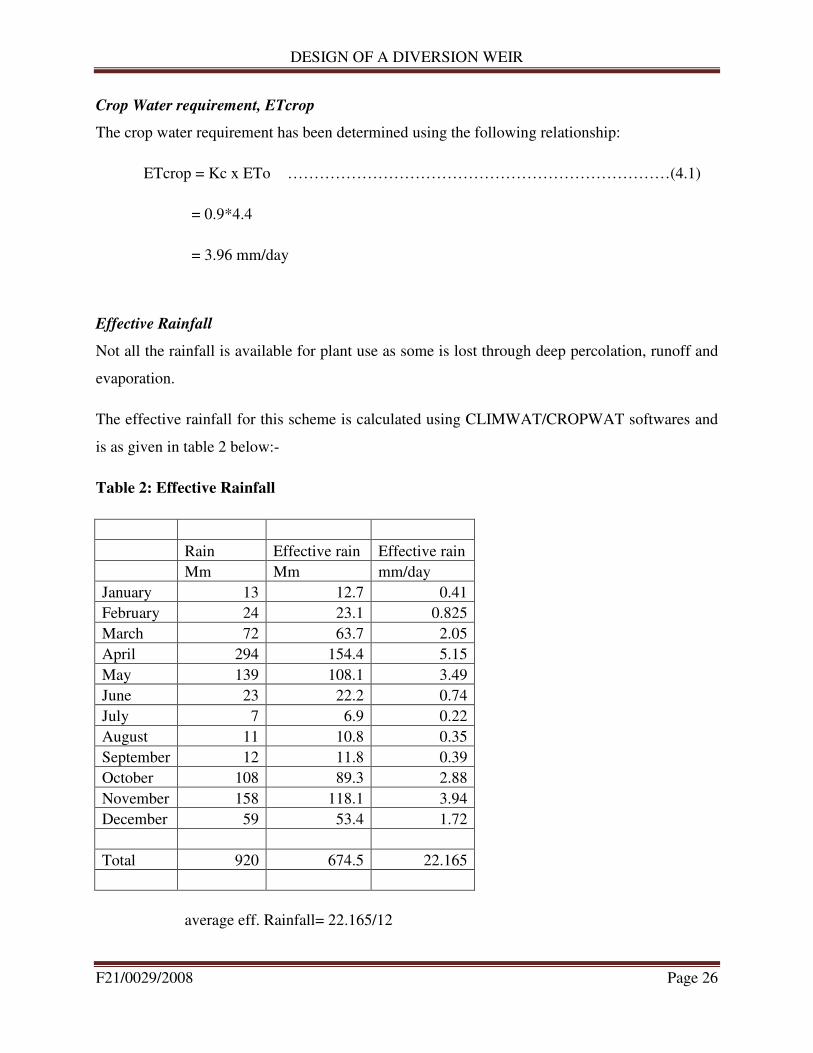
Crop Water requirement, ETcrop
The crop water requirement has been determined using the following relationship:
ETcrop = Kc x ETo ………………………………………………………………(4.1)
= 0.9*4.4
= 3.96 mm/day
Effective Rainfall
Not all the rainfall is available for plant use as some is lost through deep percolation, runoff and
evaporation.
The effective rainfall for this scheme is calculated using CLIMWAT/CROPWAT softwares and
is as given in table 2 below:-
Table 2: Effective Rainfall
Rain Effective rain Effective rain
Mm Mm mm/day
January 13 12.7 0.41
February 24 23.1 0.825
March 72 63.7 2.05
April 294 154.4 5.15
May 139 108.1 3.49
June 23 22.2 0.74
July 7 6.9 0.22
August 11 10.8 0.35
September 12 11.8 0.39
October 108 89.3 2.88
November 158 118.1 3.94
December 59 53.4 1.72
Total 920 674.5 22.165
average eff. Rainfall= 22.165/12
DESIGN OF A DIVERSION WEIR
F21/0029/2008 Page 27
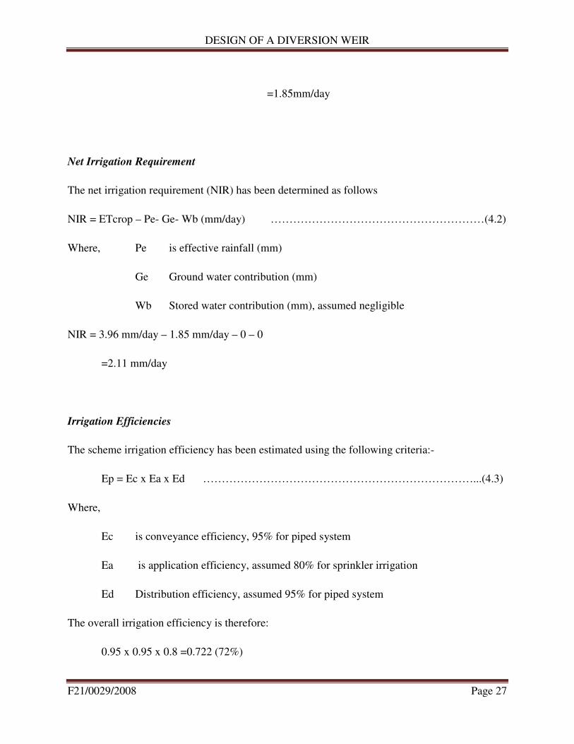
=1.85mm/day
Net Irrigation Requirement
The net irrigation requirement (NIR) has been determined as follows
NIR = ETcrop – Pe- Ge- Wb (mm/day) …………………………………………………(4.2)
Where, Pe is effective rainfall (mm)
Ge Ground water contribution (mm)
Wb Stored water contribution (mm), assumed negligible
NIR = 3.96 mm/day – 1.85 mm/day – 0 – 0
=2.11 mm/day
Irrigation Efficiencies
The scheme irrigation efficiency has been estimated using the following criteria:-
Ep = Ec x Ea x Ed ………………………………………………………………...(4.3)
Where,
Ec is conveyance efficiency, 95% for piped system
Ea is application efficiency, assumed 80% for sprinkler irrigation
Ed Distribution efficiency, assumed 95% for piped system
The overall irrigation efficiency is therefore:
0.95 x 0.95 x 0.8 =0.722 (72%)
DESIGN OF A DIVERSION WEIR
F21/0029/2008 Page 28
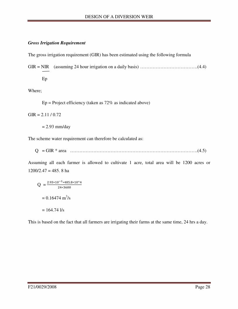
Gross Irrigation Requirement
The gross irrigation requirement (GIR) has been estimated using the following formula
GIR = NIR (assuming 24 hour irrigation on a daily basis) ……………………………….(4.4)
Ep
Where;
Ep = Project efficiency (taken as 72% as indicated above)
GIR = 2.11 / 0.72
= 2.93 mm/day
The scheme water requirement can therefore be calculated as:
Q = GIR * area ……………………………………………………………………….(4.5)
Assuming all each farmer is allowed to cultivate 1 acre, total area will be 1200 acres or
1200/2.47 = 485. 8 ha
Q = �.��∗����∗���.�∗��^�
��∗����
= 0.16474 m3/s
= 164.74 l/s
This is based on the fact that all farmers are irrigating their farms at the same time, 24 hrs a day.
DESIGN OF A DIVERSION WEIR
F21/0029/2008 Page 29
4.3.2 Domestic Use
The scheme is being designed to cater for 1,200 farmers and each of these farmers will be
allowed to cultivate 1 acre piece of land.
Each farm has approximately six family members. Assuming that each of these members uses 25
l/day, the total amount of water used by all the farmer per second amounts to:-
1200*6*��
��∗���� = 2.08 l/s
Total amount of water for the scheme is 167.74l/s + 2.08l/s
= 169.82l/s

DESIGN OF A DIVERSION WEIR
F21/0029/2008 Page 30
5.0 DETAILED DESIGN OF THE INTAKE WORKS
5.1 Introduction
The proposed weir is 22.0 m long and 1.5 m above the river bed. The main weir body and
retaining walls are all to be founded on rock and are proposed to be made of reinforced concrete
to avoid any shear failure.
The stability analysis for both the weir and the retaining wing walls has been carried out and
necessary reinforcement provided while applying a factor safety of 1.5.
The weir site has been provided with protection measures both on the upstream and downstream
sides. Protection measures include grouted riprap and tipped apron on the river bed and stone
pitching on the river side slopes.
A freeboard of 0.5m m has been added to the retaining wing walls above the weir crest. This has
been found to be adequate contain flood flows of up to 20-year return period.
Scouring pipe sluices have been provided within the weir body for continuous silt removal and a
sluice gate provided to help in flushing the intake after every major flood event.
Complete drawings of the weir plan as well as the specified sections are drawn into scale and
provided separately as the plan of the intake and the respective sections as shown in the plan.
DESIGN OF A DIVERSION WEIR
F21/0029/2008 Page 31
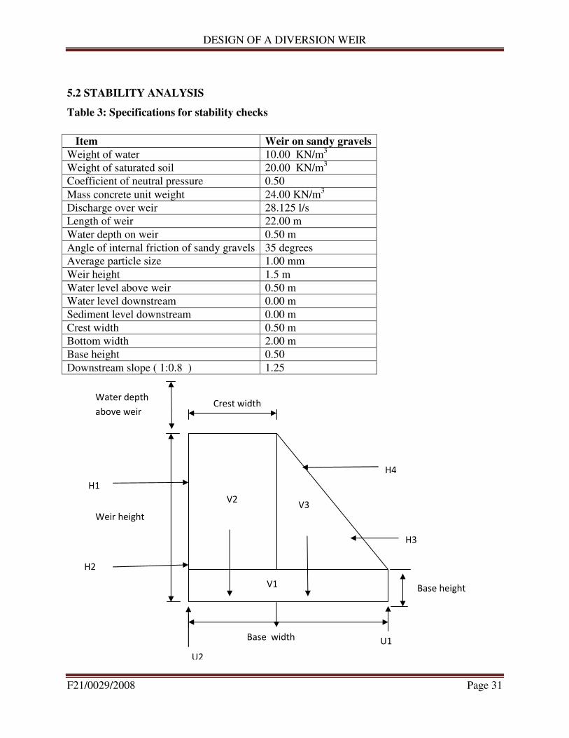
5.2 STABILITY ANALYSIS
Table 3: Specifications for stability checks
Item Weir on sandy gravels
Weight of water 10.00 KN/m3
Weight of saturated soil 20.00 KN/m3
Coefficient of neutral pressure 0.50
Mass concrete unit weight 24.00 KN/m3
Discharge over weir 28.125 l/s
Length of weir 22.00 m
Water depth on weir 0.50 m
Angle of internal friction of sandy gravels 35 degrees
Average particle size 1.00 mm
Weir height 1.5 m
Water level above weir 0.50 m
Water level downstream 0.00 m
Sediment level downstream 0.00 m
Crest width 0.50 m
Bottom width 2.00 m
Base height 0.50
Downstream slope ( 1:0.8 ) 1.25
Crest width Water depth
above weir
H4
H3
Base height
V3 V2
H1
H2
Weir height
Base width U1
U2
V1
DESIGN OF A DIVERSION WEIR
F21/0029/2008 Page 32
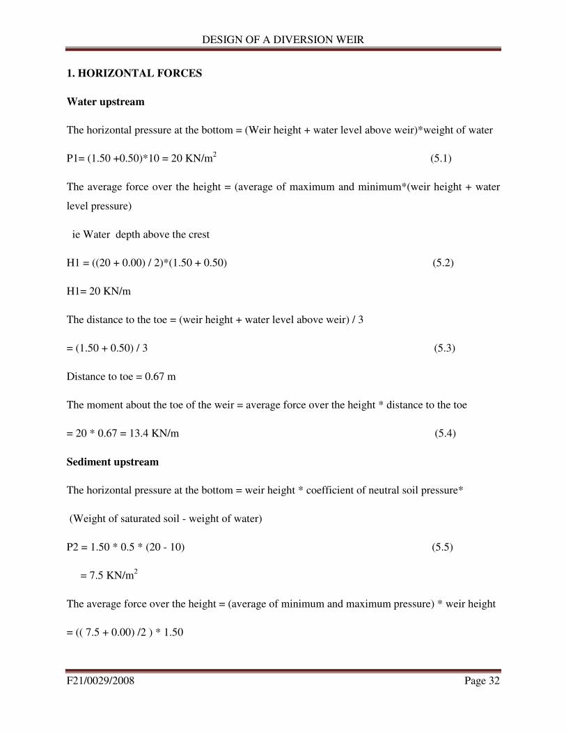
1. HORIZONTAL FORCES
Water upstream
The horizontal pressure at the bottom = (Weir height + water level above weir)*weight of water
P1= (1.50 +0.50)*10 = 20 KN/m2 (5.1)
The average force over the height = (average of maximum and minimum*(weir height + water
level pressure)
ie Water depth above the crest
H1 = ((20 + 0.00) / 2)*(1.50 + 0.50) (5.2)
H1= 20 KN/m
The distance to the toe = (weir height + water level above weir) / 3
= (1.50 + 0.50) / 3 (5.3)
Distance to toe = 0.67 m
The moment about the toe of the weir = average force over the height * distance to the toe
= 20 * 0.67 = 13.4 KN/m (5.4)
Sediment upstream
The horizontal pressure at the bottom = weir height * coefficient of neutral soil pressure*
(Weight of saturated soil - weight of water)
P2 = 1.50 * 0.5 * (20 - 10) (5.5)
= 7.5 KN/m2
The average force over the height = (average of minimum and maximum pressure) * weir height
= (( 7.5 + 0.00) /2 ) * 1.50
DESIGN OF A DIVERSION WEIR
F21/0029/2008 Page 33
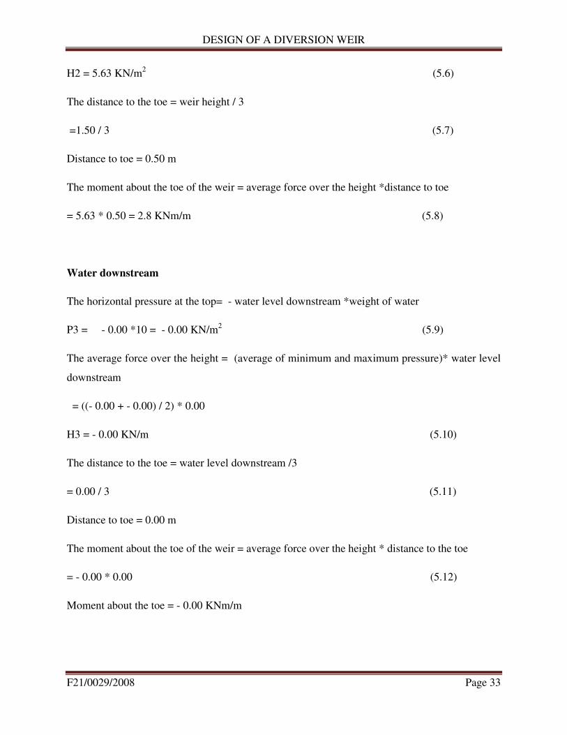
H2 = 5.63 KN/m2 (5.6)
The distance to the toe = weir height / 3
=1.50 / 3 (5.7)
Distance to toe = 0.50 m
The moment about the toe of the weir = average force over the height *distance to toe
= 5.63 * 0.50 = 2.8 KNm/m (5.8)
Water downstream
The horizontal pressure at the top= - water level downstream *weight of water
P3 = - 0.00 *10 = - 0.00 KN/m2 (5.9)
The average force over the height = (average of minimum and maximum pressure)* water level
downstream
= ((- 0.00 + - 0.00) / 2) * 0.00
H3 = - 0.00 KN/m (5.10)
The distance to the toe = water level downstream /3
= 0.00 / 3 (5.11)
Distance to toe = 0.00 m
The moment about the toe of the weir = average force over the height * distance to the toe
= - 0.00 * 0.00 (5.12)
Moment about the toe = - 0.00 KNm/m
DESIGN OF A DIVERSION WEIR
F21/0029/2008 Page 34
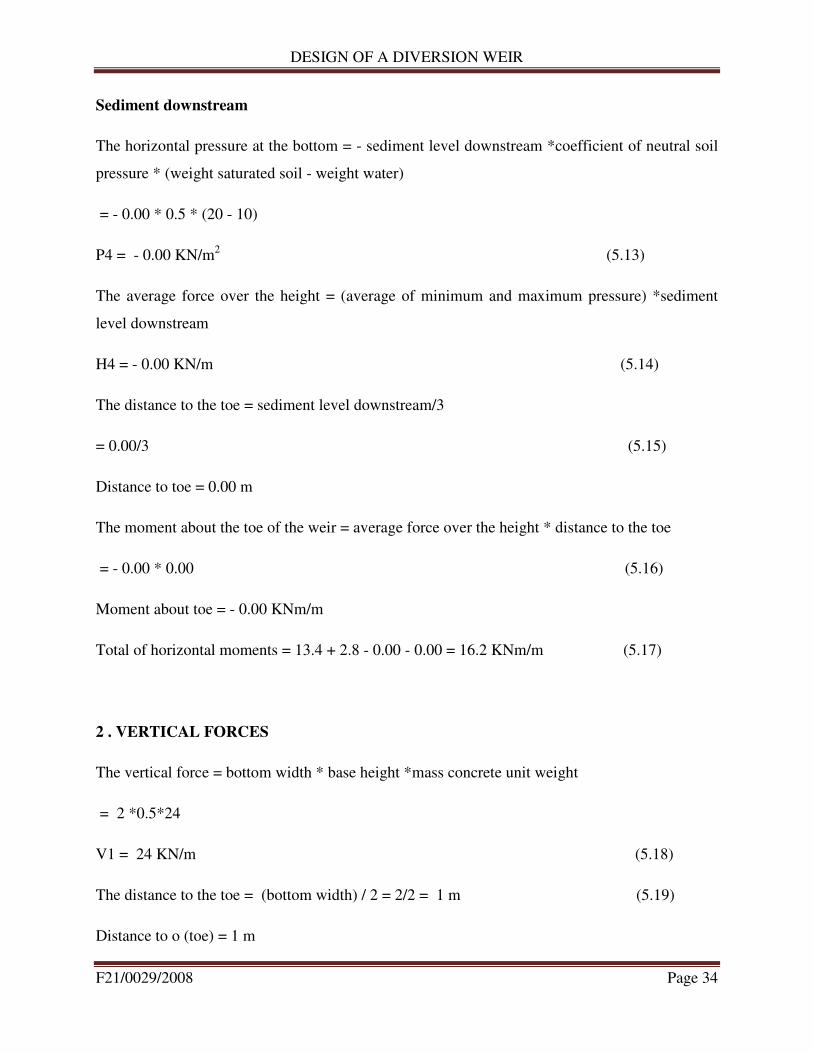
Sediment downstream
The horizontal pressure at the bottom = - sediment level downstream *coefficient of neutral soil
pressure * (weight saturated soil - weight water)
= - 0.00 * 0.5 * (20 - 10)
P4 = - 0.00 KN/m2
(5.13)
The average force over the height = (average of minimum and maximum pressure) *sediment
level downstream
H4 = - 0.00 KN/m (5.14)
The distance to the toe = sediment level downstream/3
= 0.00/3 (5.15)
Distance to toe = 0.00 m
The moment about the toe of the weir = average force over the height * distance to the toe
= - 0.00 * 0.00 (5.16)
Moment about toe = - 0.00 KNm/m
Total of horizontal moments = 13.4 + 2.8 - 0.00 - 0.00 = 16.2 KNm/m (5.17)
2 . VERTICAL FORCES
The vertical force = bottom width * base height *mass concrete unit weight
= 2 *0.5*24
V1 = 24 KN/m (5.18)
The distance to the toe = (bottom width) / 2 = 2/2 = 1 m (5.19)
Distance to o (toe) = 1 m
DESIGN OF A DIVERSION WEIR
F21/0029/2008 Page 35
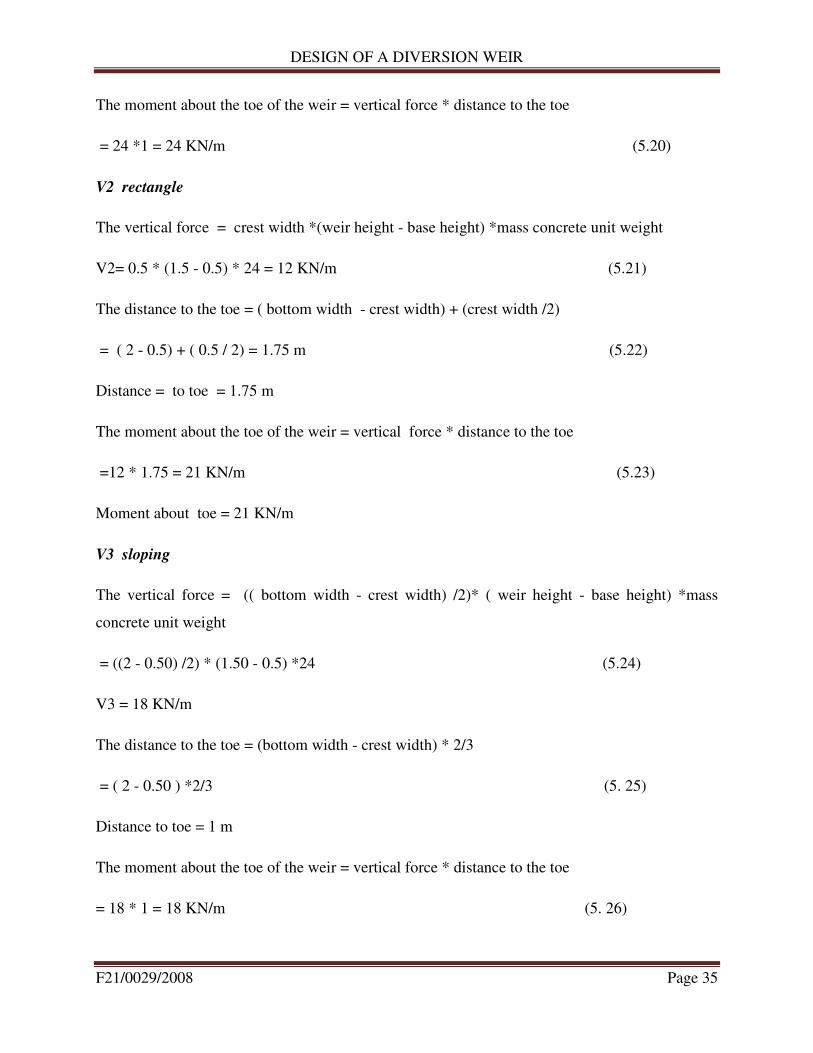
The moment about the toe of the weir = vertical force * distance to the toe
= 24 *1 = 24 KN/m (5.20)
V2 rectangle
The vertical force = crest width *(weir height - base height) *mass concrete unit weight
V2= 0.5 * (1.5 - 0.5) * 24 = 12 KN/m (5.21)
The distance to the toe = ( bottom width - crest width) + (crest width /2)
= ( 2 - 0.5) + ( 0.5 / 2) = 1.75 m (5.22)
Distance = to toe = 1.75 m
The moment about the toe of the weir = vertical force * distance to the toe
=12 * 1.75 = 21 KN/m (5.23)
Moment about toe = 21 KN/m
V3 sloping
The vertical force = (( bottom width - crest width) /2)* ( weir height - base height) *mass
concrete unit weight
= ((2 - 0.50) /2) * (1.50 - 0.5) *24 (5.24)
V3 = 18 KN/m
The distance to the toe = (bottom width - crest width) * 2/3
= ( 2 - 0.50 ) *2/3 (5. 25)
Distance to toe = 1 m
The moment about the toe of the weir = vertical force * distance to the toe
= 18 * 1 = 18 KN/m (5. 26)
DESIGN OF A DIVERSION WEIR
F21/0029/2008 Page 36
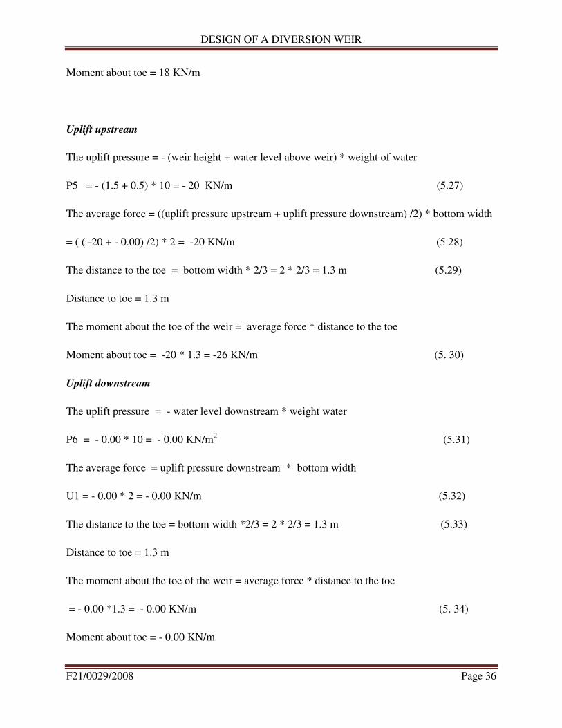
Moment about toe = 18 KN/m
Uplift upstream
The uplift pressure = - (weir height + water level above weir) * weight of water
P5 = - (1.5 + 0.5) * 10 = - 20 KN/m (5.27)
The average force = ((uplift pressure upstream + uplift pressure downstream) /2) * bottom width
= ( ( -20 + - 0.00) /2) * 2 = -20 KN/m (5.28)
The distance to the toe = bottom width * 2/3 = 2 * 2/3 = 1.3 m (5.29)
Distance to toe = 1.3 m
The moment about the toe of the weir = average force * distance to the toe
Moment about toe = -20 * 1.3 = -26 KN/m (5. 30)
Uplift downstream
The uplift pressure = - water level downstream * weight water
P6 = - 0.00 * 10 = - 0.00 KN/m2 (5.31)
The average force = uplift pressure downstream * bottom width
U1 = - 0.00 * 2 = - 0.00 KN/m (5.32)
The distance to the toe = bottom width *2/3 = 2 * 2/3 = 1.3 m (5.33)
Distance to toe = 1.3 m
The moment about the toe of the weir = average force * distance to the toe
= - 0.00 *1.3 = - 0.00 KN/m (5. 34)
Moment about toe = - 0.00 KN/m
DESIGN OF A DIVERSION WEIR
F21/0029/2008 Page 37
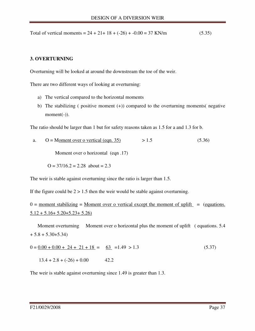
Total of vertical moments = 24 + 21+ 18 + (-26) + -0.00 = 37 KN/m (5.35)
3. OVERTURNING
Overturning will be looked at around the downstream the toe of the weir.
There are two different ways of looking at overturning:
a) The vertical compared to the horizontal moments
b) The stabilizing ( positive moment (+)) compared to the overturning moments( negative
moment(-)).
The ratio should be larger than 1 but for safety reasons taken as 1.5 for a and 1.3 for b.
a. O = Moment over o vertical (eqn. 35) > 1.5 (5.36)
Moment over o horizontal (eqn .17)
O = 37/16.2 = 2.28 about = 2.3
The weir is stable against overturning since the ratio is larger than 1.5.
If the figure could be 2 > 1.5 then the weir would be stable against overturning.
0 = moment stabilizing = Moment over o vertical except the moment of uplift = (equations.
5.12 + 5.16+ 5.20+5.23+ 5.26)
Moment overturning Moment over o horizontal plus the moment of uplift ( equations. 5.4
+ 5.8 + 5.30+5.34)
0 = 0.00 + 0.00 + 24 + 21 + 18 = 63 =1.49 > 1.3 (5.37)
13.4 + 2.8 + (-26) + 0.00 42.2
The weir is stable against overturning since 1.49 is greater than 1.3.
DESIGN OF A DIVERSION WEIR
F21/0029/2008 Page 38
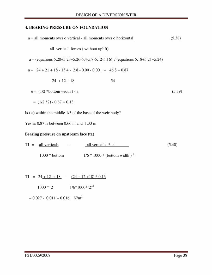
4. BEARING PRESSURE ON FOUNDATION
a = all moments over o vertical - all moments over o horizontal (5.38)
all vertical forces ( without uplift)
a = (equations 5.20+5.23+5.26-5.4-5.8-5.12-5.16) / (equations 5.18+5.21+5.24)
a = 24 + 21 + 18 - 13.4 - 2.8 - 0.00 - 0.00 = 46.8 = 0.87
24 + 12 + 18 54
e = (1/2 *bottom width ) - a (5.39)
= (1/2 *2) - 0.87 = 0.13
Is ( a) within the middle 1/3 of the base of the weir body?
Yes as 0.87 is between 0.66 m and 1.33 m
Bearing pressure on upstream face (t1)
T1 = all verticals - all verticals * e (5.40)
1000 * bottom 1/6 * 1000 * (bottom width ) 2
T1 = 24 + 12 + 18 - (24 + 12 +18) * 0.13
1000 * 2 1/6*1000*(2)2
= 0.027 - 0.011 = 0.016 N/m2
DESIGN OF A DIVERSION WEIR
F21/0029/2008 Page 39
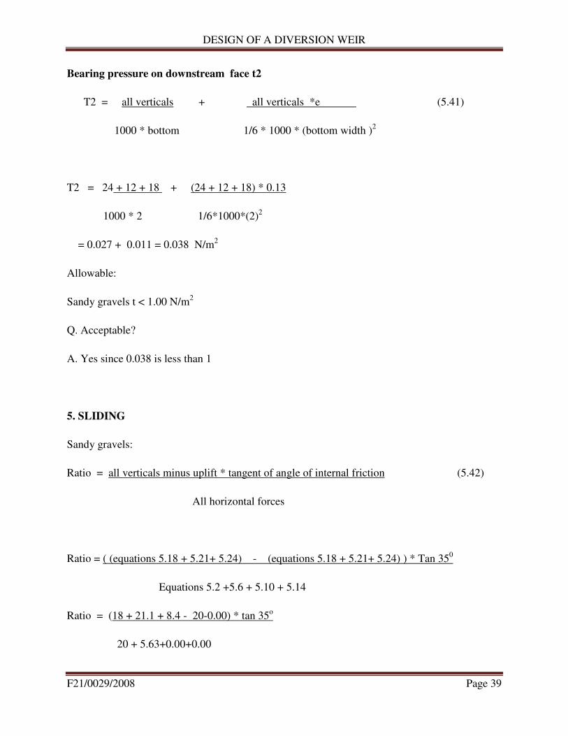
Bearing pressure on downstream face t2
T2 = all verticals + all verticals *e (5.41)
1000 * bottom 1/6 * 1000 * (bottom width )2
T2 = 24 + 12 + 18 + (24 + 12 + 18) * 0.13
1000 * 2 1/6*1000*(2)2
= 0.027 + 0.011 = 0.038 N/m2
Allowable:
Sandy gravels t < 1.00 N/m2
Q. Acceptable?
A. Yes since 0.038 is less than 1
5. SLIDING
Sandy gravels:
Ratio = all verticals minus uplift * tangent of angle of internal friction (5.42)
All horizontal forces
Ratio = ( (equations 5.18 + 5.21+ 5.24) - (equations 5.18 + 5.21+ 5.24) ) * Tan 350
Equations 5.2 +5.6 + 5.10 + 5.14
Ratio = (18 + 21.1 + 8.4 - 20-0.00) * tan 35o
20 + 5.63+0.00+0.00

DESIGN OF A DIVERSION WEIR
F21/0029/2008 Page 40
= 19.2/25.6 = 0.75
Allowable : sandy gravels ratio > 1.3
Q . Acceptable?
A. No.
The weir is not safe against sliding effect hence a key is required
Method 2
Sandy gravels
Ratio = All horizontal forces (5.43)
All verticals forces minus uplift
Ratio = equations 5.2 +5.6+5.10+5.14
equations 5.18+5.21+5.24-5.28-5.32
Ratio = 20+5.03+ 0.00+0.00 = 25 = 0.73
24+12+18-20-0.00 34
Allowable : Sandy gravels/coarse sand ratio < 0.4
Q. acceptable?
A. No
As the weir is not safe against the sliding effect a key trench is required since the ratio is greater
than 0.73.
Horizontal force (F) in key trench is:

DESIGN OF A DIVERSION WEIR
F21/0029/2008 Page 41
F= ( all vertical minus uplift forces ) * ratio - all horizontal forces (5.44)
F = (24+12+18-20-0.00) * 0.4 - (20+5.03+ 0.00+0.00 ) = 13.6 -25.0 = - 11.4 KN/m
The key trench width (W) should be:
Permissible shear stress (q) in key ( mass concrete mix 1:2:4) is 0.25 N/m2
q = ( required horizontal force) * load factor (5.45)
1000 * required trench width
0.25 = ( 11.4 * 103
) * 1.7
1000 * w
The load factor is a safety factor taken for the impact of forces. It is taken as 1.7
W = 77.52 mm = 0.08 m
The key trench depth (D) will be
F= 1/2 * T permissible compressive stress * D*1000
11.4 * 103
= 1/2 * 0.25 * D*1000
D= 91.2 mm = 0.091 m
(Gravel : horizontal compressive stress = 0.25 N/mm2)
(Sand : horizontal compressive stress = 0.10 N/mm2)
It can be concluded that only a small key is required to overcome the sliding tendency

DESIGN OF A DIVERSION WEIR
F21/0029/2008 Page 42
6. STRESSES IN CONCRETE
Load factor = 1.7
A. compression
t = ( all vertical forces-uplift forces + all verticals - uplift forces *e) * load factor (5.46)
1000 * bottom width 1/6 *1000 *(bottom width)^2
t = (24+12+18-20-0.00 + (24+12+18- 20-0.00) * 0.13 ))* 1.7
1000 * 2 1/6 *1000 *(2) 2
t = ( 34 + 4.42) * 1.7 = (0.017 + 0.066) * 1.7 = 0.14 N/m2
1000 * 2 1/6 *1000 *(2) 2
B. Tensile
t = ( all vertical forces-uplift forces - all verticals - uplift forces *e) * load factor (5.47)
1000 * bottom width 1/6 *1000 *(bottom width)^2
t = (24+12+18-20-0.00 - (24+12+18- 20-0.00) * 0.13 ))* 1.7
1000 * 2 1/6 *1000 *(2) 2
t = ( 34 - 4.42) * 1.7 = (0.017 - 0.066) * 1.7 = - 0.083 N/m2
1000 * 2 1/6 *1000 *(2) 2
Nominal mix 1 : 2 : 3 permissible is 1.00 N/m2 so tensile stress is within limit
Nominal mix 1 : 2 : 4 permissible is 0.50 N/m2 so tensile stress is within limit
Nominal mix 1 : 2.5 : 5 permissible is 0.35 N/m2 so tensile stress is within limit
DESIGN OF A DIVERSION WEIR
F21/0029/2008 Page 43
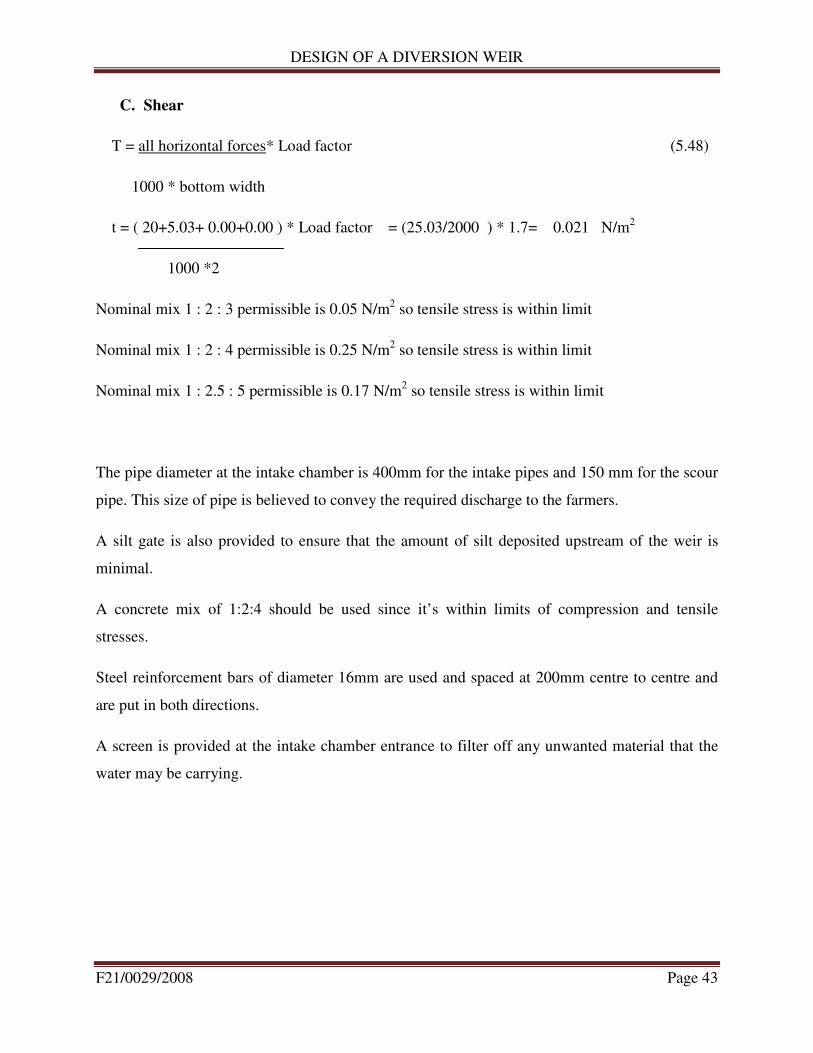
C. Shear
T = all horizontal forces* Load factor (5.48)
1000 * bottom width
t = ( 20+5.03+ 0.00+0.00 ) * Load factor = (25.03/2000 ) * 1.7= 0.021 N/m2
1000 *2
Nominal mix 1 : 2 : 3 permissible is 0.05 N/m2 so tensile stress is within limit
Nominal mix 1 : 2 : 4 permissible is 0.25 N/m2 so tensile stress is within limit
Nominal mix 1 : 2.5 : 5 permissible is 0.17 N/m2 so tensile stress is within limit
The pipe diameter at the intake chamber is 400mm for the intake pipes and 150 mm for the scour
pipe. This size of pipe is believed to convey the required discharge to the farmers.
A silt gate is also provided to ensure that the amount of silt deposited upstream of the weir is
minimal.
A concrete mix of 1:2:4 should be used since it’s within limits of compression and tensile
stresses.
Steel reinforcement bars of diameter 16mm are used and spaced at 200mm centre to centre and
are put in both directions.
A screen is provided at the intake chamber entrance to filter off any unwanted material that the
water may be carrying.

DESIGN OF A DIVERSION WEIR
F21/0029/2008 Page 44
5.3 BILL OF QUANTITIES
Volume of the intake
Weir body =1/2 *1*(0.5+2) * 22 + 0.5*2 = 28.8 m3
Upper apron = 2*0.2*22 = 8.8 m3
Lower apron = 3.5*0.2*22 = 15.4 m3
Wing walls = (2*8.5*0.3*2) + (4*0.2*0.2*2) = 10.52 m3
Keys = 0.08*0.091*22*3 = 0.48 m3
Inlet chamber = 0.8*0.2*2*3 + 0.2*2*0.2 = 1.04 m3
Inlet chamber cover = 0.5*0.5*0.1 = 0.025 m3
Total volume ≈ 65 m3
Concrete mix is 1:2:4
Unit weight of concrete is 24KN/m2 and 10 N make 1Kg
Hence total weight of concrete used is = ��∗��∗��^�
�� = 156,000 Kg
Cement = 1/7*156,000 = 22,286 Kg/50 = 446 bags
Sand = 2/7*65 = 18.6 m3
Ballast = 4/7*65 = 37.2 m3

DESIGN OF A DIVERSION WEIR
F21/0029/2008 Page 45
Table 4: BoQs
Description Unit Quantity Unit cost
(Kshs)
Total cost
(Kshs)
1 Cement Bags 450 1,250 562,500
2 Sand m3 18.6 2,800 52,080
3 Ballast m3 37.2 4,500 167,400
4 GI pipes
400 mm diameter No, 2 50,000 100,000
150 mm diameter No. 1 25,000 25,000
5 Reinforcement bars
Y10 6m 300 1000 300,000
Y16 6m 150 2,500 375,000
6 Binding wires Kg 200 300 60,000
7 Screens(0.5m by 0.5m)
Fine screen No. 1 2,500 2,500
Coarse screen No 1 2,000 2,000
8 Labour Days 60 1,500 90,000
9 Contingencies Kshs. - 30,000 30,000
Total cost 1,786,480

DESIGN OF A DIVERSION WEIR
F21/0029/2008 Page 46
6.0 DISCUSSION
A survey that was carried out helped in knowing the diversion weir dimensions. At the point
where the weir is to be constructed, the river is 22m wide and 1.5m deep hence the weir to be
constructed is 22m long and 1.5m high.
The scheme demand was calculated by calculating the gross irrigation requirement and then
multiplying the value obtained, in this case 2.93 mm/day with the total area of the scheme that
will be put under irrigation, which is 485.8 ha. This yielded a value of 167.74l/s. Domestic use
yielded an amount of 2.08l/s, assuming all the 1200 farmers had a family of about six people and
the sum of both was approximately 170l/s. This value is much more greater than the authorized
amount by WRMA which is 28.125l/s.
I therefore used the authorized discharge of 28.125l/s to design my diversion weir. This
discharged helped in selection of pipe sizes to be used as off take pipes. To satisfy this demand, I
used two 400 mm pipes at intake chamber for off take and a 150 mm pipe for scour. All the pipes
were galvanized steel. To ensure that all the farmers got water equally, the calculated amount
was divided into six parts and each part was allocated about 8 hours of irrigation after each and
every day.
The designed weir was checked for stability by calculating the moments about the toe and it was
found to be stable against water pressure, silt pressure, uplift and overturning. It was however not
safe for against sliding and therefore a key with dimensions of 0.08m by 0.091 meter was to be
included in the design.
The bill of quantities revealed that about 1.786 million shillings will be needed to construct the
designed weir.
DESIGN OF A DIVERSION WEIR
F21/0029/2008 Page 47
7.0 CONCLUSION AND RECOMMENDATIONS
7.1 CONCLUSION
The objectives of the project were met since I was able to identify a site suitable for the weir
construction, dimension the weir whose calculations revealed it was stable, calculate and come
up with the scheme demand hence make recommendations on how farmers are to share the water
and calculate and come up with a bill of quantities.
7.2 RECOMMENDATIONS
The calculated water demand was approximately 170 l/s whereas the authorized amount by
WRMA is 28.125l/s. The calculated amount was however based on the assumption that all
farmers were irrigating at the same time, 24 hours a day.
I therefore recommend that this amount be divided into 6 parts. Three of the parts will be
irrigating same day for 8 hours each then skip a day for the remaining fields. This will ensure
that each farmer gets water as is desired.
I also recommend that the following activities will be carried out by the farmers regularly to
ensure that the scheme is in proper condition to serve the intended purpose:-
• Flush out the accumulated silt
• Stir up the accumulated silt
• Clean the trash screens
• Grease the movable metal parts
• All the concrete and steel parts with defects should be repaired

DESIGN OF A DIVERSION WEIR
F21/0029/2008 Page 48
8.0 REFERENCES
1 Chanson, H. (2004). "The Hydraulics of Open Channel Flow : An Introduction."
Butterworth-Heinemann, Oxford, UK, 2nd edition, 630 pages (ISBN 978 0 7506 5978 9).
2 Chanson, H. (2007). Hydraulic Performances of Minimum Energy Loss Culverts in
Australia, Journal of Performances of Constructed Facilities, ASCE, Vol. 21, No. 4, pp. 264–
272 doi:10.1061/(ASCE)0887-3828(2007)21:4(264).
3 Gonzalez, C.A., and Chanson, H. (2007). Experimental Measurements of Velocity and
Pressure Distribution on a Large Broad-Crested Weir, Flow Measurement and
Instrumentation, 18 3-4: 107-113 doi:10.1016/j.flowmeasinst.2007.05.005.
4 Henderson, F.M. (1966). "Open Channel Flow." MacMillan Company, New York, USA.
5 McKay, G.R. (1971). "Design of Minimum Energy Culverts." Research Report, Dept of Civil
Eng., Univ. of Queensland, Brisbane, Australia, 29 pages & 7 plates.
6 Sturm, T.W. (2001). "Open Channel Hydraulics." McGraw Hill, Boston, USA, Water
Resources and Environmental Engineering Series, 493 pages.
7 Charles Rickard, Rodney Day and Jeremy Purseglove (2003). River Weirs – Good practice
manual. ISBN 1844321428.
8 Frenken, K. (2005) (PDF). Irrigation in Africa in figures – AQUASTAT Survey – 2005.
Food and Agriculture Organization of the United Nations. ISBN 92-5-105414-2. Retrieved
2007-03-14.
9 "Qanat Irrigation Systems and Homegardens (Iran)". Globally Important Agriculture
Heritage Systems. UN Food and Agriculture Organization. Retrieved 2007-01-10.
10 Charles Rickard, Rodney Day and Jeremy Purseglove- 2003. Good practice manual

DESIGN OF A DIVERSION WEIR
F21/0029/2008 Page 49