10 ijaers feb-2016-21-application of finite element method in solidification of metal during casting
TRANSCRIPT
International Journal of Advanced Engineering Research and Science (IJAERS)
www.ijaers.com
Applicat ion of Finite Element Method inSolidification of Metal during Casting
Rahul Kshetri
1Department of Industrial & Production Engineering
Abstract—The process of solidification is complex in nature and the simulation of such process is required in industry before it is actually undertaken. It is a nontransient phenomenon, posing a challenge in terms of modelling and analysis. Finite element method is used to simulate the heat transfer process accompanying the solidification process. During the solidification of a casting in a mold, the heat-transfer between the casting and the mold plays a vital role. This work attempts to study heat flow within the casting, as well as from the casting to the mold, and finally obtains the temperature history of all points inside the casting. The most important instant of time is when the hottest region inside the casting is solidifying. ANSYS software has been used to obtain the temperature distribution in the casting process by performing Transient Thermal Analysis.
Keywords—ANSYS, Casting, Solidification, Finite Element Method
I. INTRODUCTION For manufacturing the desired geometry of component Metal casting is one of the direct method. Basically three step involves in casting process first pouring molten metal into a mould patterned after the part to be manufactured, second allowing it to solidify, and finally removpart from the mould. The first metal castings were made during the period from 4000 to 3000 B.C., using stone and metal moulds for casting copper [1]. Various casting processes have been developed over time, each with its own characteristics and applications to meet specific design requirements. By casting process a large variety of components and parts are made, such as engine blocks, crankshafts automotive components and power trains, agricultural and railroad equipment, pipes and plumbing fixtures, power-tool housings, gun barrels, frying pans, jewellery, orthopaedic implants, and very large components for hydraulic turbines. For the production of good-quality and economical castings a good understanding of the underlying science is essential. Casting rejections are a major concern in foundry industries which can be avoided by applying proper knowledge of the follows:
International Journal of Advanced Engineering Research and Science (IJAERS)
ion of Finite Element Method inSolidification of Metal during Casting
Rahul Kshetri1, Dheeraj Gunwant2
Department of Industrial & Production Engineering, Department of Mechanical EngineeringUttarakhand, India
The process of solidification is complex in nature and the simulation of such process is required in industry before it is actually undertaken. It is a non-linear transient phenomenon, posing a challenge in terms of modelling and analysis. Finite element method is used to simulate the heat transfer process accompanying the solidification process. During the solidification of a
transfer between the casting is work attempts to
study heat flow within the casting, as well as from the casting to the mold, and finally obtains the temperature history of all points inside the casting. The most important instant of time is when the hottest region inside
is solidifying. ANSYS software has been used to obtain the temperature distribution in the casting process by performing Transient Thermal Analysis.
ANSYS, Casting, Solidification, Finite
desired geometry of component
Metal casting is one of the direct method. Basically three step involves in casting process first pouring molten metal
ld patterned after the part to be manufactured, second allowing it to solidify, and finally removing the part from the mould. The first metal castings were made during the period from 4000 to 3000 B.C., using stone and metal moulds for casting copper [1]. Various casting processes have been developed over time, each with its
d applications to meet specific design requirements. By casting process a large variety of components and parts are made, such as engine blocks, crankshafts automotive components and power trains, agricultural and railroad equipment, pipes and plumbing
tool housings, gun barrels, frying pans, jewellery, orthopaedic implants, and very large
quality and economical castings a good understanding of the underlying science is
Casting rejections are a major concern in foundry industries which can be avoided by applying
A. FLOW OF THE MOLTENMOULD CAVITY
Fluidity: the capacity to fill the mould i.e., the ability of the cast metal to flow through the feed heads and passages and filling all the interstices of the moTemperature are the main variables that affect the fluidity of the metal and that are inherent to the metal itself , chemical composition, superficialviscosity of the cast metal, pressure, as well as the thermal diffusivity of the momould permeability. B. SOLIDIFICATION AND
METAL IN THE MOULDSeveral factors influencing the Solidification and of metals in the mould , including the metallurgical and thermal properties of the metal. After molten metal is poured into a mould, a series of events takes place during the solidification of the metal and its cooling to ambient temperature. These events greatly influence the size, shape, uniformity, and chemical composition of the grainsformed throughout the casting, which in turn influencesthe overall properties of the affecting these events are the type of metal,properties of both the metal and the morelationship between volume and surface area of the casting, and the shape of the mold.
Fig. 1: Cast structures of pure metal solidified in a
square moldSolidification of metal stakes place through nucleation and growth of the solid phase under favourable thermal conditions [2-4]. Nucleation is followed by growth of the solid phase, whose development depends on the thermal
[Vol-3, Issue-2, Feb- 2016]
ISSN: 2349-6495
Page | 42
ion of Finite Element Method in Solidification of Metal during Casting
Engineering, G.B.P.U.A.T., Pantnagar,
MOLTEN METAL INTO THE
uidity: the capacity to fill the mould i.e., the ability of low through the feed heads and
passages and filling all the interstices of the mould. Temperature are the main variables that affect the fluidity of the metal and that are inherent to the metal itself ,
composition, superficial oxide films, the iscosity of the cast metal, pressure, as well as the
thermal diffusivity of the mould, its hot tops, feeders and
AND COOLING OF THE
MOULD Several factors influencing the Solidification and cooling
ld , including the metallurgical and properties of the metal. After molten metal is
ld, a series of events takes place during the solidification of the metal and its cooling to ambient
events greatly influence the size, shape, uniformity, and chemical composition of the grains
casting, which in turn influences metal. The significant factors
affecting these events are the type of metal, the thermal properties of both the metal and the mould, the geometric relationship between volume and surface area of the casting, and the shape of the mold.
Cast structures of pure metal solidified in a square mold stakes place through nucleation
and growth of the solid phase under favourable thermal 4]. Nucleation is followed by growth of the
solid phase, whose development depends on the thermal

International Journal of Advanced Engineering Research and Science (IJAERS)
www.ijaers.com
conditions during solidification and on the alloy composition. When the temperature is reduced uniformly throughout the liquid, extensive random nucleation occurs throughout the liquid. However, the practical conditions of heat flow promote the formation of temperature gradients in the liquid, which induce initial nucleation on the mould’s walls, with grain growth taking place toward the center of the cast part shown in fig. 1. Nucleated grains with the most favourable orientation grow preferentially, advancing toward the bulk of the casting by progressive deposition of atoms in the solidinterphase. Lateral growth is restricted by competitive growth, resulting in the formation of columnelongated grains growing in the direction of the thermal flow[5]. Some of the common defects shown in fig.2 occulack of information about solidification time during casting.
Fig. 2: Defects during casting solidification
C. INFLUENCE OF THE TYPE OF MOULD
MATERIAL Mould type also has an important influence, because it affects the rate of cooling. In casting of an object many problems are raised during solidification. One of these problems is internal cracks of the cast object due to compressive stress generated during solidification. This compressive stress is governed by many factors of motopology. Compressive stress generated during solidification of casting can be controlled by mold thickness, mould materials, combination of different mould materials and layer thickness, draft angle etc. So, before taking decision on above parameters it is needeknow the stress distribution of cast object after solidification. Choudhariet al. 2013 perform modelingwith Experimental Validation of Temperature Distribution during Solidification Process in Sand Casting and they conclude that simulation of the solidification process enables visualization of the progress of freezing inside a casting and identification of the last freezing
International Journal of Advanced Engineering Research and Science (IJAERS)
conditions during solidification and on the alloy tion. When the temperature is reduced uniformly
throughout the liquid, extensive random nucleation occurs throughout the liquid. However, the practical conditions of heat flow promote the formation of temperature
al nucleation on ld’s walls, with grain growth taking place toward
the center of the cast part shown in fig. 1. Nucleated grains with the most favourable orientation grow preferentially, advancing toward the bulk of the casting
tion of atoms in the solid-liquid interphase. Lateral growth is restricted by competitive growth, resulting in the formation of column-like and elongated grains growing in the direction of the thermal
Some of the common defects shown in fig.2 occur due to lack of information about solidification time during
Defects during casting solidification
MOULD
Mould type also has an important influence, because it casting of an object many
problems are raised during solidification. One of these problems is internal cracks of the cast object due to compressive stress generated during solidification. This compressive stress is governed by many factors of mould
y. Compressive stress generated during solidification of casting can be controlled by mold
ld materials, combination of different ld materials and layer thickness, draft angle etc. So,
before taking decision on above parameters it is needed to know the stress distribution of cast object after
modeling and simulation with Experimental Validation of Temperature Distribution during Solidification Process in Sand Casting
tion of the solidification process enables visualization of the progress of freezing inside a casting and identification of the last freezing
regions or hot spots [6].Gopinathand 2012 optimize the riser size by ANSYS simulationAnother Numerical Simulation on Heat Transfer during the Solidification of Pure Iron in Sand and Mulliteis performed by Pariona and Mossithat cooling in the sand system was slower than in the mullite system. This fact caused a larger thethermal gradient in the sand system than in the mullite system [8]. In this work a finite element analysis is performed with the help of ANSYS to obtain the temperature history of all points inside the casting, plot the progress of solidification fronts (isothermal contours) at different instants of time, and identify the
II. MATERIALSWhen the molten metal is poured into the mould cavity, it releases large amounts of heat in a very short period of time and raising the temperature of the mould in a flash. After a period of time, the tempeachieves a relative balance point (during solidification & cooling process). Heat transfer during this process is an unsteady problem which can be solve by finite element method. The finite element method (FEM) is a numerical method, which can be used for accurate solution of complex engineering problems. Finite element analysis (FEA) is the method of dividing a large body into small parts called ‘elements’, connected at predefined points called nodes. Element behaviour is approximated nodal variables called the DOFs.Elements are assembled with due consideration of loading and boundary conditions. In the analysis results are obtain from finite number of equations which represents the approximate behavior of the solution.
Fig. 3: Casting Model in 3
[Vol-3, Issue-2, Feb- 2016]
ISSN: 2349-6495
Page | 43
Gopinathand Balanarasimman optimize the riser size by ANSYS simulation [7].
Numerical Simulation on Heat Transfer during the Solidification of Pure Iron in Sand and Mullite Molds
and Mossi 2005 and concluded that cooling in the sand system was slower than in the mullite system. This fact caused a larger thermal flow and thermal gradient in the sand system than in the mullite
In this work a finite element analysis is performed with the help of ANSYS to obtain the temperature history of all points inside the casting, plot the progress of solidification fronts (isothermal contours) at different instants of time, and identify the last freezing regions.
MATERIALS AND METHODS When the molten metal is poured into the mould cavity, it releases large amounts of heat in a very short period of time and raising the temperature of the mould in a flash. After a period of time, the temperature of the mould achieves a relative balance point (during solidification & cooling process). Heat transfer during this process is an unsteady problem which can be solve by finite element
The finite element method (FEM) is a numerical method, hich can be used for accurate solution of complex
engineering problems. Finite element analysis (FEA) is the method of dividing a large body into small parts called ‘elements’, connected at predefined points called
behaviour is approximated in terms of the nodal variables called the DOFs.Elements are assembled with due consideration of loading and boundary conditions. In the analysis results are obtain from finite number of equations which represents the approximate
Casting Model in 3-D

International Journal of Advanced Engineering Research and Science (IJAERS)
www.ijaers.com
Fig. 4: Symmetry of the casting and mold 2
Casting model design shown in fig.3 made of steelhas homogeneous and isotropic characteristics. The geometry of the cast part was designed together withsand mould. This geometry is illustrated in Fig. 4, which represents the symmetry. The symmetry was used in order to reduce the number of grid points, i.e., to facilitate the computation of the system of nonlinearavoid overloading the computer’s capacity. However, in this work the analysis was made for half symmetry in 2D, which is illustrated in Fig. 5.
Fig. 5: Half Symmetry of the casting and modifferent points at different locations
III. FINITE ELEMENT ANALYSIS
In order to generate the system of equations, as well as tofind the result at each point of the cast part, a mesh wasgenerated throughout the area of each part as shown in fig. 6. The geometrical unit of each mesh element must fit the geometry of the part. In order to achieANSYS program allows for control of the size and geometry of the mesh in order to obtain the most precise solution. Cast metal (steel), sand properties and initial and boundary conditions (given in the table I) were then applied to the symmetry of the parts.
International Journal of Advanced Engineering Research and Science (IJAERS)
Symmetry of the casting and mold 2-D
Casting model design shown in fig.3 made of steel which and isotropic characteristics. The
geometry of the cast part was designed together with the ld. This geometry is illustrated in Fig. 4, which
represents the symmetry. The symmetry was used in order the number of grid points, i.e., to facilitate the
nonlinear equations and capacity. However, in
was made for half symmetry in 2-
Half Symmetry of the casting and mould with
different points at different locations
ANALYSIS the system of equations, as well as to
find the result at each point of the cast part, a mesh was generated throughout the area of each part as shown in fig. 6. The geometrical unit of each mesh element must fit
order to achieve this, the control of the size and
obtain the most precise solution. Cast metal (steel), sand properties and initial and boundary conditions (given in the table I) were then
Fig. 6: The mesh in the Symmetry of the casting and mo
Table.1: Information f
Coordinates of Points on Metal Casting and Sand Mo
Point 1 (16,6,0) Point 2 (14,8,0) Point 3 (18,4,0) Point 4 (12,10,0) Element type
Properties of Steel
Temperature (0F) Enthalpy (Btu/inch3)
0 0 2643 128.12750 163.82875 174.2
Properties of Specific Heat
(Btu-0F) Conductivity (hr-
0.28 0.025Initial and Boundary Conditions
Temperature of steel
Temperature of sand
Heat transfer coefficient 0.14
IV. RESULTS & DISCUSSIONS
In this study, For non linear case an analysis of heat transfer for the casting process in two dimensions are made. During four hours of solidification to determine the distribution of temperature, thermal gradient, cooling curves in the cast metal, and heating curves in the moulds when casting process of steel in sand moulds happened. Fig. 1 to 4 represents the temperature contour during the solidification at 1.14 hours, 2.14 hours, 3.14 hours and
[Vol-3, Issue-2, Feb- 2016]
ISSN: 2349-6495
Page | 44
The mesh in the Symmetry of the casting and
mould
for Finite Element Analysis
Coordinates of Points on Metal Casting and Sand Mould
Point 5 (20,2,0) Point 6 (2,6,0) Point 7 (5,10,0) Point 8 (11,2,0)
Quad 4node 55
Properties of Steel Enthalpy (Btu/inch3)
Conductivity (hr-inch-0F) 1.44
128.1 1.54 163.8 1.22 174.2 1.22
Properties of Sand Mold Conductivity
-inch-0F) Density
(lb/inch3) 0.025 0.54
Initial and Boundary Conditions
2875 0F
80 0F
0.14 (Btu/ (hr-inch2-0F)
& DISCUSSIONS In this study, For non linear case an analysis of heat transfer for the casting process in two dimensions are made. During four hours of solidification to determine the distribution of temperature, thermal gradient, cooling
metal, and heating curves in the moulds when casting process of steel in sand moulds happened. Fig. 1 to 4 represents the temperature contour during the solidification at 1.14 hours, 2.14 hours, 3.14 hours and
International Journal of Advanced Engineering Research and Science (IJAERS) [Vol-3, Issue-2, Feb- 2016]
ISSN: 2349-6495
www.ijaers.com Page | 45
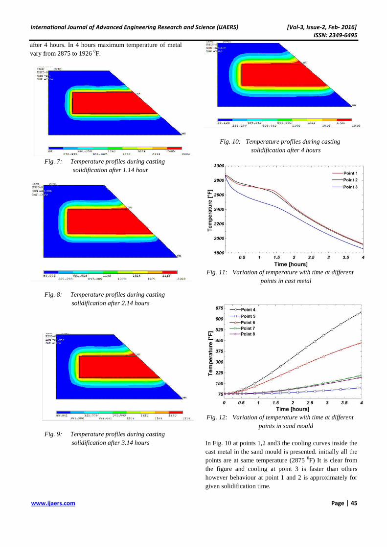
after 4 hours. In 4 hours maximum temperature of metal vary from 2875 to 1926 0F.
Fig. 7: Temperature profiles during casting
solidification after 1.14 hour
Fig. 8: Temperature profiles during casting
solidification after 2.14 hours
Fig. 9: Temperature profiles during casting
solidification after 3.14 hours
Fig. 10: Temperature profiles during casting
solidification after 4 hours
Fig. 11: Variation of temperature with time at different
points in cast metal
Fig. 12: Variation of temperature with time at different
points in sand mould In Fig. 10 at points 1,2 and3 the cooling curves inside the cast metal in the sand mould is presented. initially all the points are at same temperature (2875 0F) It is clear from the figure and cooling at point 3 is faster than others however behaviour at point 1 and 2 is approximately for given solidification time.
International Journal of Advanced Engineering Research and Science (IJAERS) [Vol-3, Issue-2, Feb- 2016]
ISSN: 2349-6495
www.ijaers.com Page | 46
Fig. 11 shows at different points the variation of temperature with time in the sand mould. Cause of large heat rejection by molten metal, temperature of sand mould increases and heating curves are shown in figure at different locations. Point 4 is the most critical location during casting it is clear from the figure it is due to symmetry of the casting. Chills can be used at that position to increase heat transfer rate.
V. CONCLUSIONS Present work is an attempt to casting simulation using ANSYS has been carried out to obtain the temperature variation with time at different points. 1. ANSYS provides an effective way to study the
solidification of different materials under different mold designs and materials.
2. Details of temperature variations in cast metal are an important factor in improving the casting quality, reduced cost of development and speeding up the improvement of the product.
3. Variation of temperature with time at different points in sand mould, enable the designer to select correct size of the mould, positions for chills.
REFERENCE [1] Kalpakjian S. and Schmid S.R. “Manufacturing
Engineering and Technology” Prentice Hall, 2010 [2] Pariona, M.M., Bolfarini, C., Dos Santos, R.J. and
Kiminami, C.S., “Application of Mathematical Simulation and Factorial Design Method to the Optimization the Atomization Stage in the Forming of a Cu-6% Zn Alloy”, Journal of Materials Processing Technology,2000, vol.102, 221-229.
[3] Campbell, J., “Casting”, Butterworth-Heinemann, Oxford, 1991.
[4] Flemings, M.C., “Solidification processing”, McGraw-Hill, 1974.
[5] Ghosh A. and Mallik A.S., “Manufacturing science” EWP, 2006
[6] Choudhari C.M., Narkhede B.E., Mahajan S.K., “Modeling and Simulation with Experimental Validation of Temperature Distribution during Solidification Process in Sand Casting”, International Journal of Computer Applications, 2013, vol.16, 23-29.
[7] Gopinath V., Balanarasimman N., “Effect of Solidification Parameters on the Feeding Efficiency of Lm6 Aluminium Alloy Casting”, IOSR Journal of Mechanical and Civil Engineering, 2012, Vol. 4, 32-38.
[8] Pariona M.M. and Mossi A.C., “Numerical Simulation of Heat Transfer During the Solidification of Pure Iron in Sand and MulliteMolds” Journal of
the Brazil Society of Mechanical Science & Engineering,2005, Vol. 27, 399-406.
[9] Handbook ANSYS 12, ANSYS, Inc.