1.0 engineering reports - brisbane.qld.gov.au d02... · subdivision and development guidelines ......
TRANSCRIPT
Urban Management DivisionSubdivision and Development GuidelinesPart D Design & Construction Procedures
November 2004i
TABLE OF CONTENTS
1.0 ENGINEERING REPORTS .................................................................................. 11.1 GENERAL ......................................................................................................... 11.2 GEOTECHNICAL ASSESSMENT..................................................................... 11.3 HYDROLOGIC AND HYDRAULIC ASSESSMENT........................................... 1
1.3.1 Objective ..................................................................................................... 11.3.2 Standard...................................................................................................... 11.3.3 General ....................................................................................................... 11.3.4 Plans and Figures ....................................................................................... 21.3.5 Cross Sections and Longitudinal Sections.................................................. 21.3.6 Model Schematisations ............................................................................... 31.3.7 Report Structure.......................................................................................... 31.3.8 Mathematical Models .................................................................................. 41.3.9 Manual Calculations.................................................................................... 51.3.10 Resubmissions............................................................................................ 5
2.0 DRAWINGS.......................................................................................................... 62.1 GENERAL ......................................................................................................... 62.2 STANDARDS .................................................................................................... 6
2.2.1 General ....................................................................................................... 62.2.2 Sheet Sizes................................................................................................. 62.2.3 Scales ......................................................................................................... 72.2.4 Survey Datum ............................................................................................. 72.2.5 Dimensioning .............................................................................................. 7
2.3 FUNCTIONAL TRAFFIC LAYOUT .................................................................... 82.4 STREET NAMING AND NUMBERING.............................................................. 92.5 LANDSCAPE MANAGEMENT AND SITEWORKS PLAN................................. 92.6 TRAFFIC SIGNS AND PAVEMENT MARKING .............................................. 112.7 LEADING DRAWING ...................................................................................... 142.8 EARTHWORKS............................................................................................... 142.9 ROADS............................................................................................................ 14
2.9.1 Layout ....................................................................................................... 142.9.2 Longitudinal Section.................................................................................. 152.9.3 Cross Section............................................................................................ 152.9.4 Details ....................................................................................................... 16
2.10 STORMWATER DRAINAGE........................................................................... 172.10.1 Layout ....................................................................................................... 172.10.2 Longitudinal Section.................................................................................. 172.10.3 Details ....................................................................................................... 18
2.11 ASSET REGISTER ......................................................................................... 20

Page left blank intentionally
Urban Management DivisionSubdivision and Development Guidelines
Part D Design & Construction Procedures
November 20041
1.0 ENGINEERING REPORTS1.1 GENERAL
This section is intended to provide guidance to Developers and Consultants in thepreparation of engineering reports as part of the submission to support the developmentapplication.
Prior to any engineering assessment, it is recommended that the terms of reference bediscussed with Council to establish a clear understanding of issues, methodologies, andreport objectives. A suitably qualified Registered Professional Engineer Queensland(RPEQ) should certify all engineering submissions.
Unless noted otherwise, Council submission should comprise: Three (3) sets of hardcopy reports and supporting plans. If required, a digital copy (floppy diskette or CD-ROM) of mathematical modelling
input and output files.
1.2 GEOTECHNICAL ASSESSMENTThe report should cover stability and erodility issues including but not limited to: Visual aspects of the site. Conditions of the area. Soil characterisation. Probability of slip failure. Factor of safety. Impacts of development on surface water runoff. Measures to mitigate soil movement. Recommendations.
1.3 HYDROLOGIC AND HYDRAULIC ASSESSMENT1.3.1 Objective
Hydrologic and hydraulic submissions should demonstrate that the proposeddevelopment would not adversely impact on flooding to upstream, downstream oradjacent properties. The reliability of the assessment approach should be proventogether with the accuracy of the base data used.
1.3.2 StandardThe hydrologic and hydraulic assessment report should be of standard that address therequirements set out in subsequent Sections 1.3.3 to 1.3.10.
1.3.3 GeneralApplication detailsReport should include property address, development name (if applicable) anddevelopment application reference number.
Report certificationReport should include author’s name and qualifications and signed/certified by anRPEQ suitably qualified in the field of drainage/hydraulic investigations. The date and

Urban Management DivisionSubdivision and Development Guidelines
Part D Design & Construction Procedures
November 20042
version number of the report should be clearly presented on a Document Control pageat the start of the report.
Transfer of copyrightAll reports submitted to Council should state that both the report and associatedcomputer data files may be used by the Brisbane City Council in the future, for whateverpurposes the Council requires.
1.3.4 Plans and FiguresEvery report should include: A locality plan. A catchment plan detailing internal and external drainage catchments and their
respective areas. A site plan describing the site in its existing state. A proposal plan describing the proposed works generally, including staging. Where applicable, the details of drainage easements associated with underground
drainage, open channel drainage or overland flow paths should be clearlypresented. In the case of overland flow paths, finished ground surface levels shouldbe shown.
Where applicable, a comparison of existing and proposed extents of floodinundation should be presented.
Where applicable, detailed plans for any proposed waterway structures, which aresigned/certified by an RPEQ.
Catchment plans, site plans and proposal plans should be drawn to scale. Site plansand proposal plans should show and clearly distinguish between existing and proposedground levels and surface treatments. The source of ground survey data should beclearly identified. Generally, only certified survey from a registered surveyor will beaccepted. Extents of existing and proposed structures should be included.
The level of detail required to describe proposed works may vary depending on the levelof development approval sought. All reports submitted in support of Applications forOperational Works and/or Building Work should specifically refer to engineeringdrawings that define the proposed works. The drawings should show the proposedextent and levels of filling and excavation relative to cadastral boundaries. WaterwayCorridors, if present, should be shown. For dams and retention basins, plans shouldinclude cross sections of embankments, spillways and any other inlet and/or outletstructures.
1.3.5 Cross Sections and Longitudinal SectionsReports should include plots of cross sections for both the pre and post developmentcases. These plots should in some way enable the cross-referencing of groundcoordinates on a cross section plot to the plan view of ground level contours (or spotlevels) and the hydraulic model data files. For this reason, cross sections should bedrawn to scale and include: Cadastral boundaries, or a survey traverse line of adequate dimensions, so as to
allow the cross section coordinates to be accurately transcribed onto a plan, inrelation to cadastral boundaries.
At least two offset stations (x-value) shown within the cross section to facilitatecomparison with the cross section coordinates within the model data files.

Urban Management DivisionSubdivision and Development Guidelines
Part D Design & Construction Procedures
November 20043
The report should also include plots of cross sections located downstream of theproposed development site, and particularly those which the analysis identifies as actingas flow controls. Such cross sections would usually be associated with culverts andbridges, weirs and causeway, and flow constrictions.
The supporting drawings should include a longitudinal section of all proposed drainageworks. Starting tailwater levels used in the hydraulic grade line analysis are to beclearly shown.
1.3.6 Model SchematisationsLayouts of mathematical models should be clearly shown in the report. It is essentialthat the report include plans showing the locations of model cross sections for both thepre and post development cases. These plans should be to scale and include cadastralboundaries. Alternatively, a survey traverse line, which can be linked back to cadastralboundaries, may be included.
For major hydraulic studies involving extensive creek/river modelling, cross sectionsshould be marked on an aerial photograph base. The plan should indicate on eachsection the extents of each roughness segment and the value of its roughnessparameter. If there are construction works involved then the ultimate layout should alsobe shown on this plan, but in a contrasting colour so that scenarios can be compared.
1.3.7 Report StructureThe report should be structured to include: Objectives of the report. Reference to any previous or associated reports. Brief description of the development proposal and background details. How the relevant hydrologic, hydraulic and drainage issues are addressed. Clear description of the assessment methodology used, including justification and
any limitations or assumptions. Discussion on the sensitivity analyses undertaken for the proposal, including
identification and justification of the adopted parameters and/or results. Hydraulic results for should be summarised in clearly formatted tables. The results
should include cross section reference, design discharges, water surface levels,energy grade lines, flow velocities, flow depths, depth velocity product, etc. Therelative differences between the results of pre and post development scenariosshould also be presented. Other modelling results should be included where theseare needed to justify the acceptability of the proposal. Comprehensive modellingresults should be incorporated into an appendix. Where possible, the resultspresented should be verified by other valid “quick check” methods such as handcalculations. For example, modelled head loss values may be verified usingmanual calculation methodologies outlined in the publication Waterway Design: AGuideline to the Hydraulic Design of Bridges, Culverts and Floodways (Austroads,1994).
Conclusions that summarise the analysis results/findings and any impacts createdby the proposal. Conclusions should include a clear statement as to why thereport/proposal should be approved.
A listing of all references used. If the reference is obscure, photocopies of therelevant sections of the source material should be provided.

Urban Management DivisionSubdivision and Development Guidelines
Part D Design & Construction Procedures
November 20044
1.3.8 Mathematical ModelsModelling softwaresTo enable timely assessment by Council within the nominated response timeframe, thefollowing industry standard modelling softwares should be used. (Note: Where donatedassets are involved, the softwares listed below should be used to enable integrationwith Council database system). Runoff routing hydrologic models: RAFTS, WBNM. Drainage analysis: DRAINS (ILSAX), XP-STORM (SP-UDD), PC-Drain. Steady state hydraulic model: HEC-RAS (developed by the US Army Corps of
Engineers). Unsteady flow hydraulic model: MIKE-11 hydrodynamic model (developed by the
Danish Hydraulic Institute).
Other mathematical modelling softwares may be accepted but this should be checkedwith Council prior to the commencement of any model simulations. As a minimum, thesubmission should be accompanied by: Basic parameters. Input data files. Output summary files. Relevant documentation relating to the program to enable deciphering and
interpretation of the input and output files. Verification of models using industry standard techniques. For example, predicted
peak discharges may be checked using the Rational Method, and predicted peakflood levels may be checked with a basic HEC-RAS backwater model.
Model setupA general description of the model setup should be included in the report. Theinformation provided should enable the reader to understand how the variouscharacteristics of the site and/or catchment have been incorporated into the submittedmodel.
Model parameters and assumptionsThe report should justify the basis of the values adopted for the hydrologic and hydraulicmodelling parameters used in the analysis. Parameters to be considered include, butare not limited to: Rainfall loss values. Sub-catchment fraction imperviousness. Flow velocity estimates. Manning’s ‘n’ roughness values. Flow contraction and expansion coefficients. Structure hydraulic headloss coefficients. Other hydraulic headlosses.
In presenting hydrologic calculations, the report should define the ultimate land uses ofthe upstream catchment and the waterway/overland flow treatments that act tocharacterise flow velocities and times of concentration.
Urban Management DivisionSubdivision and Development Guidelines
Part D Design & Construction Procedures
November 20045
Hydraulic calculations should include a description of downstream flow controls. Thereport should explain the basis for the values of the starting water levels adopted in aHydraulic Grade Line calculation for pipe flow, or backwater analysis. The report shouldalso explain the assumptions used in the analysis of waterway structures.
Exceptions to default parametersReports describing studies of extensive river systems and large catchments ofteninvolve a large amount of data and hence involve the estimation and incorporation of alarge number of hydraulic parameters. It is not uncommon in such reports that thevalues of certain parameters are held constant over the entire analysis, effectivelyascribing “default” values to these parameters. This may be acceptable, however, thereport should clearly state where exceptions to these default values have been used. Itis preferable that both the default values and these exceptions are summarised in theform of a table.
Model calibrationThe demonstration of the calibration of a computer model (where required) should bepresented in the form of a table of results. The table should compare modelled resultswith either recorded data or results obtained by other valid methods of calculation.Variations between the data sets should be explained and justified. Where appropriate,the results of a consistency check between hydrologic and hydraulic model dischargesshould be presented.
Computer model filesThe report should include a comprehensive listing of the computer model files used inthe hydraulic assessment together with an explanation as to what these files represent.Any naming conventions used should be clearly explained. Particular model executionparameters such as modelling timesteps, run durations, etc, should also be included.
1.3.9 Manual CalculationsHand calculations should be legible and presented neatly in a logical and easy-to-followformat. Equations and/or information sources used in the analysis should bereferenced, and if the reference is obscure, then photocopies of the relevant sections ofthe source material should be provided. The adopted analytical parameters should besubstantiated with explanations.
1.3.10 ResubmissionsMajor amendmentsMajor amendments generally have an impact over the entire report. Theseamendments may be required at such times following a change in the developmentproposal layout, changes in the approach to the analysis or modelling, or errors in thecalculations and results. Major amendments should be reported by a full resubmissionof the report, with a new Revision Letter shown on the Document Control page.Amended reports should be written so that the reader is not required to refer to previousreports or Council files in order to understand the report. Resubmissions should clearlyreference the previously submitted reports.
Minor amendmentsIn cases where amendments are deemed to be minor, involving only the correction of acouple of pages, resubmission of only the amended pages may be satisfactory,provided that an updated Document Control page is also submitted showing the newRevision Letter for the report.

Urban Management DivisionSubdivision and Development Guidelines
Part D Design & Construction Procedures
November 20046
Additional informationIn instances where additional information is provided in support of a report, theinformation may be provided as an Addendum Report or Appendix to the report. This ison the basis that the additional information is not based on a proposal layout, data,calculations, results or recommendations which conflict with the original report; anddoes not require further clarification of how this additional information relates to theoriginal report.
An example of such information would be a table of results for an average recurrenceinterval storm different to that provided in the original report (provided that all underlyingcalculations are based on the same approach as that used in the original report).
2.0 DRAWINGS2.1 GENERAL
This section is intended to provide guidance to Developers and Consultants in thepreparation of engineering, architectural and landscape drawings as part of thesubmission to support the development or operational work applications. Drawingsshould reflect the intent of these guidelines and the professionalism of the Consultant indesigning works that are fit for purpose.
All engineering drawings should be uniquely referenced and require the full signature ofa suitably qualified engineer, registered with the Board of Professional Engineers,Queensland and the RPEQ number and date, in the title block.
Unless noted otherwise, Council submission should comprise five (5) sets of drawingsin one of the following forms: Two sets of A1 and three sets of A3. Typically this applies to major subdivisions. Five sets of A3. Typically this applies to smaller developments where the resolution
of the A3 is sufficient to depict the proposed works.
2.2 STANDARDS2.2.1 General
The draftsmanship should be of a standard that is normally accepted in good civilengineering and architectural practice, generally in accordance with the requirements ofAS 1100 Technical Drawing. Substandard drawings and poorly presented calculationtables may be rejected. In this instance, the applicant may be required to resubmitplans accompanied by any additional payable fees.
2.2.2 Sheet SizesThe preferred sizes of drawing sheets are: A1 size (594 mm x 841 mm cut sheet dimensions). A3 size (297 mm x 420 mm cut sheet dimensions).

Urban Management DivisionSubdivision and Development Guidelines
Part D Design & Construction Procedures
November 20047
2.2.3 ScalesThe chosen scale for a drawing should permit easy and clear interpretation of theinformation depicted. Where full size drawings are reduced, appropriateblock/graduated or prefix scales should be provided to enable interpretation ofdimensions specified in the reduction copies.
The preferred scales for use should generally conform to the recommendations ofAS 1100. The recommended scales are 1:1, 1:2, 1:5 and multiplying theaforementioned scales by integral powers of 10. Multiples and submultiples of 10 forscales 1:25 and 1:125 are not preferred but may be accepted.
The following scales are suggested for particular uses but these may be varied asappropriate to the works concerned. Plans - 1:1000 or 1:500. Roofwater reticulation layout plans should be drawn in the
1:500 scale. Longitudinal Sections - Horizontal 1:1000 and Vertical 1:100 or Horizontal 1:500
and Vertical 1:50. Intersection Details - 1:200, 1:100 or 1:250. Cross Sections - 1:100. Engineering Details - 1:20 or 1:10.
2.2.4 Survey DatumLevel information should be referenced to the Australian Height Datum (AHD). Positioncoordinates should be tied to the GDA94 datum based on the Mapping Grid of Australia(MGA) coordinate system.
2.2.5 DimensioningUnitsAll dimensions should be expressed in metric units. Linear dimensions on all roadworksplans should be in metres, with the exception of some detail plans of small structures(eg manholes) and some standard plans (eg kerb and channel), which may be inmillimetres.
LevelsReduced levels of benchmarks and reference pegs including permanent survey marksshould be expressed to three decimal places eg 0.001 m. Reduced levels of roadworksand stormwater drainage may be expressed rounded to three decimal places eg0.001 m.
ChainagesChainages on plans should be expressed to three decimal places eg 0.001 m.
Cross section intervalsRoad cross sections should be provided at 20.0 m intervals, with further subdivision of10.0 m to 5.0 m intervals where necessary at horizontal or vertical curvatures.
GradesRoad and pipe grades should be shown to three significant figures eg 2.300%.
Urban Management DivisionSubdivision and Development Guidelines
Part D Design & Construction Procedures
November 20048
2.3 FUNCTIONAL TRAFFIC LAYOUTTo avoid the need for changes to detailed design of roadworks in respect of horizontalalignments, intersections, channelisations and the like, the functional layout plansshould be submitted to Council for approval. One (1) set of the approved subdivisionlayout plans should accompany the application before any assessment canproceed. Once functional layouts are approved, the detailed engineering design canbe undertaken.
Approved functional layout plans that also incorporate traffic signs and/orpavement markings does not obviate the need of the applicant to submit aseparate application for the approval of traffic signs and pavement markingdrawings (refer Section 2.6).
Functional layouts submitted by the applicant should show at least the followinginformation:
1. Background information that includes: Design philosophy or concept description. Design speed for each road type. Reasons for access arrangement.
2. A plan, drawn to scale, showing all relevant existing details, that includes: Land use of adjacent sites and sites opposite the development. Existing intersections and vehicular entrances in the vicinity. Existing road layout. Existing services which have an impact on the layout. Existing pavement marking. Existing trees.
3. Proposed roadworks/channelisation layout, drawn to scale, that includes: Critical dimensions. Proposed pavement marking, including lane marking with lane widths. Relationship of work with other stages. Limit of Brisbane City Council responsibility where other authorities are involved
eg Queensland Department of Main Roads. All allotments and property boundaries.
4. Any other information considered necessary by the Council to adequately assessthe performance of the facility.
The 1:250 scale is recommended for intersections and 1:500 scale for more extensiveroadworks. A North Point should be shown on all plans. If the development is at ornear an intersection, a plan of the entire intersection is required ie showing all existinglegs (not part of the intersection only).
Urban Management DivisionSubdivision and Development Guidelines
Part D Design & Construction Procedures
November 20049
2.4 STREET NAMING AND NUMBERINGApplications and plans for proposed street names and numbers should be lodged withLicensing Sealing & Certificates Unit, Development & Regulatory Services. One (1) setof the approved subdivision layout plans and one (1) set of the approvedfunctional layout plans should accompany the application before any assessmentcan proceed. Eight (8) sets of street naming and numbering plans, preferably in A3sizes, should be submitted. It is recommended that this application be lodged forapproval as soon as possible after functional layout plan approval to avoid any delay insealing the survey plan in the event that the street names applied for are not approvedand need to be resubmitted.
2.5 LANDSCAPE MANAGEMENT AND SITEWORKS PLANLandscape Management & Siteworks Plans1 are generally submitted as part of theoperational works application. The plans should be prepared by a suitably qualifiedLandscape Architect or Designer.
Street plantingWhere the Developer elects to undertake landscaping of the road reserve instead ofpaying a monetary contribution, detailed landscape plans showing at least the followinginformation should be submitted:1. Road layout with property boundaries and lot numbers.2. Road names.3. Landscaping and tree planting within road reserve including roundabouts, speed
control devices, and traffic islands.4. All features relating to the landscaping such as concrete footpaths, mowing strips,
retaining walls, fences, etc.5. Location of trees, shrubs, etc with names and spacings.6. A schedule of plant species with botanical and common names.7. Any existing trees on site that will be retained.8. The exact location of water meters and taps, if required.9. Position of temporary irrigation system for the duration of the maintenance period.10. Typical detail of planting hole which should include mulch type and depth, location
of weed mat, depth and type of soil mix, root barrier, detail of drainage layers, etc.11. The area (m2) of landscaping should be shown on the asset register.12. Any landscaping associated with acoustic fencing, entrance features, street
furniture, etc.
1 Landscape Management & Siteworks Plan is the accepted Council terminology, but the plan can be
referred to by other names such as a Landscape Plan.

Urban Management DivisionSubdivision and Development Guidelines
Part D Design & Construction Procedures
November 200410
Park embellishmentLandscape plans pertaining to park embellishment are required to show existing andproposed details including but not limited to:1. Plan/s and section/s.2. Contours and levels.3. Existing vegetation and vegetation protection and management provisions.4. Existing natural features to be retained and protected (eg wetlands, waterways, rock
formations, etc).5. Details of proposed hard and soft landscape construction works (eg planting plan,
plant species schedule, surface treatments, structures).6. Details of manufacturer and/or type of park equipment to be used in construction,
such as play equipment, furniture etc.7. The location of any stormwater quality management infrastructure to be constructed
in the park including maintenance access to the infrastructure.8. Reports on innovative works or infrastructure that contributes to achievement of the
Desired Environmental Outcomes outlined in Brisbane City Plan.9. A list of all major structural components, plumbing, playgrounds and heritage
management works, etc, requiring private certification, including works requiringRegistered Professional Engineer Queensland (RPEQ) certification.
10. A program of proposed maintenance works during the maintenance period,including monthly inspection reports to be submitted to Council detailing compliancewith maintenance requirements.
11. An estimate of value of all assets to be provided in the park (eg fencing, picnicshelters, shade structures) for future asset management purposes.
12. An estimate of the likely annual operational and maintenance costs once the park isestablished and handed over to Council, for park maintenance and life cyclebudgeting purposes.
13. Names and contact numbers of the developer, including the developer’srepresentative, the Landscape Architect/Designer, the engineers responsible for thedesign and private certification of any engineering works and the landscapecontractor (if known at the time).
Council Delegate will only approve the Landscape Management and Siteworks Planthat demonstrates compliance with the following minimum park standards, as specifiedin Chapter 8 of Part B of this document. Construction of vehicle barriers/bollards to prevent unauthorised access. Provision of a 25 mm reticulated water service and water meter. Provision of an electricity supply pillar. Removal of all weeds. Provision of earthworks, levelling, topsoiling and grassing, with perennial grasses,
suitable for mowing to all open ground. Removal of dead trees or branches that may present a public risk. Removal of all rubbish.
Urban Management DivisionSubdivision and Development Guidelines
Part D Design & Construction Procedures
November 200411
Details of other works proposed in the park, which do not form part of the LandscapeManagement & Siteworks Plan, should be referred to on the plan (eg VegetationManagement, Rehabilitation and Environmental Management plans). The design andmanagement of the park should be incorporated into the Erosion and Sediment ControlPlan (refer to conditions of Development Approval).
Specific written approval is required where ancillary works are proposed in existingparks, such as stormwater discharge through a park into a waterway. Approval for thiswork should be obtained prior to the operational works application stage.
2.6 TRAFFIC SIGNS AND PAVEMENT MARKINGApplications and plans for traffic signs and pavement markings should be lodged withCouncil for approval. The initial submission should comprise two (2) sets of hardcopypaper plans. One (1) set of the approved road layout plans and one (1) set of theapproved street naming and numbering plans should accompany the application,before any assessment can proceed.
The 1:250 or 1:500 scale plans should be drawn using Brisbane City Council’s standardtemplates such as title blocks and symbols. The plans should also incorporate theConsultant’s logo (the applicant can elect to use Brisbane City Council or an externalengineering consultant) and Council’s designated traffic area identification number.
The plans will need to incorporate existing and proposed details including but not limitedto:1. Real property boundaries and kerb lines.2. Driveways.3. Pavement marking. Existing markings that will be retained and proposed markings
should be fully dimensioned. Thin dashed line should be used for existing markingsthat will be removed. Refer typical example given in Figure D.1.1.
4. Signs eg parking signs, street name signs, etc. Proposed traffic signs should beshown using the standard sign code eg ERECT R2-14(L) and not shown as pictorialsigns. Refer typical example given in Figure D1.1.
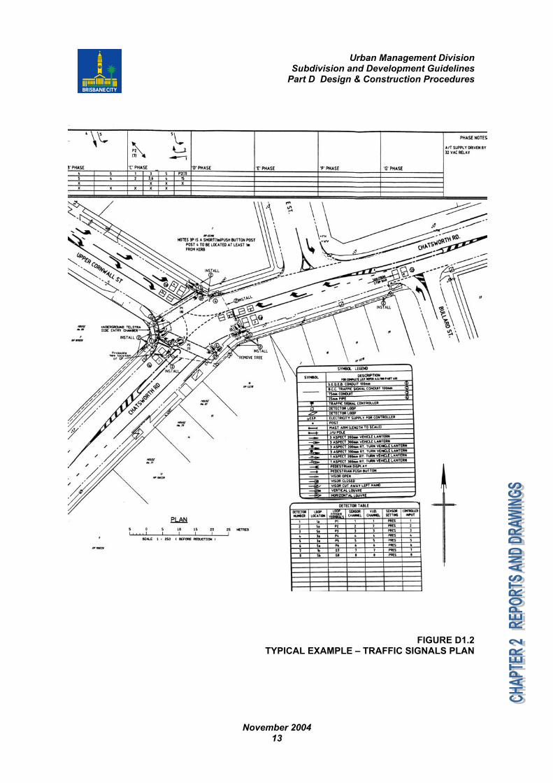
5. Power poles and service pits.6. Traffic signals. Refer typical example given in Figure D1.2.7. The preferred future road layout where the proposed streets may be in the future
loop roads of cul-de-sacs.8. Locality plan (for jobs proposing new roads).
The final submission should comprise: One (1) A1 size hardcopy on film. Three (3) A1 size hardcopies on paper. Electronic digital file (preferably AutoCAD drawing file) on floppy disk or CD-ROM.

Urban Management DivisionSubdivision and Development Guidelines
Part D Design & Construction Procedures
November 200412
FIGURE D1.1TYPICAL EXAMPLE - SIGNS AND PAVEMENT MARKING PLAN
Urban Management DivisionSubdivision and Development Guidelines
Part D Design & Construction Procedures
November 200413
FIGURE D1.2TYPICAL EXAMPLE – TRAFFIC SIGNALS PLAN

Urban Management DivisionSubdivision and Development Guidelines
Part D Design & Construction Procedures
November 200414
2.7 LEADING DRAWINGThe leading drawing of the set of plans should contain the following information:1. Council file reference number.2. Site address (as per application).3. Locality plan, clearly showing the stage boundary and adjacent stages if applicable.4. Drawing index, including plans for other stages if applicable.5. List of all Council standard drawings used.6. List of all Consultant's standard drawings used (copies should be attached).7. Full legend.8. Asset register, refer Section 2.11.
2.8 EARTHWORKSEarthworks drawings are required to show all the following information:1. Any contaminated soil areas.2. Existing surface contours and/or levels.3. Finished surface contours and/or levels.4. Areas of cut.5. Areas of fill and indicating any requirement for imported fill.6. Slopes of cut batters and fill embankments.7. Location and height of any earth retaining structures, such as boulder walls,
concrete retaining walls, crib walls, etc.8. Access to properties where crossfall of allotments is severe.9. Details of minimum habitable floor levels should be clearly identified on the layout
plan where allotments are filled to provide flood immunity.10. Locations of soil stockpiles.11. Indicate proposed methods for dust control.12. Areas subject to Vegetation Protection Order.13. Where cut and fill operations are near the boundary of adjoining private properties
or public space, cross sections should be provided showing the finished levels andpositions in relation to the property boundaries. Surface levels and any structures inthe adjoining land should be shown. Also refer to Chapter 3 of Part B of thisdocument.
14. Details of proposed ground anchoring system. Refer to Chapter 3 of Part B of thisdocument for requirements.
2.9 ROADS2.9.1 Layout
One (1) set of the approved functional layout plans should accompany the roaddrawings before any assessment can proceed. Road layout plans are generallyrequired to show the following information:1. Legend.2. Road reserve boundaries including any widening, and road identification.3. Allotment boundaries with proposed lot number.4. Road centreline, chainages, and bearings including chainages and centreline of
intersecting streets.
Urban Management DivisionSubdivision and Development Guidelines
Part D Design & Construction Procedures
November 200415
5. Dimensioned road reserve, footpaths, pavement widths that are different from thestandard cross section.
6. Location of existing services.7. Proposed contours.8. Proposed easements.9. Stage boundaries.10. Horizontal curve data.11. Traffic islands.12. Concrete footpaths.13. Concrete bikeways.14. Cut-off drains.15. Vehicular crossings.16. Areas of paver/stencil concrete treatment.17. Side drains.18. Location of guardrails and fences.19. Pavement tapers.
2.9.2 Longitudinal SectionRoad longitudinal section drawings are generally required to show the followinginformation:1. Chainages.2. Existing surface levels.3. Design road centreline.4. Design kerb lip levels.5. Cut and fill depths and/or volumes.6. Grades.7. Chainages and levels of grade intersection points.8. Chainages and levels of tangent points of vertical curves.9. Chainages and levels of crest and sag points.10. Lengths and radii of vertical curves.11. Superelevated curves.12. Minimum or nominal asphalt surfacing and pavement thickness.13. Scales.14. Road names.15. Datum.
2.9.3 Cross SectionDrawings of typical road cross sections are generally required to show all the followinginformation, whereas items 10-12 are generally sufficient to depict the other sections.1. Road reserve width.2. Pavement widths.3. Footpath widths.4. Crossfall of pavement and footpath.5. Pavement under kerb and channel, shoulder, traffic islands.6. Existing services and proposed services.7. Type of kerb and channel.
Urban Management DivisionSubdivision and Development Guidelines
Part D Design & Construction Procedures
November 200416
8. Subsoil drainage.9. Road names.10. Chainages.11. Datum.12. Natural surface and finished levels.13. Position and size of concrete footpath/bikeway.14. Traffic islands.
2.9.4 DetailsIntersections/road wideningDrawings are generally required to show the following information:1. Road names.2. Stormwater drainage.3. Lip levels.4. Curve radius.5. Adjacent lot numbers, point chainage and offset.6. Tangent.7. Road reserve.8. Pavement contours at sufficient intervals.9. Channelisation works.10. Surface treatments.11. Concrete footpath crossings/bikeway crossings.
Speed control devicesDrawings are generally required to show the following information:1. As per intersections/road widening above.2. Island geometry and levels.3. Product code of devices.4. Radii, chainage and offsets.5. Island kerb.6. Landscape area.
PaversDrawings are generally required to show the following information:1. Restraints.2. Pavements.3. Drainage.4. Type of paver eg colour, size, material, product code, manufacturer, etc.
Urban Management DivisionSubdivision and Development Guidelines
Part D Design & Construction Procedures
November 200417
2.10 STORMWATER DRAINAGE2.10.1 Layout
Stormwater drainage layout plans are generally required to show the followinginformation:1. Legend.2. Road reserve boundaries and road identification.3. Allotment boundaries with proposed lot number.4. Location of stormwater and roofwater lines (including size), manholes, gullies,
outlets, inlets, roofwater inspection pits, etc.5. Location of existing services.6. Existing and proposed contours.7. Proposed easements.8. Stage boundaries.9. Concrete footpaths.10. Concrete bikeways.11. Cut-off drains.12. Vehicular crossings.13. Side drains.14. Location of flood regulation lines.15. Position of the waterway eg centreline and top of bank.16. Extents of overland flow path including cross sectional details.17. Roofwater kerb adaptors in the kerb and channel.18. Drawings should incorporate note that outlets in public space and waterways should
be inspected before construction. Stormwater outlets in any public space (existingor newly created Council asset) should be addressed at the initial application(conceptual design) stage and not be deferred to the operational works assessmentstage, as the method of stormwater conveyance and treatment could influence thedevelopment’s design, layout and cost. Also refer to Chapter 6 of Part B of thisdocument.
2.10.2 Longitudinal SectionStormwater drainage longitudinal section drawings are generally required to show thefollowing information:1. Chainages.2. Existing surface levels.3. Design finished surface levels.4. Pipe invert levels.5. Manhole chainages.6. Distance between manholes.7. Grade of pipes.8. Pipe capacity.9. Pipe size.10. Diameter of pipes.11. Pipe class eg Class 2.12. Pipe installation type eg H2 trench.

Urban Management DivisionSubdivision and Development Guidelines
Part D Design & Construction Procedures
November 200418
13. Trench construction method eg excavator wheel load, wacker packer, etc.14. Hydraulic grade line including the corresponding water levels at junctions.15. Design storm frequency.16. Manhole diameters.17. Invert levels of inlets/outlets. Details should be extended to include the free outlet
or creek bed.18. Gully numbers.19. Depth to invert at manholes.20. Datum.21. Type of gully and size of lintel.22. Service crossing.
2.10.3 DetailsManholesDrawings are generally required to show the following information:1. Connecting pipes.2. Manhole/chamber size.3. Identification number.4. Location chainage.
Inlets/outletsDrawings are generally required to show the following information:1. Identification number2. Thickness of walls and floor.3. Reinforcing.4. Type of treatment to prevent scour, eg energy dissipator.5. Water quality management devices eg gross pollutant trap, sedimentation basin.6. Type of grate – galvanised.7. Surrounding levels eg waterway bed and banks.8. Position in relation to waterway, property boundary, flow direction, flow velocity, etc.9. Invert levels.10. Surcharge structures.
Catchment planDrawings are generally required to show the following information:1. Tabulation of catchment areas, slopes, runoff coefficient, design discharges, etc.2. Layout with gully catchments.3. Full external catchment with contours extending beyond the limits of the site.4. Existing and proposed contours.
Stormwater drainage calculation sheetRefer template outlined in Supplement to QUDM, Chapter 2 of Part B of this document.
Urban Management DivisionSubdivision and Development Guidelines
Part D Design & Construction Procedures
November 200419
Open channelDrawings are generally required to show the following information:1. Top and toe of batters.2. Cross sections.3. Design levels.4. Existing surface levels either by contours or spot levels, on the subject site and on
the adjoining properties or road reserves.5. Proposed spot levels and contours.6. Proposed development and habitable floor levels.7. Maintenance and/or safety berms.8. Longitudinal section.9. Landscaping details.
Detention/retention basinDrawings are generally required to show the following information:1. As per Open Channel above.2. Side batters.3. Spillway.4. Low flow pipes.5. Floor subsoil drainage.
CulvertsDrawings are generally required to show the following information:1. Full structural details.2. Handrails.3. Scour protection.
Overland flow pathsDrawings are generally required to show the following information:1. Existing surface levels, either by contours or spot levels, on the subject site and on
the adjoining properties or road reserves or waterways.2. Finished surface levels on the subject sites.3. Proposed habitable floor and development levels.4. Overland flow path widths and levels, and cross sections along the flow path for the
design flows.5. Existing drainage structures, including pipe sizes and levels, especially at the
proposed discharge point.6. Overland flow paths for the design storm other than in road reserves should be
shown on separate drawings.