10 compound miter saw - delta machinery 899935.pdf3 additional safety rules for miter saws 1. use...
TRANSCRIPT

INS
TRU
CTIO
NM
AN
UA
L10" Compound Miter Saw
(Model 36-225)
PART NO. 899935 - 03-14-02Copyright © 2002 Delta Machinery
ESPAÑOL: PÁGINA 21To learn more about DELTA MACHINERY visit our website at: www.deltamachinery.com.For Parts, Service, Warranty or other Assistance,
please call 1-800-223-7278 (In Canada call 1-800-463-3582).

2
GENERAL SAFETY RULESWoodworking can be dangerous if safe and proper operating procedures are not followed. As with all machinery, thereare certain hazards involved with the operation of the product. Using the machine with respect and caution will con-siderably lessen the possibility of personal injury. However, if normal safety precautions are overlooked or ignored, per-sonal injury to the operator may result. Safety equipment such as guards, push sticks, hold-downs, featherboards,goggles, dust masks and hearing protection can reduce your potential for injury. But even the best guard won’t makeup for poor judgment, carelessness or inattention. Always use common sense and exercise caution in the workshop.If a procedure feels dangerous, don’t try it. Figure out an alternative procedure that feels safer. REMEMBER: Yourpersonal safety is your responsibility.
This machine was designed for certain applications only. Delta Machinery strongly recommends that this machine notbe modified and/or used for any application other than that for which it was designed. If you have any questions rela-tive to a particular application, DO NOT use the machine until you have first contacted Delta to determine if it can orshould be performed on the product.
Technical Service ManagerDelta Machinery4825 Highway 45 NorthJackson, TN 38305
(IN CANADA: 505 SOUTHGATE DRIVE, GUELPH, ONTARIO N1H 6M7)
WARNING: FAILURE TO FOLLOW THESE RULES MAY RESULT IN SERIOUS PERSONAL INJURY
1. FOR YOUR OWN SAFETY, READ INSTRUCTIONMANUAL BEFORE OPERATING THE TOOL. Learn thetool’s application and limitations as well as the specific haz-ards peculiar to it.
2. KEEP GUARDS IN PLACE and in working order.3. ALWAYS WEAR EYE PROTECTION. Wear safety
glasses. Everyday eyeglasses only have impact resistantlenses; they are not safety glasses. Also use face or dustmask if cutting operation is dusty. These safety glassesmust conform to ANSI Z87.1 requirements. NOTE:Approved glasses have Z87 printed or stamped on them.
4. REMOVE ADJUSTING KEYS AND WRENCHES. Formhabit of checking to see that keys and adjusting wrenchesare removed from tool before turning it “on”.
5. KEEP WORK AREA CLEAN. Cluttered areas andbenches invite accidents.
6. DON’T USE IN DANGEROUS ENVIRONMENT. Don’tuse power tools in damp or wet locations, or expose themto rain. Keep work area well-lighted.
7. KEEP CHILDREN AND VISITORS AWAY. All childrenand visitors should be kept a safe distance from work area.
8. MAKE WORKSHOP CHILDPROOF – with padlocks,master switches, or by removing starter keys.
9. DON’T FORCE TOOL. It will do the job better and besafer at the rate for which it was designed.10. USE RIGHT TOOL. Don’t force tool or attachment todo a job for which it was not designed.11. WEAR PROPER APPAREL. No loose clothing, gloves,neckties, rings, bracelets, or other jewelry to get caught inmoving parts. Nonslip footwear is recommended. Wear pro-tective hair covering to contain long hair.12. SECURE WORK. Use clamps or a vise to hold workwhen practical. It’s safer than using your hand and freesboth hands to operate tool.13. DON’T OVERREACH. Keep proper footing and bal-ance at all times.14. MAINTAIN TOOLS IN TOP CONDITION. Keep toolssharp and clean for best and safest performance. Followinstructions for lubricating and changing accessories.15. DISCONNECT TOOLS before servicing and whenchanging accessories such as blades, bits, cutters, etc.16. USE RECOMMENDED ACCESSORIES. The use ofaccessories and attachments not recommended by Deltamay cause hazards or risk of injury to persons.17. REDUCE THE RISK OF UNINTENTIONAL STARTING.Make sure switch is in “OFF” position before plugging inpower cord. In the event of a power failure, move switchto the “OFF” position.
18. NEVER STAND ON TOOL. Serious injury could occur ifthe tool is tipped or if the cutting tool is accidentally con-tacted.19. CHECK DAMAGED PARTS. Before further use of thetool, a guard or other part that is damaged should be care-fully checked to ensure that it will operate properly and per-form its intended function – check for alignment of movingparts, binding of moving parts, breakage of parts, mounting,and any other conditions that may affect its operation. Aguard or other part that is damaged should be properlyrepaired or replaced.20. DIRECTION OF FEED. Feed work into a blade or cut-ter against the direction of rotation of the blade or cutteronly.21. NEVER LEAVE TOOL RUNNING UNATTENDED.TURN POWER OFF. Don’t leave tool until it comes to acomplete stop.22. STAY ALERT, WATCH WHAT YOU ARE DOING, ANDUSE COMMON SENSE WHEN OPERATING A POWERTOOL. DO NOT USE TOOL WHILE TIRED OR UNDERTHE INFLUENCE OF DRUGS, ALCOHOL, OR MEDICA-TION. A moment of inattention while operating power toolsmay result in serious personal injury.23. MAKE SURE TOOL IS DISCONNECTED FROMPOWER SUPPLY while motor is being mounted, connect-ed or reconnected.24. THE DUST GENERATED by certain woods and woodproducts can be injurious to your health. Always operatemachinery in well ventilated areas and provide for properdust removal. Use wood dust collection systems wheneverpossible.25. WARNING: SOME DUST CREATED BY POWERSANDING, SAWING, GRINDING, DRILLING, ANDOTHER CONSTRUCTION ACTIVITIES contains chemi-cals known to cause cancer, birth defects or other repro-ductive harm. Some examples of these chemicals are:· lead from lead-based paints,· crystalline silica from bricks and cement and other
masonry products, and· arsenic and chromium from chemically-treated lumber. Your risk from these exposures varies, depending on howoften you do this type of work. To reduce your exposureto these chemicals: work in a well ventilated area, andwork with approved safety equipment, such as thosedust masks that are specially designed to filter out micro-scopic particles.
SAVE THESE INSTRUCTIONS. Refer to them often and use them to instruct others.

33
ADDITIONAL SAFETY RULES FORMITER SAWS
1. USE ONLY CROSS-CUTTING SAW BLADES.WHEN USING CARBIDE TIPPED BLADES, MAKESURE THEY HAVE A NEGATIVE HOOK ANGLE.
2. DO NOT OPERATE the miter saw until it is com-pletely assembled and installed according to the instruc-tions.
3. IF YOU ARE NOT thoroughly familiar with the oper-ation of compound miter saws, obtain advice from yoursupervisor, instructor or other qualified person.
4. DO NOT perform any operation freehand. Secure orclamp workpiece firmly against fence.
5. KEEP HANDS OUT OF PATH of saw blade. If theworkpiece you are cutting would cause your hand to bewithin hazard zone of the saw blade, the workpieceshould be clamped in place before making cut.
6. BE SURE blade is sharp, runs freely and is free ofvibration.
7. ALLOW the motor to come up to full speed beforestarting cut.
8. KEEP motor air slots clean and free of chips.
9. ALWAYS MAKE SURE all clamp handles are tightbefore cutting, even if the table is positioned in one ofthe positive stops.
10. BE SURE blade and flanges are clean and thatarbor screw is tightened securely.
11. USE only blade flanges specified for your saw.
12. NEVER use blades larger or smaller in diameter thanten inches.
13. NEVER apply lubricants to the blade when it isrunning.
14. ALWAYS check the blade for cracks or damagebefore operation. Replace cracked or damaged bladeimmediately.
15. NEVER use blades recommended for operation atless than 6000 RPM.
16. DO NOT operate the saw without guards in place.
17. ALWAYS keep the lower blade guard in place andoperating properly.
18. NEVER reach around or behind saw blade.
19. MAKE SURE blade is not contacting workpiecebefore switch is turned on.
20. NEVER lock the switch in the “ON” position.
21. AFTER COMPLETING CUT, release power switchand wait for coasting blade to stop before returning sawto raised position.
22. TURN OFF tool and wait for saw blade to stopbefore moving workpiece or changing settings.
23. DO NOT remove jammed or cut-off pieces until bladehas stopped.
24. NEVER cut ferrous metals or masonry.
25. NEVER recut small pieces.
26. PROVIDE adequate support to the sides of the sawtable for long workpieces.
27. NEVER use the miter saw in an area with flammableliquids or gases.
28. NEVER use solvents to clean plastic parts. Solventscould possibly dissolve or otherwise damage the materi-al. Only a soft damp cloth should be used to clean plas-tic parts.
29. DISCONNECT power before changing blades orservicing.
30. DISCONNECT saw from power source and cleanthe machine before leaving it.
31. MAKE SURE the work area is cleaned before leav-ing the machine.
32. THE USE of attachments and accessories not rec-ommended by Delta may result in the risk of injuries.
33. SHOULD any part of your miter saw be missing,damaged or fail in any way, or any electrical componentfail to perform properly, shut off switch and remove plugfrom power supply outlet. Replace missing, damaged orfailed parts before resuming operation.
34. ADDITIONAL INFORMATION regarding the safeand proper operation of this product is available fromthe National Safety Council, 1121 Spring Lake Drive,Itasca, IL 60143-3201, in the Accident PreventionManual for Industrial Operation and also in the SafetyData Sheets provided by the NSC. Please also refer tothe American National Standard Institute ANSI 01.1Safety Requirements for Woodworking Machinery andthe U.S. Department of Labor OSHA 1910.213Regulations.
35. SAVE THESE INSTRUCTIONS. Refer to them oftenand use them to instruct others.
4Fig. A Fig. B
GROUNDED OUTLET BOX
CURRENTCARRYING
PRONGS
GROUNDING BLADEIS LONGEST OF THE 3 BLADES
GROUNDED OUTLET BOX
GROUNDINGMEANS
ADAPTER
POWER CONNECTIONSA separate electrical circuit should be used for your machines. This circuit should not be less than #12 wire and shouldbe protected with a time lag fuse. If an extension cord is used, use only 3-wire extension cords which have 3-pronggrounding type plugs and matching receptacle which will accept the machine’s plug. Before connecting the motor tothe power line, make sure the switch is in the “OFF” position and be sure that the electric current is of the same char-acteristics as indicated on the machine. All line connections should make good contact. Running on low voltage willdamage the motor.
WARNING: DO NOT EXPOSE THE MACHINE TO RAIN OR OPERATE THE MACHINE IN DAMP LOCATIONS.
MOTOR SPECIFICATIONSYour machine is wired for 110-120 volt, 60 HZ alternating current. Before connecting the machine to the powersource, make sure the switch is in the “OFF” position.
GROUNDING INSTRUCTIONSWARNING: THIS MACHINE MUST BE GROUNDED WHILE IN USE TO PROTECT THE OPERATOR FROMELECTRIC SHOCK.
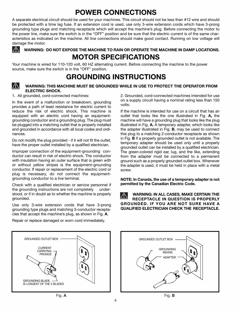
2. Grounded, cord-connected machines intended for useon a supply circuit having a nominal rating less than 150volts:
If the machine is intended for use on a circuit that has anoutlet that looks like the one illustrated in Fig. A, themachine will have a grounding plug that looks like the plugillustrated in Fig. A. A temporary adapter, which looks likethe adapter illustrated in Fig. B, may be used to connectthis plug to a matching 2-conductor receptacle as shownin Fig. B if a properly grounded outlet is not available. Thetemporary adapter should be used only until a properlygrounded outlet can be installed by a qualified electrician.The green-colored rigid ear, lug, and the like, extendingfrom the adapter must be connected to a permanentground such as a properly grounded outlet box. Wheneverthe adapter is used, it must be held in place with a metalscrew.
NOTE: In Canada, the use of a temporary adapter is notpermitted by the Canadian Electric Code.
WARNING: IN ALL CASES, MAKE CERTAIN THE RECEPTACLE IN QUESTION IS PROPERLY
GROUNDED. IF YOU ARE NOT SURE HAVE AQUALIFIED ELECTRICIAN CHECK THE RECEPTACLE.
1. All grounded, cord-connected machines:
In the event of a malfunction or breakdown, groundingprovides a path of least resistance for electric current toreduce the risk of electric shock. This machine isequipped with an electric cord having an equipment-grounding conductor and a grounding plug. The plug mustbe plugged into a matching outlet that is properly installedand grounded in accordance with all local codes and ordi-nances.
Do not modify the plug provided - if it will not fit the outlet,have the proper outlet installed by a qualified electrician.
Improper connection of the equipment-grounding con-ductor can result in risk of electric shock. The conductorwith insulation having an outer surface that is green withor without yellow stripes is the equipment-groundingconductor. If repair or replacement of the electric cord orplug is necessary, do not connect the equipment-grounding conductor to a live terminal.
Check with a qualified electrician or service personnel ifthe grounding instructions are not completely under-stood, or if in doubt as to whether the machine is properlygrounded.
Use only 3-wire extension cords that have 3-pronggrounding type plugs and matching 3-conductor recepta-cles that accept the machine’s plug, as shown in Fig. A.
Repair or replace damaged or worn cord immediately.

5
Use proper extension cords. Make sure your extension cord is in good condition and is a 3-wire extension cord whichhas a 3-prong grounding type plug and matching receptacle which will accept the machine’s plug. When using anextension cord, be sure to use one heavy enough to carry the current of the machine. An undersized cord will causea drop in line voltage, resulting in loss of power and overheating. Fig. D, shows the correct gauge to use dependingon the cord length. If in doubt, use the next heavier gauge. The smaller the gauge number, the heavier the cord.
EXTENSION CORDS
Fig. D
MINIMUM GAUGE EXTENSION CORDRECOMMENDED SIZES FOR USE WITH STATIONARY ELECTRIC MACHINES
Ampere Total Length Gauge ofRating Volts of Cord in Feet Extension Cord
0-6 115 up to 25 18 AWG0-6 115 25-50 16 AWG0-6 115 50-100 16 AWG0-6 115 100-150 14 AWG
6-10 115 up to 25 18 AWG6-10 115 25-50 16 AWG6-10 115 50-100 14 AWG6-10 115 100-150 12 AWG
10-12 115 up to 25 16 AWG10-12 115 25-50 16 AWG10-12 115 50-100 14 AWG10-12 115 100-150 12 AWG
12-16 115 up to 25 14 AWG12-16 115 25-50 12 AWG12-16 115 GREATER THAN 50 FEET NOT RECOMMENDED
OPERATING INSTRUCTIONSFOREWORD
Delta Model 36-225 is a 10" compound miter saw designed to cut wood or aluminum extrusion. Compound angle andbevel cutting are easy and accurate. It can crosscut up to 5-5/8" x 2-3/4", miter at 45° both left and right 4" x 2-3/4",bevel at 45° left 1-5/8" x 5-5/8", and compound 45° x 45°, 4" x 1-5/8". It has Patented trigger-controlled indexing withpositive miter stops at 0°, 15.5°, 22.5°, 30°, and 45° both left and right, and bevel stops at 0° and 45° left.
UNPACKING AND CLEANINGCarefully unpack the machine and all loose items from the shipping container(s). Remove the protective coating fromall unpainted surfaces. This coating may be removed with a soft cloth moistened with kerosene (do not use acetone, gaso-line or lacquer thinner for this purpose). After cleaning, cover the unpainted surfaces with a good quality household floorpaste wax.

6
UNPACKING1. Remove the miter saw and all loose items from thecarton. IMPORTANT: DO NOT LIFT THE MITER SAWBY THE SWITCH HANDLE AS THIS MAY CAUSEMISALIGNMENT. ALWAYS LIFT THE MACHINE BYTHE BASE OR CARRYING HANDLE (see (D) Fig. 4A.Fig. 2 illustrates the machine and all loose items afterthey have been removed from the carton.
1 - Miter Saw
2 - Dust Bag
3 - Wrench for changing the blade
4 - Clamp
5 - Table Extension (2)
Fig. 2
2 4
3
1
ASSEMBLY INSTRUCTIONSWARNING: FOR YOUR OWN SAFETY, DO NOT CONNECT THE MITER SAW TO THE POWERSOURCE UNTIL THE MACHINE IS COMPLETELY ASSEMBLED AND YOU HAVE READ ANDUNDERSTOOD THE ENTIRE OWNER’S MANUAL.
Fig. 3
Fig. 4
MOVING THE CUTTINGHEAD TO THERAISED POSITION1. Push down on handle (A) Fig. 3, to release springpressure. Then pull out cuttinghead lockpin (B) andmove cuttinghead (C) to the raised position.
2. Fig. 4, illustrates the lockpin (B) pulled out and thecuttinghead (C) in the raised position.
Fig. 4A
ASSEMBLING TABLE EXTENSIONSRemove two screws from each extension rods.Assemble ends of table extension (A) Fig. 4A, onto theextension rods (B) as shown. Tighten screws (C) to holdtable extension in place.
5
A
B
C
A
B
C
B
C
D

7
Fig. 5
Fig. 7
Fig. 8
C
AC B
D
Fig. 6
ROTATING TABLE TO THE90° POSITION
Loosen table locking handle (A) Fig. 5, one turn andsqueeze locking trigger (B). Rotate table until plunger (C)is engaged into the 90° stop (0° on scale). Then tightenhandle (A) by turning clockwise.
ASSEMBLING DUST BAGAssemble dust bag (A) Fig. 6, to free end of dust spout(B) as shown.
ASSEMBLING WORK CLAMP
1. The work clamp (A) Fig. 7, can be used on either theright or left side of the saw base. Insert post of workclamp (A) into the hole located on either the right or leftside of the saw base.
WARNING: Keep hands out of path of saw blade.If the workpiece you are cutting would cause your handto be within the hazard zone of the saw blade, the work-piece should be clamped in place before making cut.
IDENTIFICATION LABELThe identification label is located at the rear of the motorhousing as shown at (D) Fig. 8. Record the serial num-ber onto the front cover of this manual for future refer-ence.
A
A
B

8
FASTENING MACHINE TO SUPPORTING SURFACE
Fig. 9
Before operating your compound miter saw, make sure it is firmly mounted to a sturdy workbench or other supportingsurface. Four holes are provided, two of which are shown at (A) Fig. 9, for fastening the saw to a supporting surface.
When frequently moving the saw from place to place, we suggest that the saw be mounted to a 3/4″ piece ofplywood. The saw can then be easily moved from place to place and the plywood clamped to the supportingsurface using “C” clamps.
A
TABLE HAZARD AREAWARNING: THE AREA INSIDE THE TWO RED LINES (A) FIG. 9A, ON THE TABLE IS DESIGNATED AS A HAZARD ZONE. NEVER PLACE YOUR HANDS INSIDE THIS AREA WHILE THE TOOL IS BEING OPERATED.
Fig. 9A
A
A

99
STARTING ANDSTOPPING MACHINETo start the machine, depress switch trigger (A) Fig. 13.To stop the machine, release the switch trigger.Your miter saw is equipped with an automatic electricblade brake. As soon as the switch trigger (A) Fig. 13, isreleased, the electric brake is activated and stops theblade in seconds.
WARNING: A TURNING SAW BLADE CAN BEHAZARDOUS. AFTER COMPLETING CUT, RELEASESWITCH TRIGGER (A) FIG. 13, TO ACTIVATE BLADEBRAKE. KEEP CUTTINGHEAD DOWN UNTIL BLADEHAS COME TO A COMPLETE STOP. THEN RETURNCUTTING-HEAD TO THE RAISED POSITION.
WARNING: THE TORQUE DEVELOPED DURINGBRAKING MAY LOOSEN THE ARBOR SCREW. THEARBOR SCREW SHOULD BE CHECKED PERIODI-CALLY AND TIGHTENED IF NECESSARY.
LOCKING SWITCH INTHE “OFF” POSITION
IMPORTANT: When the machine is not in use, theswitch should be locked in the “OFF” position to pre-vent unauthorized use, using a padlock (B) Fig. 14 witha 3/16" diameter shackle.
ROTATING TABLEFOR MITER CUTTING
Your miter saw will cut any angle from a straight 90° (0°on scale) cut to 47° right and left. Simply loosen lock han-dle (A) Fig. 15, squeeze plunger trigger (B), and move thecontrol arm to the desired angle. THEN TIGHTEN LOCKHANDLE (A).The miter saw is equipped with positive stops at the 0°,15.5°, 22.5°, 30°, and 45° right and left positions. Simplyloosen lock handle (A) Fig. 15, and move the control armuntil the plunger engages into one of the nine positivestops, eight of which are shown at (C). THEN TIGHTENLOCK HANDLE (A). To disengage the positive stop,squeeze plunger trigger (B). If adjustment to the positivestops is necessary, see section titled “ADJUSTINGTABLE POSITIVE STOPS”. In addition, a triangle indi-cator is provided on the miter scale at the 31-5/8° rightand left miter positions for cutting crown moulding. Referto the “CUTTING CROWN MOULDING” section of thismanual.
IMPORTANT: ALWAYS TIGHTEN LOCK HANDLE (A)FIG. 15, BEFORE CUTTING.
Fig. 13
Fig. 14
Fig. 15
OPERATING CONTROLS
A
B
A
BC

10
Fig. 17
Fig. 16
Fig. 18
POINTER AND SCALEA pointer (A) Fig. 16, is supplied which indicates the
actual angle of cut. Each line on the scale (B) represents
1°. In effect, when the pointer is moved from one line to
the next on the scale, the angle of cut is changed by 1°.
TILTING CUTTINGHEADFOR BEVEL CUTTINGThe cuttinghead of your compound miter saw can betilted to cut any bevel angle from a 90° straight cut-off toa 45° left bevel angle by loosening bevel lock handle (A)Fig. 17, tilting cutting arm (B) to the desired angle andtightening lock handle (A).
Positive stops are provided to rapidly position the sawblade at 90° (0° on scale) and 45° to the table. Refer tothe section of this manual titled “ADJUSTING 90° (0° onscale) AND 45° BEVEL STOPS”. The bevel angle of thecutting arm is determined by the position of the pointer(C) Fig. 17, on the scale (D).In addition, a triangle indicator is provided on the bevelscale at the 33-7/8° bevel angle for cutting crownmoulding. Refer to the “CUTTING CROWN MOULD-ING” section of this manual.
LOCKING CUTTINGHEADIN THE DOWN POSITIONWhen transporting the saw, the cuttinghead should
always be locked in the down position. This can be
accomplished by lowering the cutting arm (A) Fig. 18,
and pushing in plunger (B) until other end of plunger (B)
engages with hole in cutting arm. IMPORTANT: NEVER
CARRY THE COMPOUND MITER BOX BY THE
SWITCH HANDLE. THIS MAY CAUSE MISALIGN-
MENT. ALWAYS LIFT THE MACHINE BY THE BASE
OR CARRYING HANDLE (C) FIG. 18.
B
A
C
A
D
B
AC
B

1111111111
Fig. 20
Fig. 21
Fig. 19
A
A
A
REAR SUPPORT/CARRYING HANDLE
A rear support bar (A) Fig. 19, is provided to prevent themiter saw from tipping to the rear when the cuttingheadis returned to the raised position after a cut has beenmade. For maximum support, support bar (A) should bepulled out as far as possible before attempting to per-form a cut.
The support bar (A) also acts as a carrying handle, asshown in Fig. 20, when transporting the saw.
TABLE EXTENSIONSThere are table extensions (A) Fig. 21, on each side ofthe miter saw base to help support long workpieces. Toextend the table extensions, simply grasp and pull out-ward as shown in Fig. 21.
Fig. 22, illustrates table extensions fully extended.
Fig. 22
A
12
Fig. 24
Fig. 25
Fig. 27
Fig. 23
H
G
Fig. 26
ADJUSTMENTS
ADJUSTING TABLEPOSITIVE STOPSDISCONNECT SAW FROM POWER SOURCEBEFORE PERFORMING ANY ADJUSTMENTS.
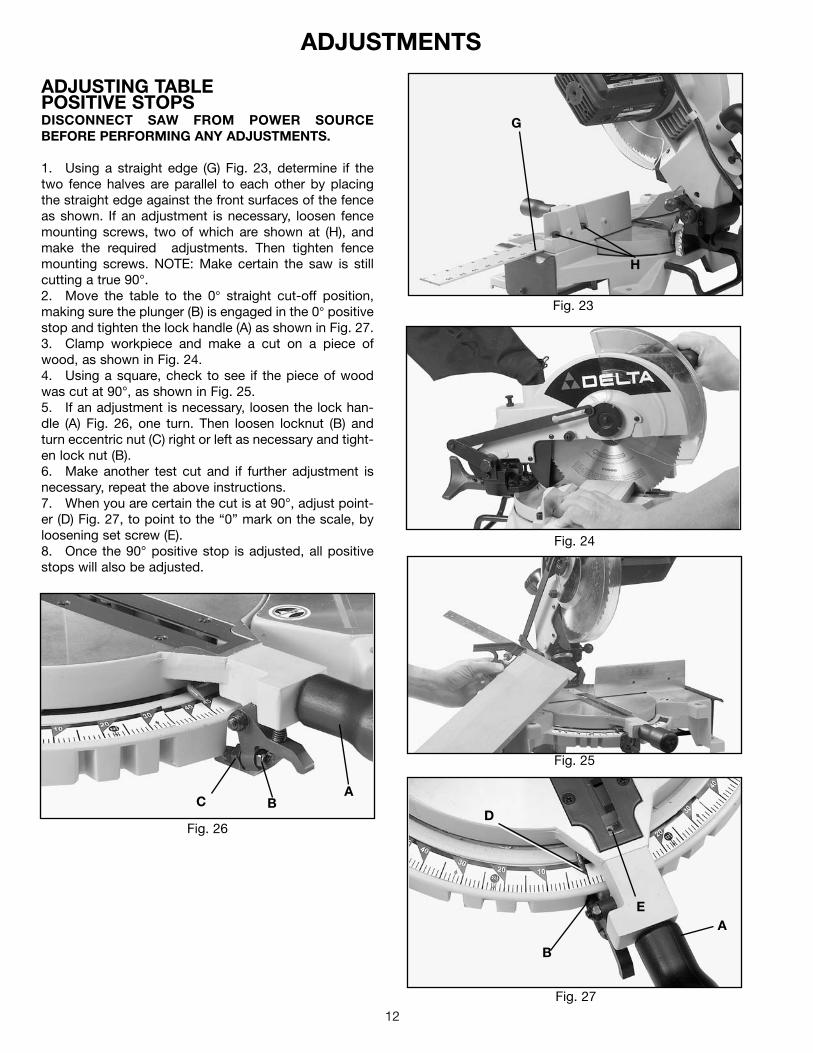
1. Using a straight edge (G) Fig. 23, determine if thetwo fence halves are parallel to each other by placingthe straight edge against the front surfaces of the fenceas shown. If an adjustment is necessary, loosen fencemounting screws, two of which are shown at (H), andmake the required adjustments. Then tighten fencemounting screws. NOTE: Make certain the saw is stillcutting a true 90°.2. Move the table to the 0° straight cut-off position,making sure the plunger (B) is engaged in the 0° positivestop and tighten the lock handle (A) as shown in Fig. 27.3. Clamp workpiece and make a cut on a piece ofwood, as shown in Fig. 24.4. Using a square, check to see if the piece of woodwas cut at 90°, as shown in Fig. 25.5. If an adjustment is necessary, loosen the lock han-dle (A) Fig. 26, one turn. Then loosen locknut (B) andturn eccentric nut (C) right or left as necessary and tight-en lock nut (B).6. Make another test cut and if further adjustment isnecessary, repeat the above instructions.7. When you are certain the cut is at 90°, adjust point-er (D) Fig. 27, to point to the “0” mark on the scale, byloosening set screw (E).8. Once the 90° positive stop is adjusted, all positivestops will also be adjusted.
ABC
D
B
EA

1313131313
Fig. 28
Fig. 29
Fig. 30
Fig. 31
A
CB
D
A
EF
G
B
A
Fig. 32
ADJUSTING DOWNWARDTRAVEL OF SAW BLADE1. DISCONNECT THE SAW FROM THE POWERSOURCE.2. The downward travel of the saw blade can be limit-ed to prevent the saw blade from contacting any metalsurfaces of the machine. This adjustment is made byloosening locknut (A) Fig. 32, and turning adjustingscrew (B) in or out. Then tighten locknut (A).3. When making this adjustment, MAKE SURE THEMACHINE IS DISCONNECTED FROM THE POWERSOURCE and lower the blade as far as possible asshown in Fig. 32. Rotate the blade by hand to make cer-tain the teeth do not contact any metal surfaces andadjust if necessary.
ADJUSTING 90° AND 45°BEVEL STOPS1. DISCONNECT THE SAW FROM THE POWERSOURCE.2. Loosen bevel lock handle (H) Fig. 29, and move thecutting arm all the way to the right, then tighten the bevellock handle.3. Using a square (A) Fig. 28, place one end of thesquare on the table and the other end against the blade.Check to see if the blade is at 90° to the table, as shownin Fig. 28.4. If an adjustment is necessary, loosen locknut (B)Fig. 29, and turn screw (C) until head of screw (C) con-tacts casting (D) when blade is 90° to the table. Thentighten locknut (B).5. Loosen bevel lock handle (H) Fig. 29, and move thecutting arm all the way to the left bevel position andtighten bevel lock handle.6. Using a combination square (A) Fig. 30, check to seeif the blade is at 45° to the table, as shown.7. If an adjustment is necessary, loosen locknut (E)Fig. 31, and turn screw (F) until screw (F) contacts cast-ing (G) when blade is 45° to the table. Then tighten lock-nut (E).8. These positive stops enable you to rapidly positionthe blade at the 90° (0° on scale) and 45° bevel angle tothe table.
H

14
Fig. 33
TYPICAL OPERATIONS AND HELPFUL HINTS
Fig. 35
A
A
B
Fig. 34
1. Before cutting, make certain the cutting arm andtable are at their correct settings and firmly locked inplace.2. Before cutting, determine that the saw is the rightsize for the workpiece.3. Place the workpiece on the table and clamp it firm-ly against the fence. Fig. 35, illustrates the standardequipment work clamp (A) being used to clamp a work-piece to the fence. The clamp (A) can also be used onthe right side of the machine.4. For best results cut at a slow, even cutting rate.5. WARNING: If the workpiece you are cuttingwould cause your hand to be within the hazard zone ofthe saw blade, the workpiece should be clamped inplace before making cut. See Fig. 35.6. Never attempt any freehand cutting (wood that isnot held firmly against the fence and table).
ADJUSTING BLADEPARALLEL TO TABLE SLOT1. DISCONNECT THE SAW FROM THE POWERSOURCE.
2. Lower the cutting arm. The saw blade (A) Fig. 33,should be parallel to the left edge (B) of the table open-ing.
3. If an adjustment is necessary, raise the cuttinghead,loosen screws (C) Fig. 34, and move the cutting arm untilthe blade is parallel with the left edge (B) Fig. 33 of thetable opening. Then tighten the two screws (C) Fig. 34.
4. Check miter angles and readjust as necessary.
C

1515151515
Fig. 37Fig. 36
Fig. 38Fig. 39
AUXILIARY WOOD FENCEWhen performing multiple or repetitive cut-off operations that result in small cut-off pieces, one inch or less, it is pos-sible for the saw blade to catch the cut-off pieces and project them out of the machine or into the blade guard andhousing, possibly causing damage or injury. In order to limit the possibility of personal injury or blade guard damage,an axuiliary wood fence can be mounted to your saw as follows:Holes are provided in the fence to attach an auxiliary fence (A) Fig. 36. This auxiliary fence is constructed of straightwood approximately 1/2 inch thick by 3 inches high by 18 inches long. NOTE: The auxiliary fence (A) is used ONLY withthe saw blade in the 0° bevel position (90° to the table). When bevel cutting (blade tilted) the auxiliary fence will haveto be removed.
GENERAL CUTTING OPERATIONS1. Your compound miter saw has the capacity to cut standard 2 x 6’s at the straight 90° cut-off position, as shown inFig. 37.2. A standard 2 x 4 can be mitered at 45° cut-off position at 90° or 45° bevel positions as shown in Fig. 38.3. Cutting a standard 4 x 4 at 90° is easily accomplished with your compound miter box, as shown in Fig. 39.
AA

16
Fig. 40
Fig. 41
CUTTING ALUMINUMAluminum extrusions such as used for making aluminumscreens and storm windows can easily be cut with yourcompound miter saw. When cutting aluminum extrusions,or other sections that can be cut with a saw blade and arewithin the capacity of the machine, position the materialso the blade is cutting through the smallest cross-section, as shown in Fig. 40. The wrong way to cutaluminum angles is illustrated in Fig. 41. Be sure to applya stick wax (similar to Johnson’s stick wax #140) to theblade before cutting any aluminum stock. This stick waxis available at most industrial mill supply houses. Thestick wax provides proper lubrication and keeps chipsfrom adhering to the blade.
WARNING: NEVER APPLY LUBRICANT TO THEBLADE WHILE THE MACHINE IS RUNNING.
FENCE BLADE
WRONG
FENCEBLADE
RIGHT
CUTTING BOWED MATERIALWhen cutting flat pieces, first check to see if the material is bowed. If it is, make sure the materialis positioned on the table as shown in Fig. 42.
If the material is positioned the wrong way, as shown in Fig. 43, the workpiece will pinch the bladenear the completion of the cut.
Fig. 42
Fig. 43
RIGHT
WRONG

1717171717
Fig. 44
Fig. 45
Fig. 46
Fig. 47
C
D
C A
DB
CUTTINGCROWN MOULDINGOne of the many features of your saw is the ease of cut-ting crown moulding. The following is an example of cut-ting both inside and outside corners on 52/38° wallangle crown moulding. NOTE: When cutting 45° wallangle crown moulding the following procedure for insideand outside corners is the same with the exception thatthe bevel position will always be at 30° and the miterposition will be 35-1/4° to the right or left.1. Move the table to the 31-5/8° right miter position andlock the table in position. NOTE: A triangle indicator isprovided on the miter scale to find this angle quickly.2. Tilt the saw blade to the 33-7/8° left bevel positionand tighten bevel lock handle. NOTE: A triangle indica-tor is provided on the bevel scale to find this anglequickly.3. Place the crown moulding on the table with theCEILING EDGE of the moulding against the fence, andmake the cut, as shown in Fig. 44. NOTE: The piece ofcrown moulding used for the outside corner will alwaysbe on the right hand side of the blade, as shown at (A)Fig. 44. The piece of crown moulding used for the insidecorner will always be on the left hand side of the blade,as shown at (B) Fig. 44.4. To make the matching halves of the inside and outsidecorners simply rotate the table to the 31-5/8° left miterposition and tighten table lock handle. NOTE: A triangleindicator is provided on the miter scale to find this anglequickly.5. Place the crown moulding on the table with the WALLEDGE of the crown moulding against the fence asshown in Fig. 45, then make the cut. Again, the piece ofcrown moulding used for the outside corner will alwaysbe on the right side of the blade, as shown at (C) Fig. 45.The piece of crown moulding used for the inside cornerwill always be on the left side of the blade, as shown at(D) Fig. 45.6. Fig. 46, illustrates the two outside corner pieces;(A) being the piece cut at (A) Fig. 44, and (C) being thepiece cut at (C) Fig. 45.7. Fig. 47, illustrates the two inside corner pieces;(B) being the piece cut at (B) Fig. 44, and (D) being thepiece cut at (D) Fig. 45.
B A

18
CHANGING THE BLADEWARNING: USE ONLY CROSS-CUTTING SAW
BLADES. USE ONLY 10" DIAMETER SAW BLADESRATED FOR 6000 RPM OR HIGHER WITH 5/8"ARBOR HOLES.1. DISCONNECT THE MACHINE FROM THEPOWER SOURCE.2. Remove screw (A) Fig. 49.
Fig. 48
CONSTRUCTING WORK SUPPORT EXTENSIONSOne of the unique features of your miter saw is the ease with which you can construct work supports. Fig. 48, illus-trates the miter saw mounted to two standard 2 x 4’s (A). Fasten the grooves in the four mounting legs, two of whichare shown at (B), to the 2 x 4’s using four screws through the four holes in the mounting legs. The length of the 2 x 4’s(A) can vary depending on your preference. The distance from the top of the 2 x 4’s (A) to the compound miter sawtable is 3-1/2 inches. This enables you to fasten standard 2 x 4’s (C) to the top of the 2 x 4’s (A), as shown. The top ofthe 2 x 4’s (C) will then be the same height as the miter saw table. This method allows you to provide support for longwork-pieces using standard 2 x 4’s instead of constructing an expensive, complicated work support.
MAINTENANCE
C
C
A
B
Fig. 49
A

1919191919
Fig. 50
Fig. 51
Fig. 52
D
CE
F
Fig. 53
3. Rotate arbor cover (B) Fig. 50, and lower guard (G)to the rear, exposing arbor screw (C), as shown.
4. Remove arbor screw (C) Fig. 50, by turning screwclockwise with wrench supplied while at the same timepressing in on arbor lock (D) Fig. 51, to keep the arborfrom turning. Remove outside blade flange (E) Fig. 50,and saw blade (F). DO NOT REMOVE INSIDE BLADEFLANGE.
5. Assemble new saw blade MAKING CERTAINTEETH OF SAW BLADE ARE POINTING DOWN ATTHE FRONT, AS SHOWN and assemble outside bladeflange (E)Fig. 50, making sure flats on outside blade flange areengaged with flats on arbor shaft.
6. Thread arbor screw (C) Fig. 50, into saw arbor byturning screw (C) counterclockwise as far as possible byhand. Then tighten arbor screw (C) with wrench suppliedwhile at the same time pressing in on arbor lock (D) Fig.51, to keep arbor from turning.
7. Rotate arbor cover (B) Fig. 50, and lower guard (G)to the front and replace screw that was removed inSTEP 2 and securely tighten.
BRUSH INSPECTIONAND REPLACEMENTCAUTION: BEFORE INSPECTING BRUSHES, DIS-CONNECT THE MACHINE FROM THE POWERSOURCE.
Brush life varies. It depends on the load on the motor.Check the brushes after the first 50 hours of use for anew machine or after a new set of brushes has beeninstalled.
After the first check, examine them after about 10 hoursof use until such time that replacement is necessary.
The brush holders (A) Fig. 52, are located on the motorhousing opposite each other. Fig. 53, illustrates one ofthe brushes removed for inspection. When the carbonon either brush is worn to 3/16" in length or if eitherspring or shunt wire is burned or damaged in any way,replace both brushes. If the brushes are found service-able after removing, reinstall them in the same positionas removed.
A
B
G
E
C
F

20
Two Year Limited WarrantyDelta will repair or replace, at its expense and at its option, any Delta machine, machine part, or machine accessory whichin normal use has proven to be defective in workmanship or material, provided that the customer returns the product pre-paid to a Delta factory service center or authorized service station with proof of purchase of the product within two yearsand provides Delta with reasonable opportunity to verify the alleged defect by inspection. Delta may require that electricmotors be returned prepaid to a motor manufacturer’s authorized station for inspection and repair or replacement. Deltawill not be responsible for any asserted defect which has resulted from normal wear, misuse, abuse or repair or alterationmade or specifically authorized by anyone other than an authorized Delta service facility or representative. Under no cir-cumstances will Delta be liable for incidental or consequential damages resulting from defective products. This warrantyis Delta’s sole warranty and sets forth the customer’s exclusive remedy, with respect to defective products; all other war-ranties, express or implied, whether of merchantability, fitness for purpose, or otherwise, are expressly disclaimed by Delta.
PARTS, SERVICE OR WARRANTY ASSISTANCEAll Delta Machines and accessories are manufactured to high quality standards and are serviced by a networkof Porter-Cable • Delta Factory Service Centers and Delta Authorized Service Stations. To obtain additionalinformation regarding your Delta quality product or to obtain parts, service, warranty assistance, or the loca-tion of the nearest service outlet, please call 1-800-223-7278 (In Canada call 1-800-463-3582).
ACCESSORIESA complete line of accessories is available from your Delta Supplier, Porter-Cable • Delta Factory Service Centers,and Delta Authorized Service Stations. Please visit our Web Site www.deltamachinery.com for a catalog orfor the name of your nearest supplier.
WARNING: Since accessories other than those offered by Delta have not been tested with this product, use of such accessories could be hazardous. For safest operation, only Delta recommended accessories should be used with this product.

The following are trademarks of PORTER-CABLE·DELTA (Las siguientes son marcas registradas de PORTER-CABLE S.A.): BAMMER®,INNOVATION THAT WORKS®, JETSTREAM®, LASERLOC®, OMNIJIG®, POCKET CUTTER®, PORTA-BAND®, PORTA-PLANE®, PORTER-CABLE®, QUICKSAND®, SANDTRAP®, SAW BOSS®, SPEED-BLOC®, SPEEDMATIC®, SPEEDTRONIC®, STAIR-EASE®, THE PROFESSION-AL EDGE®, THE PROFESSIONAL SELECT®, TIGER CUB®, TIGER SAW®, TORQBUSTER®, WHISPER SERIES®, DURATRONIC™, FLEX™,FRAME SAW™, MICRO-SET™, MORTEN™, NETWORK™, RIPTIDE™, TRU-MATCH™, WOODWORKER’S CHOICE™, THE AMERICANWOOD SHOP™ (design) , AUTO-SET™, B.O.S.S.™, BUILDER’S SAW™, CONTRACTOR’S SAW™, DELTA™, DELTACRAFT™, HOME-CRAFT™, JET-LOCK™, KICKSTAND™, THE LUMBER COMPANY™ (design). MICRO-SET™, Q3™, QUICKSET II™, QUICKSET PLUS™,SAFEGUARD II™, SANDING CENTER™, SIDEKICK™, UNIFENCE™, UNIGUARD™, UNIRIP™, UNISAW™, VERSA-FEEDER™ , THIN-LINE™, TPS™, Emc²™.
Trademarks noted with ™ and ® are registered in the United States Patent and Trademark Office and may also be registered in other coun-tries. Las Marcas Registradas con el signo de ™ y ® son registradas por la Oficina de Registros y Patentes de los Estados Unidos y tam-bién pueden estar registradas en otros países.
PORTER-CABLE • DELTA SERVICE CENTERS(CENTROS DE SERVICIO DE PORTER-CABLE • DELTA)
Parts and Repair Service for Porter-Cable • Delta Machinery are Available at These Locations(Obtenga Refaccion de Partes o Servicio para su Herramienta en los Siguientes Centros de Porter-Cable • Delta)
Authorized Service Stations are located in many large cities. Telephone 800-438-2486 or 731-541-6042 for assistance locating one.Parts and accessories for Porter-Cable ·Delta products should be obtained by contacting any Porter-Cable·Delta Distributor, AuthorizedService Center, or Porter-Cable·Delta Factory Service Center. If you do not have access to any of these, call 800-223-7278 and you willbe directed to the nearest Porter-Cable·Delta Factory Service Center. Las Estaciones de Servicio Autorizadas están ubicadas en muchasgrandes ciudades. Llame al 800-438-2486 ó al 731-541-6042 para obtener asistencia a fin de localizar una. Las piezas y los accesoriospara los productos Porter-Cable·Delta deben obtenerse poniéndose en contacto con cualquier distribuidor Porter-Cable·Delta, Centrode Servicio Autorizado o Centro de Servicio de Fábrica Porter-Cable·Delta. Si no tiene acceso a ninguna de estas opciones, llame al800-223-7278 y le dirigirán al Centro de Servicio de Fábrica Porter-Cable·Delta más cercano.
ARIZONATempe 85282 (Phoenix)2400 West Southern AvenueSuite 105Phone: (602) 437-1200Fax: (602) 437-2200
CALIFORNIAOntario 91761 (Los Angeles)3949A East Guasti RoadPhone: (909) 390-5555Fax: (909) 390-5554San Leandro 94577 (Oakland)3039 Teagarden StreetPhone: (510) 357-9762Fax: (510) 357-7939
FLORIDADavie 33314 (Miami)4343 South State Rd. 7 (441)Unit #107Phone: (954) 321-6635Fax: (954) 321-6638
Tampa 33609 4538 W. Kennedy BoulevardPhone: (813) 877-9585Fax: (813) 289-7948
GEORGIAForest Park 30297 (Atlanta)5442 Frontage Road,Suite 112Phone: (404) 608-0006Fax: (404) 608-1123
ILLINOISAddison 60101 (Chicago)311 Laura DrivePhone: (630) 628-6100Fax: (630) 628-0023
Woodridge 60517 (Chicago)2033 West 75th StreetPhone: (630) 910-9200Fax: (630) 910-0360
MARYLANDElkridge 21075 (Baltimore)7397-102 Washington Blvd.Phone: (410) 799-9394Fax: (410) 799-9398
MASSACHUSETTSBraintree 02185 (Boston)719 Granite StreetPhone: (781) 848-9810Fax: (781) 848-6759Franklin 02038 (Boston)Franklin Industrial Park101E Constitution Blvd.Phone: (508) 520-8802Fax: (508) 528-8089
MICHIGANMadison Heights 48071 (Detroit)30475 Stephenson HighwayPhone: (248) 597-5000Fax: (248) 597-5004
MINNESOTAMinneapolis 554295522 Lakeland Avenue NorthPhone: (763) 561-9080Fax: (763) 561-0653
MISSOURINorth Kansas City 641161141 Swift AvenueP.O. Box 12393Phone: (816) 221-2070Fax: (816) 221-2897
St. Louis 631197574 Watson RoadPhone: (314) 968-8950Fax: (314) 968-2790
NEW YORKFlushing 11365-1595 (N.Y.C.)175-25 Horace Harding Expwy.Phone: (718) 225-2040Fax: (718) 423-9619
NORTH CAROLINACharlotte 282709129 Monroe Road, Suite 115Phone: (704) 841-1176Fax: (704) 708-4625
OHIOColumbus 432144560 Indianola AvenuePhone: (614) 263-0929Fax: (614) 263-1238
Cleveland 441258001 Sweet Valley DriveUnit #19Phone: (216) 447-9030Fax: (216) 447-3097
OREGONPortland 972304916 NE 122 nd Ave.Phone: (503) 252-0107Fax: (503) 252-2123
PENNSYLVANIAWillow Grove 19090520 North York RoadPhone: (215) 658-1430Fax: (215) 658-1433
TEXASCarrollton 75006 (Dallas)1300 Interstate 35 N, Suite 112Phone: (972) 446-2996Fax: (972) 446-8157
Houston 77055West 10 Business Center1008 Wirt Road, Suite 120Phone: (713) 682-0334Fax: (713) 682-4867
WASHINGTONAuburn 98001(Seattle)3320 West Valley HWY, NorthBuilding D, Suite 111Phone: (253) 333-8353Fax: (253) 333-9613
Printed in U.S.A.
CANADIAN PORTER-CABLE • DELTA SERVICE CENTERSALBERTABay 6, 2520-23rd St. N.E.Calgary, AlbertaT2E 8L2Phone: (403) 735-6166Fax: (403) 735-6144
BRITISH COLUMBIA8520 Baxter PlaceBurnaby, B.C.V5A 4T8Phone: (604) 420-0102Fax: (604) 420-3522
MANITOBA1699 Dublin AvenueWinnipeg, ManitobaR3H 0H2Phone: (204) 633-9259Fax: (204) 632-1976
ONTARIO505 Southgate DriveGuelph, OntarioN1H 6M7Phone: (519) 836-2840Fax: (519) 767-4131
QUÉBEC1515 ave.St-Jean Baptiste,Québec, QuébecG2E 5E2Phone: (418) 877-7112Fax: (418) 877-7123
1447, BeginSt-Laurent, (Montréal),QuébecH4R 1V8Phone: (514) 336-8772Fax: (514) 336-3505