1 verilog digital system design z. navabi, 2006 digital design flow digital design flow begins with...
TRANSCRIPT

1Verilog Digital System Design Z. Navabi, 2006
Digital Design FlowDigital Design Flow
Digital Design Flow begins with specification of the Digital Design Flow begins with specification of the design at various levels of abstraction.design at various levels of abstraction.
Design entry phase:Design entry phase: Specification of design as a Specification of design as a mixture of behavioralmixture of behavioralVerilog code, instantiation of Verilog modules, and Verilog code, instantiation of Verilog modules, and bus and wire assignmentsbus and wire assignments

2Verilog Digital System Design Z. Navabi, 2006
Digital Design FlowDigital Design Flow
FPLD Design FlowFPLD Design Flow
Compilation and SynthesisAnalysis Synthesis Routing and placement
Y = a & d & ww = a & b | c
Post-synthesis Simulation
Timing Analysis
1.6 ns2 ns
C++ Classes, Language Representation
Behavioral Simulation Assertion Verification Formal Verification
Violation Report;Time of Violation;Monitor Coverage
Pass / Fail ReportProperty CoverageCounter Examples
Design Entry in Verilogalways (posedge clk) begin . . . end
if (…) bus = w;else . . .
Comp1 U1 (. . .);Comp2 U2 (. . .);. . .Compn Un (. . .);
module design (. . .); assign . . . always . . . compi (. . .)endmodule
Testbench in Verilog
module testbench (); generate data; process data;endmodule
Device Programming ASIC Netlist Custom IC Layout
EDIFor other netlists1010...

3Verilog Digital System Design Z. Navabi, 2006
Digital Design FlowDigital Design Flow
FPLD Design FlowFPLD Design Flow
Behavioral Simulation Assertion Verification Formal Verification
Violation Report;Time of Violation;Monitor Coverage
Pass / Fail ReportProperty CoverageCounter Examples
Design Entry in Verilogalways (posedge clk) begin . . . end
if (…) bus = w;else . . .
Comp1 U1 (. . .);Comp2 U2 (. . .);. . .Compn Un (. . .);
module design (. . .); assign . . . always . . . compi (. . .)endmodule
Testbench in Verilog
module testbench (); generate data; process data;endmodule
Design Design EntryEntryPhasePhase

4Verilog Digital System Design Z. Navabi, 2006
Digital Design FlowDigital Design Flow
Presynthesis verification:Presynthesis verification: Generating testbenches for Generating testbenches for verification of the design and later for verifying the verification of the design and later for verifying the synthesis outputsynthesis output

5Verilog Digital System Design Z. Navabi, 2006
Compilation and SynthesisAnalysis Synthesis Routing and placement
Y = a & d & ww = a & b | c
Timing Analysis
1.6 ns2 ns
C++ Classes, Language Representation
Behavioral Simulation Assertion Verification Formal Verification
Violation Report;Time of Violation;Monitor Coverage
Pass / Fail ReportProperty CoverageCounter Examples
Digital Design FlowDigital Design Flow
FPLD Design Flow FPLD Design Flow (Continued)(Continued)
PresynthesisPresynthesisVerificationVerification

6Verilog Digital System Design Z. Navabi, 2006
Digital Design FlowDigital Design Flow
Synthesis process:Synthesis process: Translating the design into actual Translating the design into actual hardware of a target device (FPLD, ASIC or custom hardware of a target device (FPLD, ASIC or custom IC)IC)

7Verilog Digital System Design Z. Navabi, 2006
Compilation and SynthesisAnalysis Synthesis Routing and placement
Y = a & d & ww = a & b | c
Timing Analysis
1.6 ns2 ns
C++ Classes, Language Representation
Behavioral Simulation Assertion Verification Formal Verification
Violation Report;Time of Violation;Monitor Coverage
Pass / Fail ReportProperty CoverageCounter Examples
Digital Design FlowDigital Design Flow
FPLD Design Flow FPLD Design Flow (Continued)(Continued)
Synthesis Synthesis ProcessProcess

8Verilog Digital System Design Z. Navabi, 2006
Digital Design FlowDigital Design Flow
Postsynthesis simulation:Postsynthesis simulation: Testing the behavioral Testing the behavioral model of the design and its hardware model by using model of the design and its hardware model by using presynthesis test datapresynthesis test data

9Verilog Digital System Design Z. Navabi, 2006
Digital Design FlowDigital Design Flow
FPLD Design Flow (Continued)FPLD Design Flow (Continued)
Post-synthesis Simulation
Timing Analysis
1.6 ns2 ns
Testbench in Verilog
module testbench (); generate data; process data;endmodule
Device Programming ASIC Netlist Custom IC Layout
EDIFor other netlists1010...
PostsynthesiPostsynthesiss
VerificationVerification

10Verilog Digital System Design Z. Navabi, 2006
Digital Design FlowDigital Design Flow
Digital Design Flow ends with generating netlist for Digital Design Flow ends with generating netlist for an application specific integrated circuits (ASIC), an application specific integrated circuits (ASIC), layout for a custom IC, or a program for a layout for a custom IC, or a program for a programmable logic devices (PLD)programmable logic devices (PLD)

11Verilog Digital System Design Z. Navabi, 2006
Digital Design FlowDigital Design Flow
FPLD Design Flow (Continued)FPLD Design Flow (Continued)
Post-synthesis Simulation
Timing Analysis
1.6 ns2 ns
Testbench in Verilog
module testbench (); generate data; process data;endmodule
Device Programming ASIC Netlist Custom IC Layout
EDIFor other netlists1010...

12Verilog Digital System Design Navabi, 2006
Digital DesignDigital Design
FlowFlow
HardwareHardware
GenerationGeneration
Design EntryDesign Entry Testbench in VerilogTestbench in Verilog
Design ValidationDesign ValidationCompilationCompilation
and Synthesisand Synthesis
PostsynthesisPostsynthesis
SimulationSimulationTimingTiming
AnalysisAnalysis
Digital Design FlowDigital Design Flow

13Verilog Digital System Design Z. Navabi, 2006
Verilog HDLVerilog HDL
A language that can be understood by:A language that can be understood by: System Designers System Designers RT Level Designers, RT Level Designers, Test Engineers Test Engineers Simulators Simulators Synthesis ToolsSynthesis Tools Machines Machines
Has become an IEEE standardHas become an IEEE standard

14Verilog Digital System Design Z. Navabi, 2006
The Verilog LanguageThe Verilog Language The Verilog HDL satisfies all requirements for design The Verilog HDL satisfies all requirements for design
and synthesis of digital systems:and synthesis of digital systems:
Supports hierarchical description of hardware Supports hierarchical description of hardware from system to gate or even switch level. from system to gate or even switch level.
Has strong support at all levels for timing Has strong support at all levels for timing specification and violation detection. specification and violation detection.
A hardware component is described by the A hardware component is described by the module_declaration module_declaration language construct in it. language construct in it.

15Verilog Digital System Design Z. Navabi, 2006
The Verilog LanguageThe Verilog Language The Verilog HDL satisfies all requirements for design The Verilog HDL satisfies all requirements for design
and synthesis of digital systems (Continued):and synthesis of digital systems (Continued):
Description of a module specifies a component’s Description of a module specifies a component’s input and output list as well as internal input and output list as well as internal component busses and registers within a component busses and registers within a modulemodule, , concurrent assignments, component concurrent assignments, component instantiations, and procedural blocks can be used instantiations, and procedural blocks can be used to describe a hardware component.to describe a hardware component.
Several modules can hierarchically be instantiated Several modules can hierarchically be instantiated to form other hardware structure. to form other hardware structure.
Simulation environments provide graphical front-Simulation environments provide graphical front-end programs and waveform editing and display end programs and waveform editing and display tools. tools.
Synthesis tools are based on a subset of Verilog. Synthesis tools are based on a subset of Verilog.

16Verilog Digital System Design Z. Navabi, 2006
Elements of VerilogElements of Verilog
We discuss basic constructs of Verilog language for We discuss basic constructs of Verilog language for describing a hardware module.describing a hardware module.

17Verilog Digital System Design Z. Navabi, 2006
Elements of VerilogElements of VerilogHardware Hardware Modules Modules
Primitive Primitive InstantiationsInstantiations
Assign Assign Statements Statements
Condition Condition ExpressionExpression
Procedural Procedural BlocksBlocks
Module Module InstantiationsInstantiations

18Verilog Digital System Design Z. Navabi, 2006
Hardware ModulesHardware ModulesHardware Hardware Modules Modules
Primitive Primitive InstantiationsInstantiations
Assign Assign Statements Statements
Condition Condition ExpressionExpression
Procedural Procedural BlocksBlocks
Module Module InstantiationsInstantiations
Hardware Modules

19Verilog Digital System Design Z. Navabi, 2006
Hardware ModulesHardware Modules
modulemodule module-name module-name List of ports;List of ports;DeclarationsDeclarations......Functional specification of moduleFunctional specification of module......
endmoduleendmodule
Module SpecificationsModule Specifications
KeyworKeyword d
modulemodule
module :module :The Main The Main ComponeCompone
nt of nt of VerilogVerilog
Keyword Keyword endmodendmod
uleule
Variables, Variables, wires, and wires, and
module module parametersparameters
are declared.are declared.

20Verilog Digital System Design Z. Navabi, 2006
Hardware ModulesHardware Modules
There is more than one way to describe a Module in There is more than one way to describe a Module in Verilog.Verilog.
May correspond to descriptions at various levels of May correspond to descriptions at various levels of abstraction or to various levels of detail of the abstraction or to various levels of detail of the functionality of a module. functionality of a module.
We show a small example and several alternative ways We show a small example and several alternative ways to describe it in Verilog.to describe it in Verilog.

21Verilog Digital System Design Z. Navabi, 2006
Primitive InstantiationsPrimitive InstantiationsHardware Hardware Modules Modules
Primitive Primitive InstantiationsInstantiations
Assign Assign Statements Statements
Condition Condition ExpressionExpression
Procedural Procedural BlocksBlocks
Module Module InstantiationsInstantiations
PrimitiveInstantiations

22Verilog Digital System Design Z. Navabi, 2006
Primitive InstantiationsPrimitive Instantiations
a
s
b
s_bar
a_sel
b_sel
w
A Multiplexer Using Basic Logic GatesA Multiplexer Using Basic Logic Gates
Logic Logic GatesGatescalledcalled
PrimitivePrimitivess

23Verilog Digital System Design Z. Navabi, 2006
Primitive InstantiationsPrimitive Instantiations
modulemodule MultiplexerA ( MultiplexerA (inputinput a, b, s, a, b, s, output output w);w);wirewire a_sel, b_sel, s_bar; a_sel, b_sel, s_bar;notnot U1 (s_bar, s); U1 (s_bar, s);andand U2 (a_sel, a, s_bar); U2 (a_sel, a, s_bar);andand U3 (b_sel, b, s); U3 (b_sel, b, s);oror U4 (w, a_sel, b_sel); U4 (w, a_sel, b_sel);
endmoduleendmodule
Primitive InstantiationsPrimitive Instantiations
InstantiatioInstantiationnof of
PrimitivesPrimitives

24Verilog Digital System Design Z. Navabi, 2006
Assign StatementsAssign StatementsHardware Hardware Modules Modules
Primitive Primitive InstantiationsInstantiations
Assign Assign Statements Statements
Condition Condition ExpressionExpression
Procedural Procedural BlocksBlocks
Module Module InstantiationsInstantiations
AssignStatements

25Verilog Digital System Design Z. Navabi, 2006
Assign StatementsAssign Statements
modulemodule MultiplexerB ( MultiplexerB (inputinput a, b, s, a, b, s, output output w);w);
assignassign w = (a & ~s) | (b & s); w = (a & ~s) | (b & s);
endmoduleendmodule
Assign Statement and BooleanAssign Statement and Boolean
Continuously Continuously drives drives w w with with
the the right hand right hand
side side expressionexpression
Using Using Boolean Boolean
expressions expressions to describe to describe the logicthe logic

26Verilog Digital System Design Z. Navabi, 2006
Condition ExpressionCondition ExpressionHardware Hardware Modules Modules
Primitive Primitive InstantiationsInstantiations
Assign Assign Statements Statements
Condition Condition ExpressionExpression
Procedural Procedural BlocksBlocks
Module Module InstantiationsInstantiations
ConditionExpression

27Verilog Digital System Design Z. Navabi, 2006
Condition ExpressionCondition Expression
modulemodule MultiplexerC ( MultiplexerC (inputinput a, b, s, a, b, s, output output w);w);assignassign w = s ? b : a; w = s ? b : a;
endmoduleendmodule
Assign Statement and Condition OperatorAssign Statement and Condition Operator
Can be used Can be used when the when the
operation of a operation of a unit is too unit is too
complex to be complex to be described by described by
Boolean Boolean expressionsexpressions
Very Effective Very Effective in describing in describing
complex complex functionalities functionalities
Useful in Useful in describing a describing a
behavior in a behavior in a very compact very compact
wayway

28Verilog Digital System Design Z. Navabi, 2006
Procedural BlocksProcedural BlocksHardware Hardware Modules Modules
Primitive Primitive InstantiationsInstantiations
Assign Assign Statements Statements
Condition Condition ExpressionExpression
Procedural Procedural BlocksBlocks
Module Module InstantiationsInstantiations
ProceduralBlocks

29Verilog Digital System Design Z. Navabi, 2006
Procedural BlocksProcedural Blocks
modulemodule MultiplexerD ( MultiplexerD (input input a, b, s,a, b, s, output output w); w);regreg w; w;alwaysalways @(a, b, s) @(a, b, s) beginbegin
ifif (s) w = b; (s) w = b;elseelse w = a; w = a;
endendendmoduleendmodule
Procedural StatementProcedural Statement
always always statemestateme
ntnt
if-else if-else statemenstatemen
tt
Can be used when Can be used when the operation of a the operation of a
unit is too unit is too complex to be complex to be described by described by Boolean or Boolean or conditional conditional expressionsexpressions
Sensitivity Sensitivity listlist

30Verilog Digital System Design Z. Navabi, 2006
Module InstantiationsModule InstantiationsHardware Hardware Modules Modules
Primitive Primitive InstantiationsInstantiations
Assign Assign Statements Statements
Condition Condition ExpressionExpression
Procedural Procedural BlocksBlocks
Module Module InstantiationsInstantiations
ModuleInstantiations

31Verilog Digital System Design Z. Navabi, 2006
Module InstantiationsModule Instantiations
modulemodule ANDOR ( ANDOR (inputinput i1, i2, i3, i4, i1, i2, i3, i4, outputoutput y); y);assignassign y = (i1 & i2) | (i3 & i4); y = (i1 & i2) | (i3 & i4);
endmoduleendmodule////modulemodule MultiplexerE ( MultiplexerE (inputinput a, b, s, a, b, s, output output w); w);
wirewire s_bar; s_bar;notnot U1 (s_bar, s); U1 (s_bar, s);ANDOR U2 (a, s_bar, s, b, w);ANDOR U2 (a, s_bar, s, b, w);
endmoduleendmodule
Module InstantiationModule Instantiation
ANDOR ANDOR module is module is defineddefined
ANDOR ANDOR module ismodule is
instantiatedinstantiated

32Verilog Digital System Design Z. Navabi, 2006
Module InstantiationsModule Instantiations
Multiplexer Using ANDORMultiplexer Using ANDOR
i1i2
i3i4
y w
ANDORa
s
b

33Verilog Digital System Design Z. Navabi, 2006
Component Description Component Description in Verilogin Verilog
ComponentComponentDescriptionDescription
DataDataComponentsComponents ControllersControllers

34Verilog Digital System Design Z. Navabi, 2006
Data ComponentsData Components
ComponentComponentDescriptionDescription
DataDataComponentsComponents ControllersControllers
DataComponents

35Verilog Digital System Design Z. Navabi, 2006
DataData ComponentsComponents
MultiplexerMultiplexer Flip-FlopFlip-Flop
CounterCounter Full-AdderFull-Adder
Shift-RegisterShift-Register ALUALU
InterconnectionsInterconnections
Data ComponentsData Components

36Verilog Digital System Design Z. Navabi, 2006
DataData ComponentsComponents
MultiplexerMultiplexer Flip-FlopFlip-Flop
CounterCounter Full-AdderFull-Adder
Shift-RegisterShift-Register ALUALU
InterconnectionsInterconnections
MultiplexerMultiplexer
Multiplexer

37Verilog Digital System Design Z. Navabi, 2006
MultiplexerMultiplexer
`timescale`timescale 1ns/100ps 1ns/100ps
modulemodule Mux8 ( Mux8 (inputinput sel, sel, inputinput [7:0] data1, data0, [7:0] data1, data0, outputoutput [7:0] bus1); [7:0] bus1);assignassign #6 bus1 = sel ? data1 : data0; #6 bus1 = sel ? data1 : data0;
endmoduleendmodule
Octal 2-to-1 MUXOctal 2-to-1 MUX Selects its 8-bitSelects its 8-bitdata0data0 or or data1data1
input depending input depending on its on its
selsel input. input.
Defines a Time Unit of Defines a Time Unit of 1 ns and Time 1 ns and Time
Precision of 100 ps.Precision of 100 ps.
A 6-ns DelayA 6-ns Delayis specified for is specified for
all values all values assigned to assigned to
bus1bus1

38Verilog Digital System Design Z. Navabi, 2006
DataData ComponentsComponents
MultiplexerMultiplexer Flip-FlopFlip-Flop
CounterCounter Full-AdderFull-Adder
Shift-RegisterShift-Register ALUALU
InterconnectionsInterconnections
Flip-FlopFlip-Flop
Flip-Flop

39Verilog Digital System Design Z. Navabi, 2006
Flip-FlopFlip-Flop
`timescale`timescale 1ns/100ps 1ns/100ps
modulemodule Flop (reset, din, clk, qout); Flop (reset, din, clk, qout);inputinput reset, din, clk; reset, din, clk;outputoutput qout; qout;regreg qout; qout;alwaysalways @( @(negedgenegedge clk) clk) beginbegin
if if (reset) qout <= #8 1'b0;(reset) qout <= #8 1'b0;elseelse qout <= #8 din; qout <= #8 din;
endendendmoduleendmodule
Flip-Flop DescriptionFlip-Flop Description
SynchronoSynchronous us reset reset
iinputnput
A Signal A Signal declared as a declared as a
reg reg to be to be capable of capable of holding its holding its
values between values between clock edges clock edges
An 8-An 8-ns ns
Delay Delay
A Non-A Non-blocking blocking
AssignmentAssignment
Flip-FlopFlip-Floptriggers on triggers on the falling the falling edge of edge of clkclk
InputInput
The Body of The Body of alwaysalways
statement is statement is executed at executed at the negative the negative
edge of the edge of the clkclk signalsignal

40Verilog Digital System Design Z. Navabi, 2006
DataData ComponentsComponents
MultiplexerMultiplexer Flip-FlopFlip-Flop
CounterCounter Full-AdderFull-Adder
Shift-RegisterShift-Register ALUALU
InterconnectionsInterconnections
CounterCounter
Counter

41Verilog Digital System Design Z. Navabi, 2006
CounterCounter
`timescale`timescale 1ns/100ps 1ns/100psmodulemodule Counter4 ( Counter4 (inputinput reset, clk, reset, clk,
outputoutput [3:0] count); [3:0] count);regreg [3:0] count; [3:0] count; alwaysalways @( @(negedgenegedge clk) clk) beginbegin ifif (reset) count <= #3 4'b00_00; (reset) count <= #3 4'b00_00;
elseelse count <= #5 count + 1; count <= #5 count + 1; endend
endmoduleendmodule
Counter Verilog CodeCounter Verilog Code
A 4-bit A 4-bit modulo-16 modulo-16
CounterCounter
Constant Constant DefinitionDefinition
4-bit 4-bit RegisterRegister
When When countcount reaches reaches 1111,1111,
the next the next count taken count taken
is 10000is 10000

42Verilog Digital System Design Z. Navabi, 2006
DataData ComponentsComponents
MultiplexerMultiplexer Flip-FlopFlip-Flop
CounterCounter Full-AdderFull-Adder
Shift-RegisterShift-Register ALUALU
InterconnectionsInterconnections
Full-AdderFull-Adder
Full-Adder

43Verilog Digital System Design Z. Navabi, 2006
Full-AdderFull-Adder
`timescale`timescale 1ns/100ps 1ns/100ps
modulemodule fulladder ( fulladder (inputinput a, b, cin, a, b, cin, outputoutput sum, cout); sum, cout);assignassign #5 sum = a ^ b ^ cin; #5 sum = a ^ b ^ cin;assignassign #3 cout = (a & b)|(a & cin)|(b & cin); #3 cout = (a & b)|(a & cin)|(b & cin);
endmoduleendmodule
Full-Adder Verilog CodeFull-Adder Verilog Code
A A combinationcombination
alalcircuitcircuit
All Changes All Changes Occur after Occur after
5 ns5 ns
All Changes All Changes Occur after Occur after
3 ns3 ns
One delay for One delay for every output:every output:
tPLH and tPLH and tPHLtPHL

44Verilog Digital System Design Z. Navabi, 2006
DataData ComponentsComponents
MultiplexerMultiplexer Flip-FlopFlip-Flop
CounterCounter Full-AdderFull-Adder
Shift-RegisterShift-Register ALUALU
InterconnectionsInterconnections
Shift-RegisterShift-Register
Shift-Register
45Verilog Digital System Design Z. Navabi, 2006
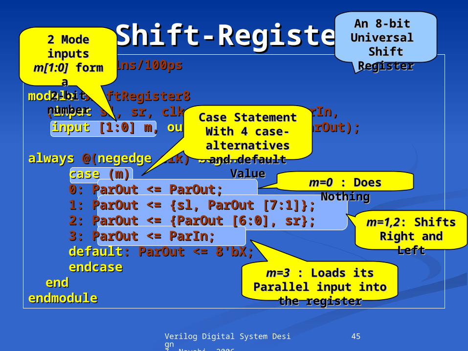
Shift-RegisterShift-Register`timescale`timescale 1ns/100ps 1ns/100ps
modulemodule ShiftRegister8 ShiftRegister8 ((inputinput sl, sr, clk, sl, sr, clk, inputinput [7:0] ParIn, [7:0] ParIn,
inputinput [1:0] m, [1:0] m, outputoutput regreg [7:0] ParOut); [7:0] ParOut); alwaysalways @( @(negedgenegedge clk) clk) beginbegin
casecase (m) (m) 0: ParOut <= ParOut;0: ParOut <= ParOut; 1: ParOut <= {sl, ParOut [7:1]};1: ParOut <= {sl, ParOut [7:1]}; 2: ParOut <= {ParOut [6:0], sr};2: ParOut <= {ParOut [6:0], sr}; 3: ParOut <= ParIn;3: ParOut <= ParIn; defaultdefault: ParOut <= 8'bX;: ParOut <= 8'bX;
endcaseendcase endend
endmoduleendmodule
An 8-bit An 8-bit Universal Universal
Shift Shift RegisterRegister
2 Mode 2 Mode inputs inputs
m[1:0]m[1:0] form form a a
2-bit 2-bit numbernumber
m=0m=0 : Does : Does NothingNothing
m=3m=3 : Loads its : Loads its Parallel input into Parallel input into
the registerthe register
m=1,2m=1,2: Shifts : Shifts Right and Right and
LeftLeft
Case StatementCase StatementWith 4 case-With 4 case-alternativesalternatives
and default Valueand default Value

46Verilog Digital System Design Z. Navabi, 2006
Shift-Register Shift-Register (Continued)(Continued)`timescale`timescale 1ns/100ps 1ns/100ps
modulemodule ShiftRegister8 ShiftRegister8 ((inputinput sl, sr, clk, sl, sr, clk, inputinput [7:0] ParIn, [7:0] ParIn,
inputinput [1:0] m, [1:0] m, outputoutput regreg [7:0] ParOut); [7:0] ParOut); alwaysalways @( @(negedgenegedge clk) clk) beginbegin
casecase (m) (m) 0: ParOut <= ParOut;0: ParOut <= ParOut; 1: ParOut <= {sl, ParOut [7:1]};1: ParOut <= {sl, ParOut [7:1]}; 2: ParOut <= {ParOut [6:0], sr};2: ParOut <= {ParOut [6:0], sr}; 3: ParOut <= ParIn;3: ParOut <= ParIn; defaultdefault: ParOut <= 8'bX;: ParOut <= 8'bX;
endcaseendcase endend
endmoduleendmodule
Shift Right:Shift Right:The The SLSL input is input is
concatenateconcatenated to the left d to the left of of ParOutParOut
Shifting the Shifting the ParOut ParOut to to the leftthe left

47Verilog Digital System Design Z. Navabi, 2006
DataData ComponentsComponents
MultiplexerMultiplexer Flip-FlopFlip-Flop
CounterCounter Full-AdderFull-Adder
Shift-RegisterShift-Register ALUALU
InterconnectionsInterconnections
ALUALU
ALU

48Verilog Digital System Design Z. Navabi, 2006
ALUALU`timescale`timescale 1ns/100ps 1ns/100ps
modulemodule ALU8 ( ALU8 (inputinput [7:0] left, right, [7:0] left, right, inputinput [1:0] mode, [1:0] mode, output regoutput reg [7:0] ALUout); [7:0] ALUout);
alwaysalways @(left, right, mode) @(left, right, mode) begin begin casecase (mode) (mode)
0: ALUout = left + right;0: ALUout = left + right; 1: ALUout = left - right;1: ALUout = left - right; 2: ALUout = left & right;2: ALUout = left & right; 3: ALUout = left | right;3: ALUout = left | right; defaultdefault: ALUout = 8'bX;: ALUout = 8'bX;
endcaseendcase endend
endmoduleendmodule
An 8-bit ALUAn 8-bit ALU
2-bit 2-bit modemode Input to Input to
select one of select one of its 4 its 4
functionsfunctions
AddAddSubtracSubtrac
ttANDANDOROR

49Verilog Digital System Design Z. Navabi, 2006
ALU (Continued)ALU (Continued)`timescale`timescale 1ns/100ps 1ns/100ps
modulemodule ALU8 ( ALU8 (inputinput [7:0] left, right, [7:0] left, right, inputinput [1:0] mode, [1:0] mode, output regoutput reg [7:0] ALUout); [7:0] ALUout);
alwaysalways @(left, right, mode) @(left, right, mode) begin begin casecase (mode) (mode)
0: ALUout = left + right;0: ALUout = left + right; 1: ALUout = left - right;1: ALUout = left - right; 2: ALUout = left & right;2: ALUout = left & right; 3: ALUout = left | right;3: ALUout = left | right; defaultdefault: ALUout = 8'bX;: ALUout = 8'bX;
endcaseendcase endend
endmoduleendmodule
An 8-bit ALUAn 8-bit ALU
The The Declaration of Declaration of ALUoutALUout both as both as outputoutput and and reg: reg:
Because of Because of assigning it assigning it
within a within a Procedural Procedural
BlockBlockBlocking Blocking AssignmeAssignme
ntsnts
defaultdefault alternativealternative
puts allputs all X Xss on on ALUOutALUOut
if if mode cmode containsontainsanything but anything but 11s s
andand 0 0ss

50Verilog Digital System Design Z. Navabi, 2006
DataData ComponentsComponents
MultiplexerMultiplexer Flip-FlopFlip-Flop
CounterCounter Full-AdderFull-Adder
Shift-RegisterShift-Register ALUALU
InterconnectionsInterconnections
InterconnectionsInterconnections
Interconnections

51Verilog Digital System Design Z. Navabi, 2006
InterconnectionsInterconnections
Partial Hardware Using Partial Hardware Using MUX8MUX8 and and ALUALU
BsideAsideInbus
select_source
ABinput
Function
Outbus
8 8
8 8
8
Mux8 and Mux8 and ALU examples ALU examples
forming a forming a Partial Partial
HardwareHardware

52Verilog Digital System Design Z. Navabi, 2006
InterconnectionsInterconnections
ALU8 U1 ( .left(Inbus), .right(ABinput), ALU8 U1 ( .left(Inbus), .right(ABinput), .mode(function), .ALUout(Outbus) );.mode(function), .ALUout(Outbus) );Mux8 U2 ( .sel(select_source), .data1(Aside), Mux8 U2 ( .sel(select_source), .data1(Aside),
.data0(Bside), .bus1 (ABinput)); .data0(Bside), .bus1 (ABinput));
Verilog Code of The Partial Hardware ExampleVerilog Code of The Partial Hardware Example
Instantiation Instantiation of of ALU8ALU8 and and
MUX8MUX8
u1u1 and and u2 u2 ::Instance Instance NamesNames
A Set of A Set of parenthesis parenthesis enclose port enclose port
connections to connections to the the
instantiated instantiated modulesmodules

53Verilog Digital System Design Z. Navabi, 2006
InterconnectionsInterconnections
ALU8 U1 ( Inbus, ABinput, function, Outbus );ALU8 U1 ( Inbus, ABinput, function, Outbus );Mux8 U2 ( select_source, Aside, Bside, ABinput );Mux8 U2 ( select_source, Aside, Bside, ABinput );
Ordered Port ConnectionOrdered Port Connection
An Alternative An Alternative format of port format of port
connectionconnection
The actual The actual portsportsof the of the
instantiatedinstantiatedcomponents components are excludedare excluded
The list of local The list of local signals in the signals in the same order as same order as
their connecting their connecting portsports

54Verilog Digital System Design Z. Navabi, 2006
ControllersControllers
ComponentComponentDescriptionDescription
DataDataComponentsComponents ControllersControllersControllers

55Verilog Digital System Design Z. Navabi, 2006
ControllersControllers
Controller OutlineController Outline
Decisions Based on : Inputs ,
Outputs , State
Issue Control Signal
Set Next State
Go to Next State

56Verilog Digital System Design Z. Navabi, 2006
ControllersControllers
Controller:Controller: Is wired into data part to control its flow of data.Is wired into data part to control its flow of data. The inputs to it controller determine its next states and The inputs to it controller determine its next states and
outputs.outputs. Monitors its inputs and makes decisions as to when and what Monitors its inputs and makes decisions as to when and what
output signals to assert.output signals to assert. Keeps the history of circuit data by switching to appropriate Keeps the history of circuit data by switching to appropriate
states.states. Two examples to illustrate the features of Verilog for describing Two examples to illustrate the features of Verilog for describing
state machines:state machines: SynchronizerSynchronizer Sequence DetectorSequence Detector

57Verilog Digital System Design Z. Navabi, 2006
ControllersControllers
ControllersControllers
SynchronizerSynchronizer SequenceSequenceDetectorDetector

58Verilog Digital System Design Z. Navabi, 2006
SynchronizerSynchronizer
ControllersControllers
SynthesizerSynthesizer SequenceSequenceDetectorDetector
Synchronizer

59Verilog Digital System Design Z. Navabi, 2006
SynchronizerSynchronizer
Synchronizing Synchronizing adataadata
Clk
adata
synched

60Verilog Digital System Design Z. Navabi, 2006
SynchronizerSynchronizer
`timescale`timescale 1ns/100ps 1ns/100ps
modulemodule Synchronizer ( Synchronizer (inputinput clk, adata, clk, adata, outputoutput reg synched); reg synched);
alwaysalways @( @(posedgeposedge clk) clk) if (adata == 0) synched <= 0; if (adata == 0) synched <= 0; elseelse synched <= 1; synched <= 1;
endmoduleendmodule
A Simple Synchronization CircuitA Simple Synchronization Circuit
If a If a 11 is is Detected on Detected on adataadata on the on the
rising edge of rising edge of clock, clock, synchedsynched becomes becomes 11 and and
remains remains 11 for at least one for at least one
clock period clock period

61Verilog Digital System Design Z. Navabi, 2006
Sequence DetectorSequence Detector
ControllersControllers
SynthesizerSynthesizer SequenceSequenceDetectorDetector
SequenceDetector

62Verilog Digital System Design Z. Navabi, 2006
Sequence DetectorSequence Detector
State Machine DescriptionState Machine Description
Searches Searches onon
it’s it’s aa inputinput
for the for the 110 110
SequenceSequence
When the When the sequence sequence
is detected, the is detected, the w Output w Output
becomes 1 and becomes 1 and stays 1 for a stays 1 for a
complete clock complete clock cyclecycle
If 110 is detected on a, then w gets 1, else w gets 0.
clk
a w

63Verilog Digital System Design Z. Navabi, 2006
Sequence DetectorSequence Detector
Sequence Detector State MachineSequence Detector State Machine
Initial
State
01
1
1
0
0
1
0reset
S00 0 10
S1 S2 S3
States are States are named:named:
s0s0 , , s1 s1 , , s2s2 , , s3s3
The State in The State in which the 110 which the 110 sequence is sequence is detected.detected.
It Takes at It Takes at least least
3 clock 3 clock periods to get periods to get to the to the s3s3 state state
A Moore A Moore MachineMachineSequence Sequence DetectorDetector

64Verilog Digital System Design Z. Navabi, 2006
Sequence DetectorSequence Detectormodulemodule Detector110 ( Detector110 (inputinput a, clk, reset, a, clk, reset, outputoutput w); w);
parameterparameter [1:0] s0=2'b00, s1=2'b01, s2=2'b10, s3=2'b11; [1:0] s0=2'b00, s1=2'b01, s2=2'b10, s3=2'b11;regreg [1:0] current; [1:0] current;
alwaysalways @( @(posedgeposedge clk) clk) beginbegin
ifif (reset) current = s0; (reset) current = s0; elseelse
casecase (current) (current) s0: s0: ifif (a) current <= s1; (a) current <= s1; elseelse current <= s0; current <= s0; s1: s1: ifif (a) current <= s2; (a) current <= s2; elseelse current <= s0; current <= s0; s2: s2: ifif (a) current <= s2; (a) current <= s2; elseelse current <= s3; current <= s3; s3: s3: ifif (a) current <= s1; (a) current <= s1; elseelse current <= s0; current <= s0; endcaseendcase
endend
assignassign w = (current == s3) ? 1 : 0; w = (current == s3) ? 1 : 0;
endmoduleendmodule
Verilog Code for Verilog Code for 110110 Detector Detector

65Verilog Digital System Design Z. Navabi, 2006
Sequence DetectorSequence Detector
modulemodule Detector110 ( Detector110 (inputinput a, clk, reset, a, clk, reset, outputoutput w); w);
parameterparameter [1:0] s0=2'b00, s1=2'b01, s2=2'b10, [1:0] s0=2'b00, s1=2'b01, s2=2'b10, s3=2'b11;s3=2'b11;
regreg [1:0] current; [1:0] current;
alwaysalways @( @(posedgeposedge clk) clk) beginbegin ifif (reset) current = s0; (reset) current = s0; elseelse
...................................................... ......................................................
Verilog Code for Verilog Code for 110110 Detector Detector
Behavioral Behavioral Description of Description of
the State the State MachineMachine
Parameter Parameter declarationdeclaration
defines constantsdefines constantss0s0, , s1s1, , s2s2, , s3s3
A 2-bit A 2-bit RegisterRegister

66Verilog Digital System Design Z. Navabi, 2006
Sequence DetectorSequence Detector
......................................................
......................................................alwaysalways @( @(posedgeposedge clk) clk) beginbegin
ifif (reset) current = s0; (reset) current = s0; elseelse
casecase (current) (current) s0: s0: ifif (a) current <= s1; (a) current <= s1; elseelse current <= s0; current <= s0; s1: s1: ifif (a) current <= s2; (a) current <= s2; elseelse current <= s0; current <= s0; s2: s2: ifif (a) current <= s2; (a) current <= s2; elseelse current <= s3; current <= s3; s3: s3: ifif (a) current <= s1; (a) current <= s1; elseelse current <= s0; current <= s0; endcaseendcase
endend
Verilog Code for Verilog Code for 110110 Detector Detector
if-elseif-else statementstatementchecks for checks for
resetresetAt the At the Absence Absence of aof a 1 1 on on
resetreset
The 4 Case-The 4 Case-alternativesalternatives
each correspond each correspond to a state of state to a state of state
machinemachine

67Verilog Digital System Design Z. Navabi, 2006
Sequence DetectorSequence Detector
State Transitions on Corresponding Verilog CodeState Transitions on Corresponding Verilog Code
s10
s20
s00
a=0
a=1
s1:
if (a)
current <= s2;
else
current <= s0;

68Verilog Digital System Design Z. Navabi, 2006
Sequence DetectorSequence Detector
endend................................................................................................................assignassign w = (current == s3) ? 1 : 0; w = (current == s3) ? 1 : 0;
endmoduleendmodule
Verilog Code for Verilog Code for 110110 Detector Detector
Assigns a Assigns a 11 to to w ow output when utput when
Machine Machine Reaches to Reaches to s3s3
StateState
Outside of Outside of the the alwaysalways
Block:Block:A A
combinationcombinational circuital circuit