1 transportand metro networks - uniroma2.it · transportand metro networks ... snmp simple ne or...
TRANSCRIPT

Transport and Metro NetworksTo automatically and easily route high-speed traffic in metro and transport networks optical
technologies are necessary. Use of optical circuits allows routing of traffic flows along desired
paths, with a limited degree of circuits reconfiguration which is suited to the need of
management with low dynamics (i.e. routes change very infrequently).
Routing techniques in optical networks are well-suited with the most effective Internet
technologies and with the great capacity needed to carry information over long distances. This
allowed (in Italy in 1990) network simplification, once much more complex, into only 2 layers:
• optical layer based on the use of different wavelengths, in practice the
level of transmission on which actual data flows.
1
53
• IP layer, consisting of data packets which can efficiently transport any
type of information (full integration of services).
level of transmission on which actual data flows.

Evolution of Transport Network
Modern transport networks assume a very simple structure, with an upper layer, which
integrates all the services in the form of IP packets, and a lower layer that provides the
necessary transport resources (circuits); this second layer is also capable of providing circuit
services directly to the large clients who request them (typically they are large companies
and other operators that do not have their own infrastructure).
New transport
2
New transport
network of Telecom
Italia (2011)
54
Access Network
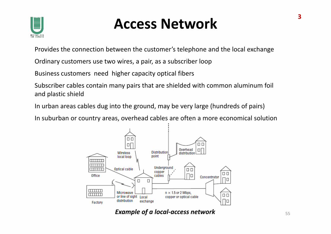
Provides the connection between the customer’s telephone and the local exchange
Ordinary customers use two wires, a pair, as a subscriber loop
Subscriber cables contain many pairs that are shielded with common aluminum foil
and plastic shield
In urban areas cables dug into the ground, may be very large (hundreds of pairs)
In suburban or country areas, overhead cables are often a more economical solution
Business customers need higher capacity optical fibers
3
In suburban or country areas, overhead cables are often a more economical solution
Example of a local-access network 55
Access Network Types
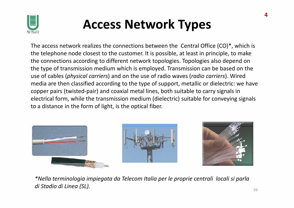
The access network realizes the connections between the Central Office (CO)*, which is
the telephone node closest to the customer. It is possible, at least in principle, to make
the connections according to different network topologies. Topologies also depend on
the type of transmission medium which is employed. Transmission can be based on the
use of cables (physical carriers) and on the use of radio waves (radio carriers). Wired
media are then classified according to the type of support, metallic or dielectric: we have
copper pairs (twisted-pair) and coaxial metal lines, both suitable to carry signals in
electrical form, while the transmission medium (dielectric) suitable for conveying signals
to a distance in the form of light, is the optical fiber.
4
to a distance in the form of light, is the optical fiber.
56
*Nella terminologia impiegata da Telecom Italia per le proprie centrali locali si parla
di Stadio di Linea (SL).

Distribution Frames
All subscriber lines are wired to the Main Distribution Frame (MDF)
At the telephone exchange (Central Office) end the wires are terminated on a
distribution frame, which provides a point where cross-connections can be made and
replaced anytime it is needed. The distribution frame has two sets of termination
points, one set for the permanent external cable termination, and another for the
permanent connection to interface circuits.
5
57
Role of the Main Distribution Frame
(incumbent local
exchange carrier)

Access Network in Italy 16
Primary network: connects a patch panel (permutatore) called Main Distribution Frame
(MDF) located in the central office (CO) to a Subloop Distribution Frame (SDF) located in a
street cabinet (armadio ripartilinea)
Secondary network: connects the SDF to the distribution box located at a building
(chiostrina o distributore)
Termination line (raccordo di terminazione): from the distribution box up to the
customers dwellings (unità abitative).
58
Stadio di Linea
armadio ripartilinea(MDF)
Central Office
SDF
RIF: P. Impiglia et al., “La rete in rame di Telecom Italia: caratteristiche e potenzialità per lo sviluppo delle
tecnologie xDSL”, Notiziario Tecnico Telecom Italia, Anno 13 n. 1 – giugno 2004, pp. 74-89.
Access Network in Italy 27
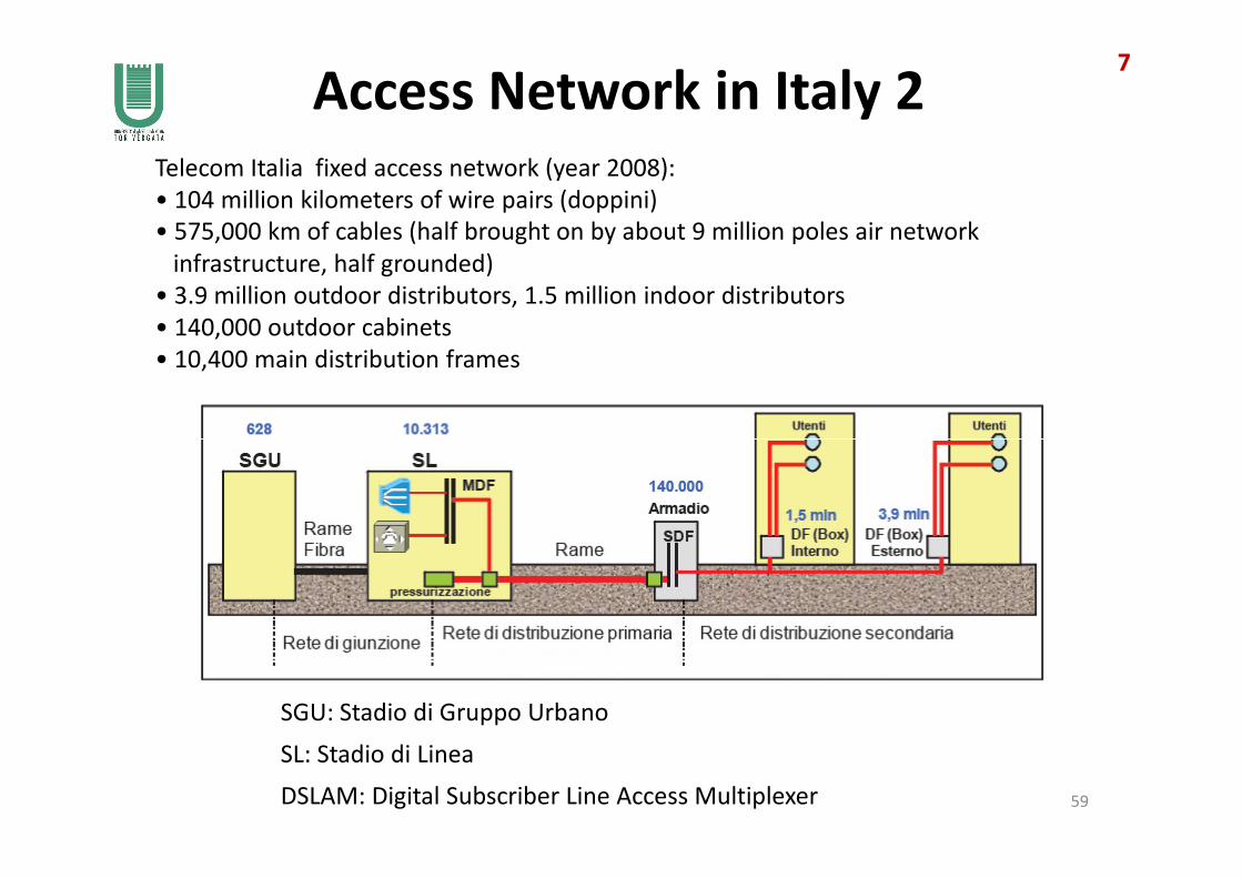
Telecom Italia fixed access network (year 2008):
• 104 million kilometers of wire pairs (doppini)
• 575,000 km of cables (half brought on by about 9 million poles air network
infrastructure, half grounded)
• 3.9 million outdoor distributors, 1.5 million indoor distributors
• 140,000 outdoor cabinets
• 10,400 main distribution frames
59
SGU: Stadio di Gruppo Urbano
SL: Stadio di Linea
DSLAM: Digital Subscriber Line Access Multiplexer

Main Distribution Frame8
60

Street Cabinets and Distributors
distributore
9
armadietto distributore
61

Cables in the access network of TI
• Primary network (from MDF to SDF): laid cables containing 1200 or 2400 pairs;
• Street cabinet: in input cables with 400 pairs;
• Capacity of a street cabinet: up to 1200 pairs; input 600 pairs (from primary
network); output 600 pairs (to secondary network);
• Telecom Italy generally in the street cabinet terminates 400 pairs incoming
from the primary network and 600 pairs outgoing to the secondary;
• The primary network cables can be: 400, 800, 1200, 1600 and 2400 pairs.
10
Examples: cables with 2400 pairs 62

Cable area (area cavo)
2400 pairs per cable
400 pairs into the street cabinet
200 pairs out, going towards the distributors
11
63

Cumulative distribution of local loop12
La distribuzione
cumulativa della
lunghezza del
collegamento di
utente in rame è
diversa nei vari
paesi. La rete
64
paesi. La rete
italiana è
mediamente più
corta di quella
degli altri paesi.

Network ManagementEfficient network management is key in helping a network operator improve services and
make them more competitive. A system that take care of control and supervisory
functions in a TLC network is called Operations Support System (OSS).
The Network OSS is in charge of the O&M (Operations & Maintenance) function, needed
to configure and provision network nodes, to monitor network health and performance.
Some of the factors which impact the configuration are: number of subscribers, peak-
hour call rate, nature of services, etc.
Operations functions include:
• subscriber management (e.g. manage subscriptions, collect charging data)
13
65
Maintenance functions include:
• continuous measure of parameters, such as Bit Error Rate (BER), loss of
synchronization, etc.
• network alarm monitoring (when a fault occurs, take corrective actions), network
statistics collection.
There are several Management Protocols, among them:
• SNMP developed by the TCP/IP (ARPANET) community
• CMIP developed by the ISO/OSI community
• TMN (Telecommunication Management Network) developed by the ITU.
• subscriber management (e.g. manage subscriptions, collect charging data)
• traffic monitoring and network control (needed to minimize the risk of network
overload by switching traffic away from overloaded connections)
• logging of various network nodes actions.
SNMP
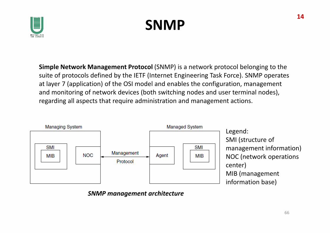
Simple Network Management Protocol (SNMP) is a network protocol belonging to the
suite of protocols defined by the IETF (Internet Engineering Task Force). SNMP operates
at layer 7 (application) of the OSI model and enables the configuration, management
and monitoring of network devices (both switching nodes and user terminal nodes),
regarding all aspects that require administration and management actions.
14
66
Legend:
SMI (structure of
management information)
NOC (network operations
center)
MIB (management
information base)
SNMP management architecture
TMN 1ITU-T defined a common management concept, TMN (Telecommunications Management
Network) to cover all aspects needed to centralize O&M in a multivendor environment.
TMN takes care of FCAPS functions, i.e., the following actions:
• Fault management: collect alarm information and take corrective action; detect system
malfunction and carry out measurements to locate faults
• Configuration management: change configuration of network elements; disconnect
subscriber who did not paid the bill
• Accounting: set accounting functions in network elements
• Performance: measure network performance to detect faults and bottlenecks in advance
15
67
TMN specifications:
• Physical architecture: what systems are needed in TMN and how they are interconnected
• Interface protocols: structure and types of messages to exchange information between
network elements and management systems
• Management functions: what functions in the network elements the network
management system should be able to access
• Information model: for each different system in the network, how each manageable
function is described in management messages.
• Performance: measure network performance to detect faults and bottlenecks in advance
• Security: detect security threats, i.e. collect data about users of a corporate network
frequently providing wrong security codes (in order to detect hackers).

TMN 2
TMN is separate from the actual telecommunications network, though network systems
must provide the management interfaces and functions that they are able to perform.
• Operations system (OS) for cen-
tralized network management
• Data communications network
(DCN) for management data
transfer
The physical architecture of TMN contains these elements:
16
68
transfer
• Mediation devices (MD) to adapt
proprietary management
interfaces to Q3 interfaces under
standardization
• Management functions integrat-
ed in the network elements (NEs)
of the telecommunications
network.

DCN
According to the TMN concept, the transmission of management data between
management workstations and network elements is separated from the transmission of
user data. The transportation network of management data is the DCN (Data
Communications Network ).
In TMN, a fault on a transmission link may disturb management messages that are
necessary for fault localization. Therefore, the DCN should be designed to be as
independent as possible from the network that transmits user data.
17
69Data Communications Network (DCN)