1. standards: conforming to usbv1.1 and 1.0, eia rs-485 ... · ut-890a usb/rs-485/rs-422 industrial...
TRANSCRIPT

UT-890AUSB/RS-485/RS-422 Industrial
Photoelectric Isolation Interface Converter User Manual
I. Summary
1 2 3
With rapid development of computer industry, USD is taking the place of various kinds of traditional low speed peripheral interfaces. However, RS-485/RS-422 interface designs are still used in many of the important facilities under current industrial environment, therefore, converter is used by many users to implement the data transmission from USB of a computer to RS-485/RS-422 equipments. UT-890A is a universal USB/RS-485/422 converter. without external power supply needed. Compatible with USB RS-422 and RS-485 standards UT-890A is capable to perform the conversion from single-ended USB signal into balance differenced signal of RS-422 or RS-485. Quick state- of-the -art tr ansien t voltage suppressor (TVS) and discharge tube are adopted to protect the RS-422/RS-485 interfaces. Under normal condit ions the TVS tube is in the state of high resistance. Howeverwhen both ends of the TVS tube are hit by a transient high energythe impedance at both ends can be depressed by the TVS at a very high speed, and after absorbing a high current, the voltage between the tw o e nds is suppressed and kept at a pre-set value, therefore no damage is caused to the electrical components behind by the transient high voltage impact. The protector can effectively restrain lightning or ESD (electro static discharge) with a protection voltage of 600W on each line for lightning surge and surge voltage or transient over voltage possibly caused up by various reasons, and at the same time, a high-speed transmission of RS-422/ RS-485 interfaces is ensured by the tiny capacitance between the poles. RJ-45 and DB9 male connectors are used for connection from RS-422 and RS-485 to other equipments. The unique I/O circuit of the internal zero delay auto transceiver contained in the converter controls the data stream direction automatically without any handshaking signal (for example RTS, DTR etc). The converter is plug-and-play without any jumper settings needed fo r mode shift between full duplex (RS-422) and half duplex (RS-485). All these features ensure a universal application on all the existing communication software and hardware interfaces. A reliable and stable point-to-point and point-to-multipoint communication can be ensured by UT-890A photoelectric isolation interface converter. For point-to-multipoint communication, as many as 32 interface facilities of RS-422 or RS-485 standard can be connected to each converter, and a high data transmission rate of 300-921.6Kbps can be achieved. Power indicator light and data traffic indicator light are also available with the converter for malfu nction indication. Conversions from USB to RS-422 and USB to RS-485
are supported.
RS-485/RS-422 output signals and PIN assignment
II. Performance parameters
1. Standards: conforming to USBV1.1 and 1.0, EIA RS-485
and RS-422, backwards compatible.
2. USB signals: VCC DATA+ DATA- GND FG
3. RS-485 signals: T+, T-, GND.
4. RS-422 signals: T+, T-, R+, R-, GND.
5. Working modes: asynchronous, point-to-point or point-
to-multipoint, 2-line half duplex and 4-line full duplex.
6. Direction control: adoption of automatic data stream
control for automatic recognition and control of data
transmission direction.
7. Baud rate: 300-921.6Kbps, automatic detection of the
transmission rate of the serial interface signal.
8. Workload ability: point-to-multipoint supported, a maximum
of 32 RS-422 or RS-485 interface equipments are supported.
9. Transmission distance: 1200 meters for RS-485/422 end
(when 9,600bps) and a maximum of 5 meters for USB.
10. Interface protection: 600W lightning strike and surge
protection and 5KV electrostatic protection.
11. Interface forms: A interface female connector, RJ-45 and
DB9 male connectors for USB end.
12. Signal indication: 3 indicator lights for Power (PWR),
Send (TXD) and Receive (RXD).
13. Transmission media: twisted-pair cable or shielded cable.
14. Transmission rate: 128,000bps to 300M.
38,400bps to 600M.
9,600bps to 1200M.
15. Dimensions: 1555mm 36mm 16mm.
16.Working environment: -25 to 70 , relative humidity
5% to 95%.
17. Transmission distance: 0-1200meters
18. Windows95/98/2000/XP/Vista/Win7/Linux and IMAG
are supported.
III. Connector and signal
UT-890A
USBPC1=>
RS-422 device
IV. Hardware ins ta l lment and appl icat ion
Read the user manual carefully before installing the UT-890A
interface converter. Put the signal cable of the equipment into the
USB socket. The product adopts the universal connector of USB,
DB-9 or RJ-45 for input and output interface with automatic mode
shift RS-485 or RS-422 mode without jumper setting. Either twisted
pair cable or shielded cable is applicable for easy installation or
un-installation. T/R+T/R- represents sending and receiving the
A+/B- RXD+/RXD- represents receiving the A+/B- GND
represents public underground line. Point-to-point and point-to-
multipoint and half duplex communication use the two lines of
T/R+ and T/R-, point-to-point and point-to-multipoint and full
duplex communication use the four lines of T/R+, T/R-, RXD+
and RXD-.
UT-890A interface converter supports the following 4
communication modes:
1. Point-to-point 4-line full duplex
2. Point-to-multipoint 4-line full duplex
3. Point-to-point 2-line half duplex
4. Point-to-multipoint 2-line half duplex
In order to prevent the signal reflection or interference
when converter is used in full-duplex or half-duplex mode,
a proper matching resistance should be connected at the
terminal of the line (120 1/4W).
V. Communication Connection Chart
USB to RS-422 conversion
1. RS-422 point-to-point / 4-line full duplex
N/A
N/A
DB9 connector(PIN)
1
2
3
4
5
6
7
8
9
T/R+
T/R-
RXD+
RXD-
GND
Output signal
Sending(A+)
Sending(B-)
Receiving(A+)
Receiving(B-)
RS-422 full duplex cabling RS-485 half duplex cabling
RS-485 (A+)
RS-485 (B-)
Null
Null
Grounding Grounding
N/A
N/A
UT-890A
UT-890A UT-890A
UT-890AUT-890A
UT-890A UT-890A
USBPC1=>
USBPC1=>
USB<=PC2
USBPC1=>
PC1=>USB
USBPC1=>
USB<=PC2
RS-422 device
RS-422 device
RS-422 device
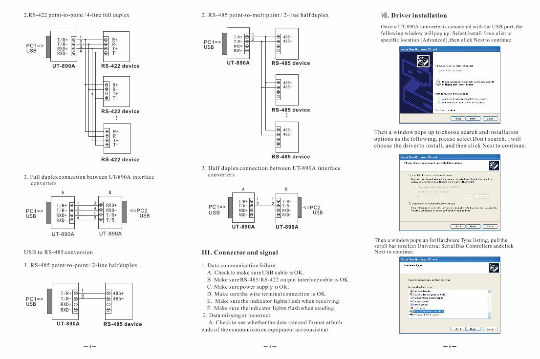
2.RS-422 point-to-point / 4-line full duplex 2. RS-485 point-to-multipoint / 2-line half duplex
RS-485 device
RS-485 device
RS-485 device
3. Full duplex connection between UT-890A interface converters
USB to RS-485 conversion
1. RS-485 point-to-point / 2-line half duplex
RS-485 device
3. Half duplex connection between UT-890A interface converters
III. Connector and signal
1. Data communication failure
A. Check to make sure USB cable is OK.
B. Make sure RS-485/RS-422 output interface cable is OK.
C. Make sure power supply is OK.
D. Make sure the wire terminal connection is OK.
E. Make sure the indicator lights flash when receiving.
F. Make sure the indicator lights flash when sending.
2. Data missing or incorrect
A. Check to see whether the data rate and format at both
ends of the communication equipment are consistent.
4 5 6
Once a UT-890A converter is connected with the USB port, the
following window will pop up. Select Install from a list or
specific location (Advanced), then click Next to continue.
Then a window pops up to choose search and installation options as the following, please select Don't search. I will choose the driver to install, and then click Next to continue.
Then a window pops up for Hardware Type listing, pull the scroll bar to select Universal Serial Bus Controllers and click Next to continue.
. Driver installation

9
In the following Select the device driver you want to
install for this hardware, click Have Disk to continue.
In the Locate File window, select CD path, then choose the directory Driver and click the button Open or double click to open. Select the driver mode as the following, thenclick the directory UT-890A to open.
In the Install From Disk window, click Browse to select
the path of the device driver.
7 8
In the following Install From Disk window, just click OK.
861
Select the applicable operation system, e.g. select and double
click to open WINXP.2003.2000 for Windows XP.
Select the file FTDIBUS.INF, then click Open.
USB installation information.
The following shows that the USB Serial Converter installation
is finished, then the system wizard will detect USB Serial Port
automatically.
Installation information has been located by the system as the following, just click Next to continue.
The following is the Found New Hardware Wizard for USB Serial Port click Next as for USB Serial Converter the same steps are omitted here.
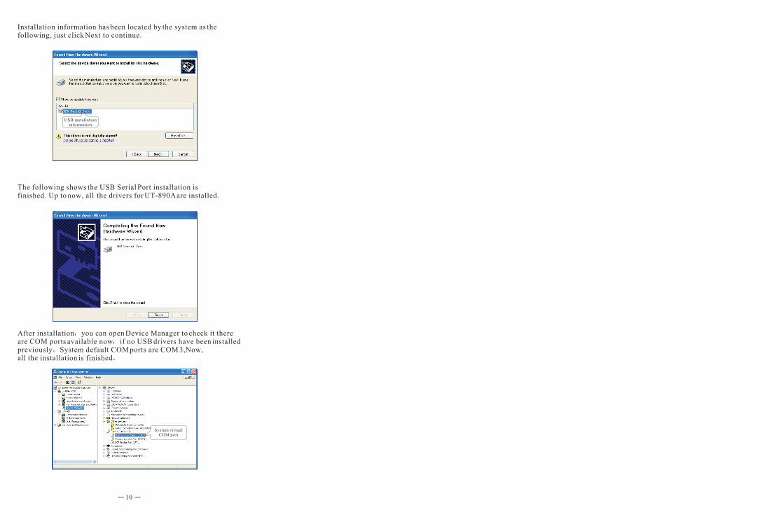
System virtual COM port
After installation you can open Device Manager to check it there are COM ports available now if no USB drivers have been installed previously System default COM ports are COM 3,Now, all the installation is finished
USB installation information.
Installation information has been located by the system as the following, just click Next to continue.
The following shows the USB Serial Port installation is finished. Up to now, all the drivers for UT-890A are installed.
10