1. specification - 212.113.105.12212.113.105.12/library/books/car/ssangyong/c205/c... · gcu...
TRANSCRIPT

10-31413-00
1. SPECIFICATIONDescription Specification
Glow plug Rated voltage 12 V
Operating voltage 6 to 16 V
Maximum temperature 1300°C
Operating temperature 1100°C
Glow plug control unit EMS operating voltage 6 to 16 V
Operating temperature -40°C to 110°C
Dark current Max. 1 mA

10-4
GCU (Glow plug Control Unit)
2. TIGHTENING TORQUE
No. Name Tightening torque
1 Glow plug 15 ± 1.5 Nm
2 Glow plug control unit bolt 10 ± 1.0 Nm
Glow plug

10-51413-00
1. OVERVIEWThe pre-heating system for D20DTF engine has the glow plug to the cylinder head (combustion chamber), and improves the cold start performance and reduces the emission level.The pre-heating resistor (air heater) is used to heat the intake air.This enables the diesel fuel to be ignited in low temperature condition.The ECU receives the information such as, engine rpm, coolant temperature, engine torque, etc., through CAN communication during pre-heating process; and the pre-heating control unit controls the pre-heating, heating during cranking and post-heating by the PWM control.
Glow plug Glow plug control unit (GCU)
Glow indicator Engine ECU (D20DTF)
10-6
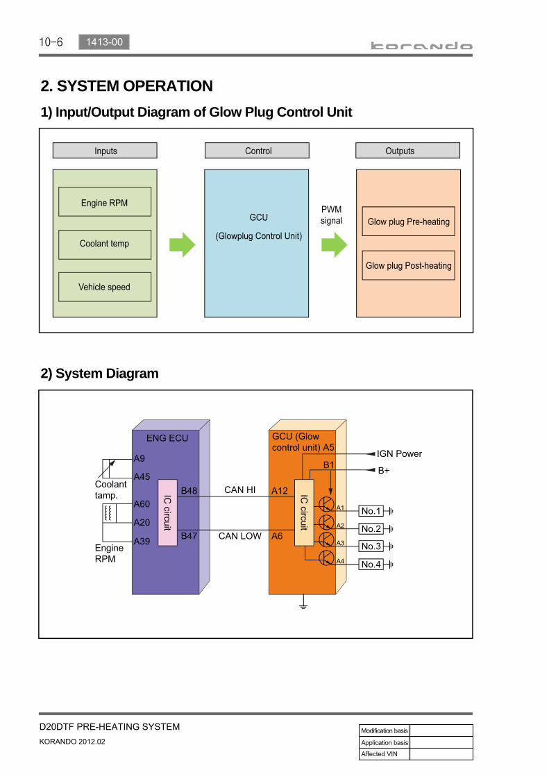
2. SYSTEM OPERATION1) Input/Output Diagram of Glow Plug Control Unit
2) System Diagram


10-8
3) Circuit Diagram

10-91413-00

10-10
4) System OperationGlow plug is installed in the cylinder head. It enhances the cold starting performance and reduces the exhaust gas during cold starting.ECU receives the various signals such as engine rpm, coolant temperature and vehicle speed through CAN communication lines. GCU controls the pre-heating, cranking and post-heating operations and monitors the glow plug. If GCU detects a problem, it sends the result to ECU.
(2) Operation of AQGS
Duty control area: Between 5 and 100%Frequency: 20 HzDuty ratio = (RMS voltage)²
(Battery voltage)²
1.
2.3.
(1) Characteristics of temperature and current in AQGSAQGS unit increases the glow plug temperature very rapidly (1,000˚C in 2 seconds).
FET (similar to transistor) for each cylinder in AQGS unit pre-heats the glow plug.If the glow plug temperature reaches to target temperature, the temperature is controlled by duty ratio.
1.2.3.
AQGS PWM Control Actual voltage pattern
AQGS unit supplies the power to glow plug. This shows the voltage and time supplied by AQGS by steps. As shown on the graph, the supplied voltage is decreased as the steps are continued. The 3rd step is to keep the temperature, not to raise it.
Frequency: 20~33HzPWM Control duty ratio- 1st step: 100%- 2nd step: 35%- 3rd step: 23%
10-111413-00
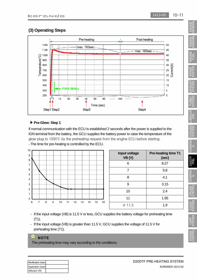
(3) Operating Steps
Pre-Glow: Step 1▶
If normal communication with the ECU is established 2 seconds after the power is supplied to the IGN terminal from the battery, the GCU supplies the battery power to raise the temperature of the glow plug to 1000℃ by the preheating request from the engine ECU before starting.
- The time for pre-heating is controlled by the ECU.
If the input voltage (VB) is 11.5 V or less, GCU supplies the battery voltage for preheating time (T1).If the input voltage (VB) is greater than 11.5 V, GCU supplies the voltage of 11.5 V for preheating time (T1).
-
-
The preheating time may vary according to the conditions.
Input voltage VB (V)
Pre-heating time T1 (sec)
6 8.27
7 5.8
8 4.1
9 3.15
10 2.4
11 1.95
≥ 11.5 1.9

10-12
During cranking: Step 2 and step 3▶
Step 2: If the ECU receives the cranking signal after pre-heating (step 1), the GCU supplies the voltage of 6.8 V for 1 sec to raise the temperature to 1,100℃.
Step 3: The GCU supplies the voltage of 5.1 V to keep the temperature at 1,000°C.
1.
2.Under fixed temperature: The AQGS unit supplies power for 30 seconds (Step 1 + Step 3) if no cranking signal is received after the step 1.During cranking: The step 3 is started after the step 2.
*
*
Post-glow: Step 4:▶
The post-heating is for reducing HC/CO after the engine is started. If the time for post-heating exceeds 180 sec., the GCU unit cuts off the power to each glow plug even if there is preheating request from the engine ECU.
Emergency glow▶
If no CAN signal is received for 4 seconds from the engine ECU after the IGN ON signal is input, the GCU performs emergency preheating (Step 3) for 30 seconds.

10-131413-00
Normal operating mode▶
This shows the components of preheating system in the pre-heating and the post-heating steps.

10-14
When there is no engine cranking signal after turning the ignition key ON▶