1 shared vs. switched ethernet (modeling and simulation using opnet) dr. khaled salah
Post on 20-Dec-2015
242 views
TRANSCRIPT
1
Shared vs. Switched Shared vs. Switched EthernetEthernet
(Modeling and Simulation using OPNET)(Modeling and Simulation using OPNET)
Dr. Khaled SalahDr. Khaled Salah
K. Salah 2
ObjectivesObjectives
Show Show basic featuresbasic features and capabilities of OPNET and capabilities of OPNET by exampleby example
Ethernet backgroundEthernet background How to:How to:
Build a small Ethernet LAN types Generate traffic: Poisson & Bursty Examine performance
Choose statistics Data collection Animation
K. Salah 3
Issues to InvestigateIssues to Investigate
How many users/node can be supported?How many users/node can be supported? Identify congestion and bottlenecksIdentify congestion and bottlenecks Node placement and load balancingNode placement and load balancing Assess the health of existing networkAssess the health of existing network
Resource utilization Delays
Capacity planningCapacity planning Test different vendor Ethernet productsTest different vendor Ethernet products ““what-if” scenarioswhat-if” scenarios
K. Salah 4
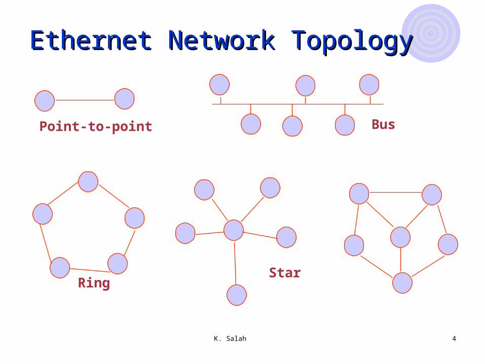
Ethernet Network TopologyEthernet Network Topology
Point-to-point Bus
RingStar
K. Salah 5
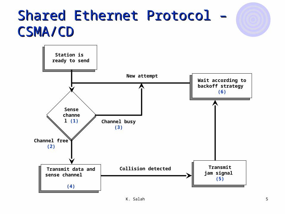
Shared Ethernet Protocol – CSMA/CDShared Ethernet Protocol – CSMA/CD
Station is ready to send
Station is ready to send
Station is ready to send
Transmit data and sense channel
(4)
Station is ready to send
Transmitjam signal
(5)
Station is ready to send
Wait according to backoff strategy
(6)
Sense channel
(1)
Channel free (2)
Channel busy (3)
Collision detected
New attempt
K. Salah 6
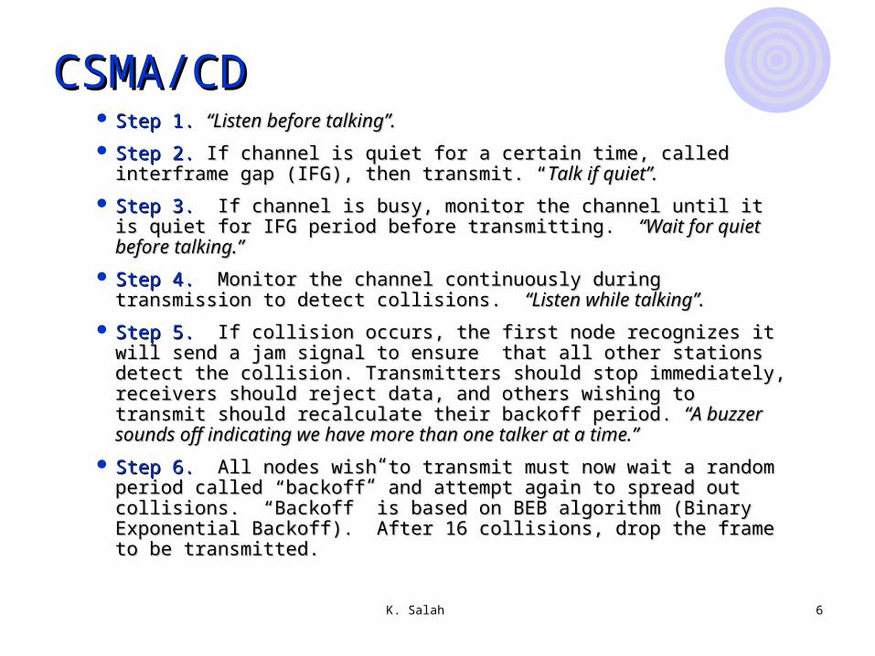
CSMA/CDCSMA/CD Step 1.Step 1. “Listen before talking”.“Listen before talking”.
Step 2.Step 2. If channel is quiet for a certain time, called interframe gap If channel is quiet for a certain time, called interframe gap (IFG), then transmit. “(IFG), then transmit. “Talk if quiet”.Talk if quiet”.
Step 3.Step 3. If channel is busy, monitor the channel until it is quiet for IFG If channel is busy, monitor the channel until it is quiet for IFG period before transmitting. period before transmitting. “Wait for quiet before talking.”“Wait for quiet before talking.”
Step 4.Step 4. Monitor the channel continuously during transmission to Monitor the channel continuously during transmission to detect collisions. detect collisions. “Listen while talking”.“Listen while talking”.
Step 5.Step 5. If collision occurs, the first node recognizes it will send a jam If collision occurs, the first node recognizes it will send a jam signal to ensure that all other stations detect the collision. signal to ensure that all other stations detect the collision. Transmitters should stop immediately, receivers should reject data, Transmitters should stop immediately, receivers should reject data, and others wishing to transmit should recalculate their backoff period. and others wishing to transmit should recalculate their backoff period. “A buzzer sounds off indicating we have more than one talker at a “A buzzer sounds off indicating we have more than one talker at a time.”time.”
Step 6.Step 6. All nodes wish to transmit must now wait a random period All nodes wish to transmit must now wait a random period called “backoff” and attempt again to spread out collisions. “Backoff” called “backoff” and attempt again to spread out collisions. “Backoff” is based on BEB algorithm (Binary Exponential Backoff). After 16 is based on BEB algorithm (Binary Exponential Backoff). After 16 collisions, drop the frame to be transmitted.collisions, drop the frame to be transmitted.

K. Salah 7
Coaxial CableCoaxial Cable Shared medium with BNC or vampire taps
RepeaterRepeater Layer 1 device that provides physical and electrical connections. It receives signals from one cable segment, regenerates,
retimes, and amplifies them, and then transmits these “revitalized” signals to another cable segment.
Transmits in both directions Joins two segments of cable No logical isolation of segments Greater distance is achieved
HubHub Used to describe a repeater Can be “repeater hub”, “switching hub”, bridging hub”.
NICNIC Performs layer-2 functions: framing, error detection, and flow
control. Performs layer-1 functions by converting the bits into electrical
signals using appropriate coding scheme.
Shared Ethernet ComponentShared Ethernet Component
K. Salah 8
Switched EthernetSwitched Ethernet
Point-to-pointPoint-to-point No CollisionNo Collision
Larger Network diameter 10GbE that can go more than 50 km over SMF.
Higher Throughput Smaller Latencies No Congestion Collapse
K. Salah 9
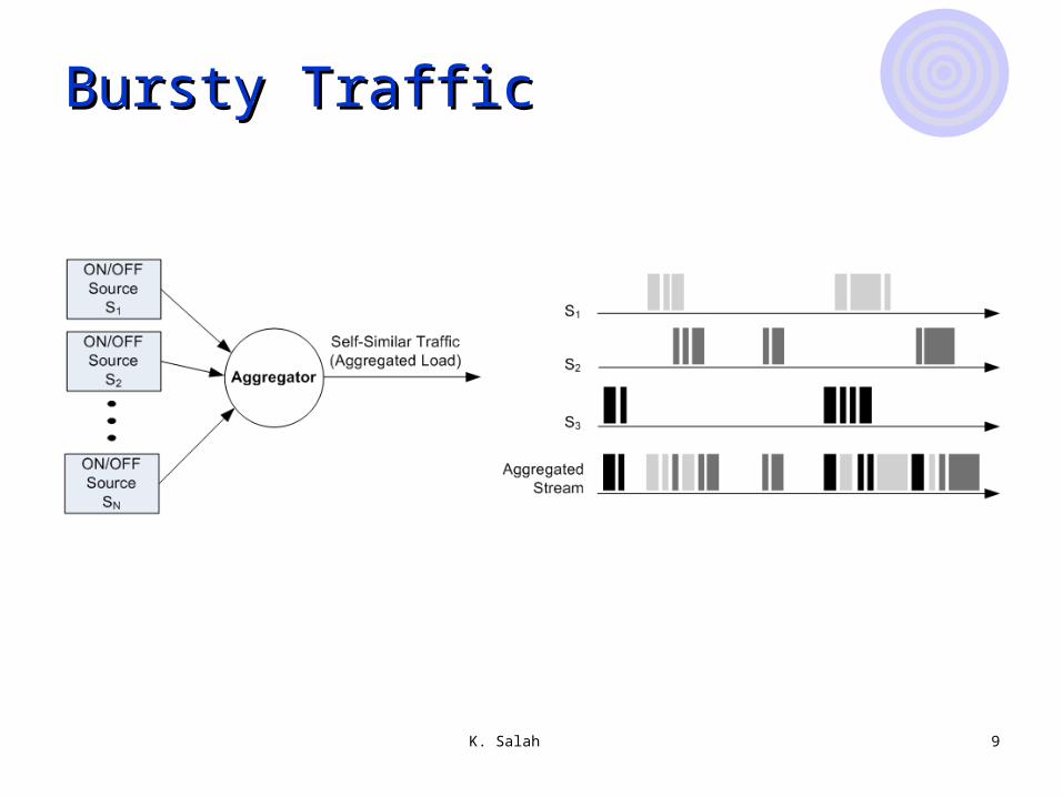
Bursty TrafficBursty Traffic
K. Salah 10
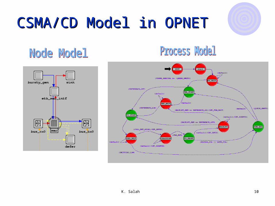
CSMA/CD Model in OPNETCSMA/CD Model in OPNET
K. Salah 11
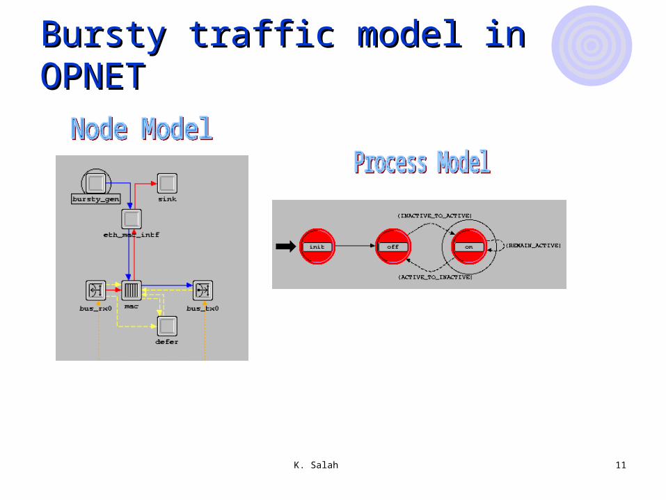
Bursty traffic model in OPNETBursty traffic model in OPNET
K. Salah 12
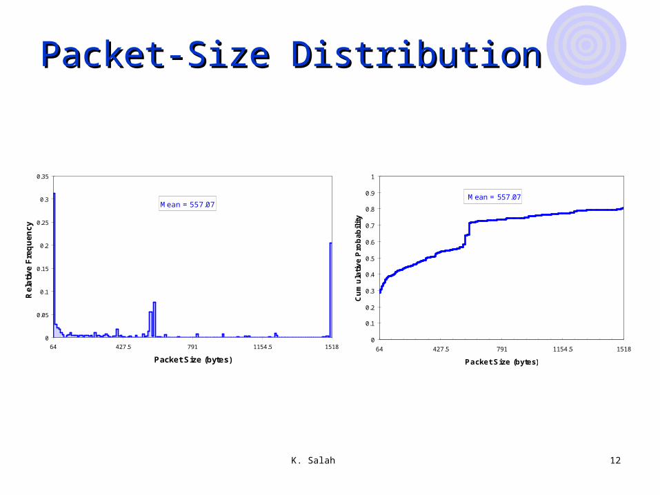
Packet-Size DistributionPacket-Size Distribution
Mean = 557.07
0
0.05
0.1
0.15
0.2
0.25
0.3
0.35
64 427.5 791 1154.5 1518
Packet Size (bytes)
Re
lati
ve
Fre
qu
en
cy
BestFit Trial VersionFor Evaluation Purposes OnlyBestFit Trial VersionFor Evaluation Purposes OnlyBestFit Trial VersionFor Evaluation Purposes OnlyBestFit Trial VersionFor Evaluation Purposes OnlyBestFit Trial VersionFor Evaluation Purposes OnlyBestFit Trial VersionFor Evaluation Purposes OnlyBestFit Trial VersionFor Evaluation Purposes OnlyBestFit Trial VersionFor Evaluation Purposes Only
Mean = 557.07
0
0.1
0.2
0.3
0.4
0.5
0.6
0.7
0.8
0.9
1
64 427.5 791 1154.5 1518
Packet Size (bytes)C
um
ula
tiv
e P
rob
ab
ilit
y
K. Salah 13
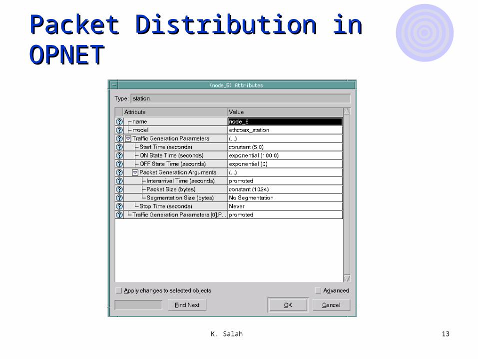
Packet Distribution in OPNETPacket Distribution in OPNET
K. Salah 14
Creating Network TopologiesCreating Network Topologies
Importing the topologyImporting the topologyPlacing each individual node from the Placing each individual node from the
Object Palette into the workspaceObject Palette into the workspaceCrating a new network topology by using Crating a new network topology by using
Rapid ConfigurationRapid Configuration

K. Salah 15
StatisticsStatistics
Two ways to collect statisticsTwo ways to collect statistics Object statistics
from individual nodes Global statistics
From the entire network as whole
K. Salah 16
Data CollectionData Collection
VectorVector Time-dependent series of values
ScalarScalar Parametric relationships
AnimationAnimation visualization

K. Salah 17
Vector vs. ScalarVector vs. Scalar
Scalar data graphScalar data graphVector data graphsVector data graphs
K. Salah 18
OPNET AnimationOPNET Animation
Used for debuggingUsed for debugging Extremely useful for new or modified protocols
Allows to visualize a simulation while Allows to visualize a simulation while running it.running it.
Gives insight how a certain protocol works Gives insight how a certain protocol works (RIP, BGP, OSPF, IPv4, IPv6, etc.)(RIP, BGP, OSPF, IPv4, IPv6, etc.)
The animation can also be run after the The animation can also be run after the simulation is over, from a history file. simulation is over, from a history file.
K. Salah 19
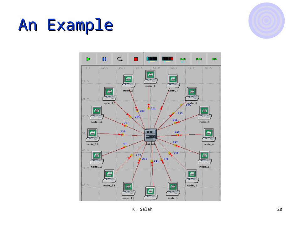
Setup AnimationSetup Animation
To view animation, click on Simulation and To view animation, click on Simulation and select Record Animation For Subnet. You select Record Animation For Subnet. You have to do this before you do a simulation have to do this before you do a simulation run.run.
Animation Viewer/PlayerAnimation Viewer/Player Slow Fast Step Pause
K. Salah 20
An ExampleAn Example
K. Salah 21
DebuggingDebugging
A good debugging tool is the Simulation A good debugging tool is the Simulation Log. You can check for warnings and Log. You can check for warnings and errorserrors
Click on ResultsClick on ResultsThen Click on Open Simulation LogThen Click on Open Simulation Log
K. Salah 22
Coming up examples Coming up examples
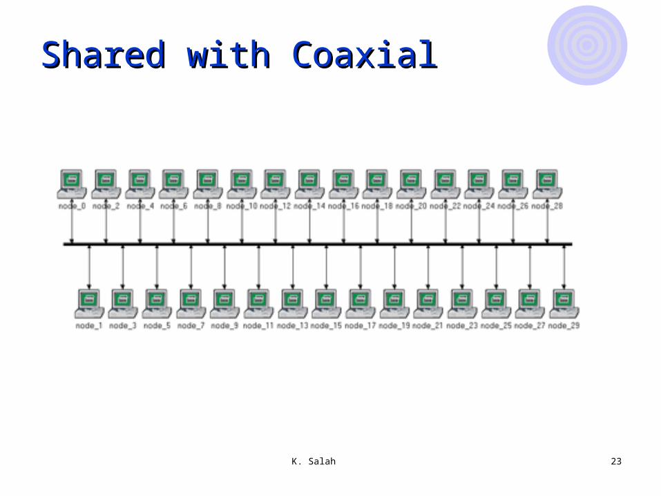
Shared Ethernet with bus topologyShared Ethernet with bus topology Coaxial cable
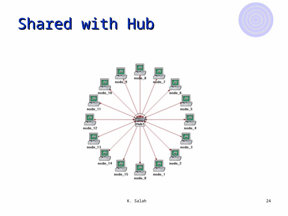
Shared Ethernet with star topologyShared Ethernet with star topology Hub
Switched Ethernet with star topologySwitched Ethernet with star topology Switch
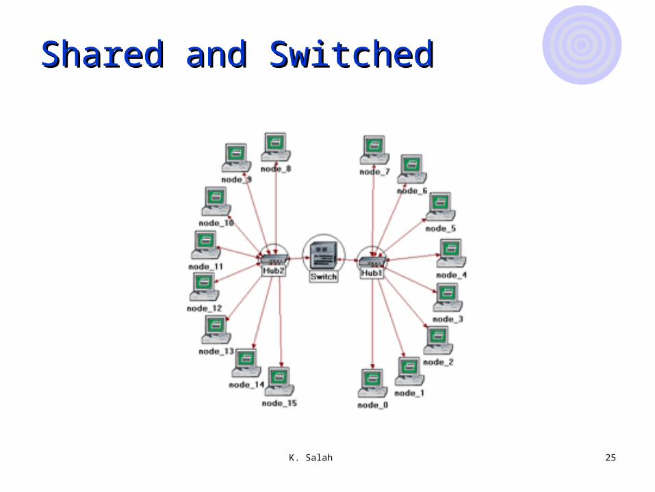
Mix Mix Hub and Switch
K. Salah 23
Shared with CoaxialShared with Coaxial
K. Salah 24
Shared with HubShared with Hub
K. Salah 25
Shared and SwitchedShared and Switched
26
demosdemos
(step-by-step instructions are available)(step-by-step instructions are available)