1 semi-solid forming of aluminium and steel introduction and overview€¦ · · 2009-04-17the...
TRANSCRIPT

1Semi-solid Forming of Aluminium and Steel –Introduction and Overview�Gerhard Hirt, Liudmila Khizhnyakova, Ren�e Baadjou, Frederik Knauf, and Reiner Kopp
1.1Introduction
The origins of semi-solidmetal forming date back to the early 1970s, when Flemingsand co-workers studied theflowbehaviour ofmetals in a semi-solid state [1]. Soon thefirst industrialization by Alumax and ITT-TEVES was achieved for automotive appli-cations such as chassis components, brake cylinders, rims and so on. Many patents,particularly concerning the production of the required specific primary material,hindered wider development during that time. At the end of the 1980s, an intensivedevelopment period started also in Europe. With the alternative electromagneticstirring methods implemented by Pechiney (France), Ormet (USA) and SAG(Austria), primary material in variable dimensions and quality became available.New heating technologies and online-controlled pressure casting machines consti-tuted the basis for appropriate production equipment. This led to various impressivemass production applications in the field of chassis (e.g. Porsche, DaimlerChrysler,Alfa Romeo) and car body components (e.g. Audi, Fiat, DaimlerChrysler, in additionto lower volume production for other fields. However, due to the increasing contestwith the rapidly improving quality of highly cost-effective fully liquid castingprocesses, some of these activities have been terminated in the meantime. Onereason, namely the cost disadvantage caused by the use of special primary material,could be reduced by the introduction of new rheocasting processes, which helped tokeep several applications of forming in the semi-solid state. For example, STAMPAL(Italy) changed the production of some components from �classical thixocasting� to�new rheocasting�. Other challenges are the narrow process windows for billetproduction, reheating and forming, which have to be maintained to achieve highlyrepeatable production. This requires a fundamental and detailed understanding ofthe physical basics of each process step, taking into account details of the materialbehaviour and microstructure development.
� A List of Abbreviations can be found at theend of this chapter.
Thixoforming: Semi-solid Metal Processing. Edited by G. Hirt and R. KoppCopyright � 2009 WILEY-VCH Verlag GmbH & Co. KGaA, WeinheimISBN: 978-3-527-32204-6
j1

The worldwide intensive efforts in industry and science to develop semi-solidmetal forming are motivated by the significant technological and scientific potentialwhich these innovative technologies can provide:
. Compared with conventional casting, the high viscosity of semi-solid metal allowsmacroscopic turbulence during die filling to be avoided and subsequently reducespart defects that could arise from air entrapment. A second advantage is that due tohigh solid fraction of about 40% during die filling the loss of volume duringcomplete solidification is reduced, leading to correspondingly reduced shrinkageporosity or allowing higher cross-sectional changes than are possible in conven-tional castings. Furthermore, the low gas content leads to microstructures whichare suitable forwelding andheat treatment even in veryfiligree components, whichamong others is an essential argument for the existing thixocasting serial produc-tion of aluminium alloys for the automotive industry. In addition, the loweredprocess temperature of the semi-solidmetal can lead to a significant increase in toollife compared with conventional die casting.
. Compared with conventional forging, thixoforming offers significantly reduced form-ing loads and the opportunity to produce complex geometry components, whichcould not be produced by forging. In addition the near net shape capabilities ofthixoforming reducemachining to aminimum.However, theusuallywroughthigh-strength aluminiumalloys,whichare typically used in forging, arenotwell suited forsemi-solid forming, especially because they have a tendency for hot cracking duringsolidification. Therefore, the superiormechanical properties of forged componentscannot completely be achieved by thixoforming. Also, the production cycles inforging are much shorter than in thixoforming, which requires time for solidifica-tion. Accordingly, a substitution of forging by semi-solid forming will only offereconomic benefits if parts with significant added value can be produced. This couldbe achieved by increased geometric complexity, by weight saving when substitutingsteel by aluminium or by production of composite components. Additional benefitsmay arise if some final machining or joining operations can be avoided.
Industrial thixocasting of aluminium alloys is based on the benefits in comparisonwith casting processes, which have led to various serial production methods in spiteof the additional costs for primary material and investment costs for heatingequipment. However, there is strong competition with highly economical andimproved casting processes such as vacuum casting, squeeze casting, fully automat-ed die casting and optimized casting aluminium alloys such as AlMg5SiMn. Thisstrictly limits the range of economically feasible semi-solid forming applications tosuch components, which fully exploit the technical advantages listed above. Inaddition, the narrow process window and the complexity of the process chain requiresignificant experience in semi-solid metal series production, which is today availablefor example at SAG (Austria), Stampal (Italy), AFT (USA), and Pechiney (France).Thixoforming of higher melting iron-based alloys has also been investigated in early
work at MIT [2, 3], Alumax [4] and Sheffield University [5]. However, these activities,which showed impressive success, nevertheless faced significant technological
2j 1 Semi-solid Forming of Aluminium and Steel – Introduction and Overview

challenges and they were not in the centre of general interest, which at that time wasmuch more focused on aluminium alloys. Not before the middle of the 1990s didsemi-solid forming of steel become the focus of various research activities world-wide [6–14]. In these projects, the general feasibility of semi-solid forming of highermelting point alloys was demonstrated. The major challenges, however, which stillneed to be overcome, aremainly related to the high temperature range, which causeshigh thermal loading of tools and dies and difficulties in achieving a homogeneoustemperature distribution in the billet. Also, the tendency for oxidation and scaleformation and in some alloys the complexmicrostructure evolution during reheatingcause difficult problems to solve.Concerning the competition between semi-solid forming of steels and conven-
tional casting and forging technologies, the situation differs significantly from thatdiscussed above for aluminium. The reason is that cost-efficient permanent mouldcasting processes for steel do not exist. This is currently restricted by the high thermalloading that the dies and injection systems would have to face. Thixoforming,however, is performed at lower temperatures and, evenmore important, the internalenergy of semi-solid metals is significantly reduced compared with the fully liquidstate. This means that using the high fluidity of semi-solid steels, it might for thefirst time become possible to manufacture near net shape steel components withcomplicated geometry in a single-step permanent mould process.Conventionally forged steel components may also be geometrically complicated,
but the relation betweenflow length andwall thickness ismuch smaller than in semi-solid forming. Also, complex geometries require multi-stage forging processes andsignificantly more final machining. This indicates that the application potential forsemi-solid forming of steels could be significantly higher than for aluminium alloys.However, there are still challenging technical and scientific problems to solve.The goals of this book are as follows:
. to summarize fundamental knowledge and technological applications for semi-solid forming;
. to contribute to a better understanding of the governing relations between theprocess parameters and the achieved part quality and to present selected techno-logical solutions to overcome existing process challenges.
Since several books and longer reviews have already been written focusing onsemi-solid forming of aluminium alloys and with respect to the market potentialdescribed above, most of this book is dedicated to semi-solid forming of steels.However, themethods applied andmost of the results achieved are also valid for otheralloy systems.The rest of this introductory chapter will give a brief overview of the development
and state of the art of the technology of semi-solidmetal forming. Part One covers thematerial science aspects such asmicrostructure evolution and characterization in thesemi-solid condition. Part Two is dedicated tonumericalmodelling of the constitutivematerial behaviour and its application in process modelling. This involves both two-phase modelling and micro–macro coupling, since both must be taken into accountfor an adequate representation of the material behaviour. Part Three is related to tool
1.1 Introduction j3

and die technologies, which are one of themajor challenges for semi-solid forming ofhigh-temperature alloys such as steel. Part Four presents technological applicationsand process alternatives of semi-solid forming.
1.2Early Work on Flow Behaviour and Technology Development
1.2.1Basic Findings Concerning the Rheology of Metals in the Semi-solid Condition
The development of semi-solid forming of metals dates back to early work ofFlemings in the 1970s [15]. He and his co-workers studied the behaviour of solidi-fying metallic melts under conditions in which they form a suspension of globularprimary solid particles in a liquid metallic melt (Figure 1.1b). At that time, this wasachieved by stirring the slurry while cooling it to the desired temperature. The initialfindings clearly showed that under such conditions the viscosity of metals in thesemi-solid state depends on the solid fraction, shear rate and time history. Eventhough this behaviour is to be expected for two-phase emulsions, it was a fairly newdiscovery for metallic systems, which under normal conditions would have shown adendritic microstructure (Figure 1.1a).The observations concerning the flow behaviour, which were achieved in Couette-
type rheometers, may be summarized as follows:
. Influence of solid fractionThe viscosity strongly depends on the volume fraction of solid particles, typicallyshowing a steep increase when the solid fraction becomes higher than 35–50%.
Figure 1.1 (a) Dendritic and (b) globular microstructure.
4j 1 Semi-solid Forming of Aluminium and Steel – Introduction and Overview

. Influence of shear rateVarying the shear rate in the rheometer revealed that the apparent viscosity alsodepends strongly on the actual shear rate. For example, in an Sn–15Pb alloy at asolid fraction of 40%, the viscosity varies from about 106 Pa s at a shear rate0.001 s�1,which is typical for glassworking, to 10�2 Pa s at 200 s�1, which is similarto bicycle oil [15].
. Influence of time historyIf semi-solid slurries are allowed to stand, the globular particles tend to agglomer-ate and the viscosity increases with time. If the material is sheared, the agglom-erates are broken up and the viscosity falls. This time-dependant thixotropicbehaviour is shown schematically in Figure 1.2.
Many studies have been performed since then to investigate this behaviour inmore detail for different alloys, to explain the governing mechanisms and to derivemodels to describe the material response. One mechanism, which distinguishessemi-solid metal slurries from other suspensions, is that the particle shape and sizevary irreversibly with time, as shown in Figure 1.3.
Figure 1.2 Time-dependent thixotropic behaviour.
Figure 1.3 Schematic illustration of evolution of structure duringsolidification with vigorous agitation: (a) initial dendriticfragment; (b) dendritic growth; (c) rosette; (d) ripened rosette;(e) spheroid [15].
1.2 Early Work on Flow Behaviour and Technology Development j5
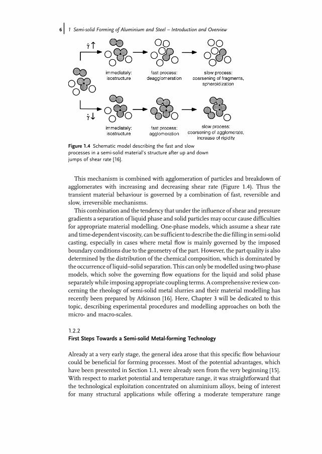
This mechanism is combined with agglomeration of particles and breakdown ofagglomerates with increasing and decreasing shear rate (Figure 1.4). Thus thetransient material behaviour is governed by a combination of fast, reversible andslow, irreversible mechanisms.This combination and the tendency that under the influence of shear and pressure
gradients a separation of liquid phase and solid particles may occur cause difficultiesfor appropriate material modelling. One-phase models, which assume a shear rateand time-dependent viscosity, can be sufficient to describe the diefilling in semi-solidcasting, especially in cases where metal flow is mainly governed by the imposedboundary conditions due to the geometry of the part. However, the part quality is alsodetermined by the distribution of the chemical composition, which is dominated bythe occurrence of liquid–solid separation. This can only bemodelled using two-phasemodels, which solve the governing flow equations for the liquid and solid phaseseparately while imposing appropriate coupling terms. A comprehensive review con-cerning the rheology of semi-solid metal slurries and their material modelling hasrecently been prepared by Atkinson [16]. Here, Chapter 3 will be dedicated to thistopic, describing experimental procedures and modelling approaches on both themicro- and macro-scales.
1.2.2First Steps Towards a Semi-solid Metal-forming Technology
Already at a very early stage, the general idea arose that this specific flow behaviourcould be beneficial for forming processes. Most of the potential advantages, whichhave been presented in Section 1.1, were already seen from the very beginning [15].With respect to market potential and temperature range, it was straightforward thatthe technological exploitation concentrated on aluminium alloys, being of interestfor many structural applications while offering a moderate temperature range
Figure 1.4 Schematic model describing the fast and slowprocesses in a semi-solid material�s structure after up and downjumps of shear rate [16].
6j 1 Semi-solid Forming of Aluminium and Steel – Introduction and Overview

below 600 �C for semi-solid processing. However, the idea of producing the slurry bycooling from liquid turned out not to be a practical solution at that time and the break-through was not achieved until an alternative route was found. This new route wasbased on the idea that a suitable suspension of globular solid particles in a liquidmeltcould also be achieved by reheating solidified billets to the desired liquid fraction,if these billets were prepared to have a fine-grained globular microstructure.Accordingly, the emerging technology, which was used to demonstrate the feasibilityto manufacture complex parts, consisted of three major steps [18]:
. Billet production: Proprietary technologies were developed to cast billets with a fine-grained globular microstructure. These technologies included direct chill castingwith active (mechanical or electromagnetic) or passive stirring and thermomecha-nical processing of solid feedstock (see Sections 1.3.1.1 and 1.3.1.2).
. Reheating to the semi-solid condition: The necessity to heat billets accurately andhomogeneously to the semi-solid condition required specific heating strategies andthe development of adequate equipment and control systems. Inductive heatingwas preferably used, but also conventional radiation/convection-type furnaceswere applied in series production (see Sections 1.3.2.1 and 1.3.2.2).
. Forming operations and applications: After reheating, the semi-solid billet is usuallyformed into the final shape in just one forming operation. Two basic formingprinciples are generally applicable:
– In thixocasting the billet is injected into a closed die, as in high-pressure diecasting.
– In thixoforging, the billet is formed by using an upper and a lower die whichmove against each other. Using these principles, relatively complex and chal-lenging demonstrator parts were already manufactured in the 1980s, such asautomotive brake master cylinders, automobile wheels, electrical connectors,valve bodies and plumbing fittings [18].
1.3Today�s Technologies of Semi-solid Metal Forming
Over the years, a family of process routes and process alternatives for semi-solidforming have evolved from this early work. Reviews concerning these technologiesand their industrial application have been published [18–21]. Some of them havesucceeded in being applied in industrial mass production; others are still limited tothe laboratory scale. Generally, these process routes can be structured according toFigure 1.5.Following the early idea of separating the slurry preparation from the forming
operation, various methods to provide solid billets with a fine-grained globularmicrostructure have been developed. These will be briefly discussed in general inSection 1.3.1, whereas specific details are given later in Chapter 4. Before forming,
1.3 Today�s Technologies of Semi-solid Metal Forming j7
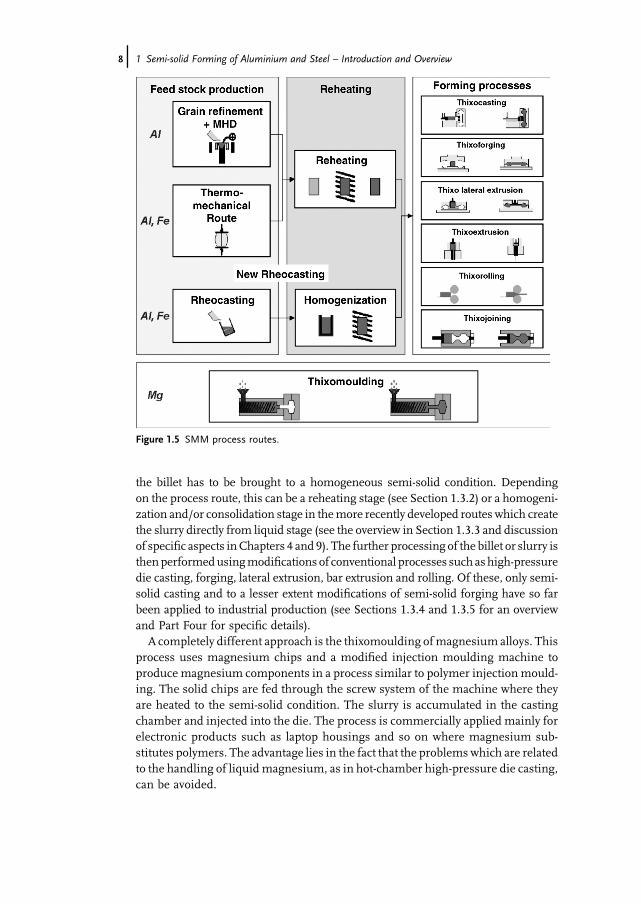
the billet has to be brought to a homogeneous semi-solid condition. Dependingon the process route, this can be a reheating stage (see Section 1.3.2) or a homogeni-zation and/or consolidation stage in themore recently developed routes which createthe slurry directly from liquid stage (see the overview in Section 1.3.3 and discussionof specific aspects inChapters 4 and 9). The further processing of the billet or slurry isthenperformedusingmodifications of conventional processes such as high-pressuredie casting, forging, lateral extrusion, bar extrusion and rolling. Of these, only semi-solid casting and to a lesser extent modifications of semi-solid forging have so farbeen applied to industrial production (see Sections 1.3.4 and 1.3.5 for an overviewand Part Four for specific details).A completely different approach is the thixomoulding ofmagnesium alloys. This
process uses magnesium chips and a modified injection moulding machine toproduce magnesium components in a process similar to polymer injection mould-ing. The solid chips are fed through the screw system of the machine where theyare heated to the semi-solid condition. The slurry is accumulated in the castingchamber and injected into the die. The process is commercially applied mainly forelectronic products such as laptop housings and so on where magnesium sub-stitutes polymers. The advantage lies in the fact that the problems which are relatedto the handling of liquid magnesium, as in hot-chamber high-pressure die casting,can be avoided.
Figure 1.5 SMM process routes.
8j 1 Semi-solid Forming of Aluminium and Steel – Introduction and Overview

1.3.1Preparation of Billets for Semi-solid Forming
1.3.1.1 Direct Chill CastingDirect chill casting is an established process for the production of aluminium billetsfor forging, extrusion and rolling. Accordingly, it was an obvious idea to use thisprocess to produce billets with a fine-grained globular microstructure that wererequired for the thixoforming route. Transferring the observations from the earlyrheometer tests initially resulted in laboratory concepts using active mechanicalstirring to produce a slurry before feeding it into the direct chill (DC) casting mould(Figure 1.6a). This, however, was soon replaced by DC casting with magnetohydro-dynamic (MHD) stirring in the mould, thus directly influencing the solidification byvigorous agitation to avoid the formation of dendritic structures. Patents [22–24]introduced variations of this idea, such as circumferential or vertical stirring(Figure 1.6 c, d) and a combination of both stirring types.Alternatives to electromagnetic or active mechanical stirring are the so-called
passive stirring and chemical grain refinement. In passive stirring (Figure 1.6b), theliquid metal is forced to flow through a system of obstacles (i.e. ceramic balls) whilebeing cooled into the semi-solid range. The shear generated by this forced flowprohibits the formation of large dendrites and creates �nuclei� of crystals by dendritefragments. This process was developed byMoschini [25] and has been used to supplyfeedstock for the mass production of pressure-tight fuel rails by semi-solid casting.Also in conventional DC casting of forging or extrusion feedstock, the goal is to
produce a fine-grained and homogeneous microstructure. For this purpose, variousmethods of chemical grain refinement have been developed, providing a largenumber of �nuclei� by addition of Al–5Ti–B particles. It has been shown that theseprocedures in some cases can be adopted to produce feedstock which exhibits thetypical microstructure and flow behaviour for semi-solid forming [26, 27].
Figure 1.6 Stirring modes: (a) mechanical stirring; (b) passivestirring; (c) electromagnetic �vertical� stirring; (d) electromagnetic�horizontal� stirring.
1.3 Today�s Technologies of Semi-solid Metal Forming j9

1.3.1.2 Thermomechanical TreatmentIn addition to casting, there also exist solid working routes to produce feedstock forsemi-solid forming. These routes typically consist of plastic deformation followed byrecrystallization during the reheating stage. If reheating is then performed into thesemi-solid range, the fine grains start to melt at their boundaries, resulting inglobular particles surrounded by liquid. Depending on whether the plastic deforma-tion has been performed as hot working or cold working, the process is referred to asthe strain induced melt activated (SIMA) route [22, 28].Economically, these thermomechanical routes cannot compete withMHD casting
of the typically applied aluminium alloys since they involve an additional extrusionstepwhich is usually limited to smaller diameters.However, somehigh-performancealloys and composites are generally delivered in extruded condition (i.e. after sprayforming) and can be used in this condition for semi-solid forming.However, regarding thixoforming of steels, the thermomechanical route has so far
been the most suitable method to provide adequate feedstock from various steelgrades. With respect to large-scale production units for steel, there is not muchchance of economically casting relatively small amounts of small-diameter feedstockby special DC casting processes.
1.3.2Reheating of Billets and Alternative Slurry Production
1.3.2.1 Heating Furnaces and StrategiesIn the classical thixoforming route, the billets are reheated to the semi-solid conditionprior to forming. This reheating step is critical, because it defines themicrostructureand flow behaviour of the billet and, depending on the alloy, the reheating may alsodirectly influence the mechanical properties of the final part. For example, whenreheating the typically used AlSi7Mg alloy (A357), it is not only important that thefinal temperature of 580 �C is reached, but also that the holding time allows one tobring the coarsened silicon particles completely into solution,whichwould otherwisereduce the elongation to fracture since they form relatively large brittle inclusions[29]. On the other hand, undesired grain growthwill occur during slow reheating andthemechanical stability of the billet decreases the longer it ismaintained in the semi-solid condition.With respect to these effects reheating of the billets must be:
. quick to avoid grain growth and for economic reasons;
. precise to achieve the desired liquid fraction very reproducibly;
. homogeneous throughout the billet volume to avoid property gradients.
In an industrial environment, mostly inductive heating or radiation/convectionheating are used. Although both processes have been applied for industrial heating ofbillets to semi-solid forming, the use of a classical radiation/convection furnace hasonly been reported byMoschini [25]. However, this installation was one of the first toperform successfully themass production of pressure-tight automotive components.The advantage of this concept is the relatively cheap furnace and a robust process
10j 1 Semi-solid Forming of Aluminium and Steel – Introduction and Overview

control structure. The main disadvantage is the long heating time, which is aconsequence of the necessity to transfer the heat through the billet surface.Typically, inductive heating is used due to the advantages given by shorter heating
time and the possibility of flexible process control. Induction allows faster heating,because the heat is generated by eddy currents inside the billet volume even thoughthe so-called skin effect leads to a higher power density close to the billet surface. Theskin effect can be characterized by the so-called penetration depth, which is thedistance from the billet surface within which approximately 86% of the total power isinduced into the billet. For a given billet and induction coil geometry, this penetrationdepth decreases with increasing frequency of the oscillator. This suggests using low-frequency heating if only the homogeneity of the temperature distribution wouldhave to be considered.On the other hand, low frequencymeans high electromagneticforces, which are in contradiction to heating a soft semi-solid billet. Accordinglyexperience has shown that for typical billet diameters from 76 to 150mm, inductionfurnaces in the medium frequency range from 250 to 1000Hz are to be preferred.Due to the skin effect, the requirements of homogeneous and fast reheating to the
desired semi-solid state are contradictory. Fast reheating would require a high powerinput, which leads to significant radial temperature gradients. Accordingly, typicalheating cycles as shown in Figure 1.7 consist of several stages starting with highpower for rapid heating until the surface reaches the target temperature. Conse-quently, the power is reduced in order to compensate for heat losses due to convectionand radiation and in addition allows temperature homogenization by heat conduc-tion inside the billet. In addition to the radial gradients due to the skin effect there arealso corner effects at the billet�s ends. These can be reduced by special coil design orother standard measures to guide the electromagnetic field [13, 30].To realize these heating cycles and to reach the cycle time of typical forming
operations such as high-pressure die casting, two types of machines have beendeveloped: carousel-type machines and individual billet heating systems. Carousel-typemachines consist of a certain number of induction coils (12–16)which are placedaround the circumference of a billet carousel (Figure 1.8). During heating, the billetsare placed on ceramic pedestals and are indexed from coil to coil by rotating thecarousel. Thus a large number of billets are heated at the same time. Typically, several
Figure 1.7 Typical heating cycle for AlMgSi1.
1.3 Today�s Technologies of Semi-solid Metal Forming j11

groups of coils are created and each group is connected to one frequency generatorsupplying the group of coils with a certain power input. The heating cycle is realizedby passing the billets from group to group. The main advantage of this system is arelatively cheap power supply, which typically consists of three frequency generatorseach of which is designed for either high, medium or low power input. Also, themechanical design is relatively simple, requiring a drive for the turntable and asimple pick and place device for billet handling.Themain disadvantage is a lack offlexibility and control, and especially that there is
no possibility of controlling the heating cycle of each billet individually. This causesproblems at least if there is anunexpected interruption of the formingmachine, sinceit is not possible to put such a system into a �hold� condition.This disadvantage led to the development of the individual coil concept, which also
heats several billets at the same time. However, in this case each billet is placed in itsindividual coil, each of which is connected to a separate frequency generator(Figure 1.9). This requires that the number of generators is as large as the numberof coils (i.e. 12) and that each generator is designed for the maximum power inputrequired during the initial fast heating period. The advantage is that the heating cycleof each billet can now be controlled individually. The disadvantage is high cost,because in such a case a large number of high power generators are required. Also,themechanical handling of the billets ismore expensive because each coil requires itsindividual loading device and additionally a robot or other more complex feedingsystem is required to handle the billets in the different coil locations.There are two types of individual billet heating set-ups, one where the billet stands
in an upright position on the pedestal and the other in a lying position in a transportshell. The first concept has the advantage of easier handling because of the unhin-dered reachability with regard to automation, but is limited to relatively short billetsand lower liquid fraction due to the decrease in the billet�s stability. The secondconcept offers higher flexibility regarding the liquid fraction and the billet�s size buthas the disadvantage that a container is required for handling.
Figure 1.8 Carousel-type machine billet heating system.
12j 1 Semi-solid Forming of Aluminium and Steel – Introduction and Overview

In the case of heating steel, protection against the oxidation of the surface byflushingwith a protective gas such as Ar or N2 is required, since otherwise inclusionsin finished parts might occur during the subsequent forming operation. This alsoreduces radiation heat loss, since an oxidized dark steel surface causes increasedradiation loss compared with a blank surface.
1.3.2.2 Control of the Billet Condition During and After ReheatingA general problem is how to identify whether the heating process has reached thedesired condition. A very popular way is to cut the billets with a knife by hand, whichgives a lot of information about the general condition and the local �softness�distribution if it is performed by an experienced person. However, this test doesnot give quantitative numbers, it destroys the billet and, because it is performed afterthe process, it cannot be used to control the billet condition during the heatingprocess. Themeasurement of temperature by thermocouples can be used as an aid inprocess setup, but it is not precise enough to adjust the liquid fraction accuratelybecause in the semi-solid interval very small changes in temperature can lead tosignificant changes in liquid fraction (Figure 1.10).Accordingly, also in the individual billet heating the heating process inmany cases
is controlled by giving a predetermined power–time curvewithout control of the billetcondition. This results in limited reproducibility if there are some other disturbingfactors such as variations in billet composition, billet volume or ambient tempera-ture.An improvement that has been introduced into industrial production plants is tomeasure the energy that has been induced into the billet. This can basically beachieved by measuring electric parameters which are available in the system [34].However, even in this case some assumptions concerning efficiency and losses haveto bemade, which are not completely independent of thementioned variations of theother process parameters.
Figure 1.9 Individual coil heating system [31, 32].
1.3 Today�s Technologies of Semi-solid Metal Forming j13

In order to set the desired target liquid fraction reproducibly despite the givenprocess fluctuations, some different control concepts have been tested successfully,for instance applying an electromagnetic sensor [33]. This sensor is introduced in thepedestal anddetects the change in electric conductivity in aluminiumbillets resultingfrom melting. It could be demonstrated that feedback control based on this sensorcouldmanage holding periods within the heating cycle. However, also for this sensorthe output values depend on the chemical composition of the billet, which may varyslightly from batch to batch, so that initial adjustments are always necessary. In PartFour, a more detailed discussion concerning the heating strategy for steel will begiven and the use of a hybrid strategy will be presented, where a pyrometer is used todetect the onset of melting and from then on a defined power–time curve is used.
1.3.3Alternative Routes for Slurry Preparation
Amajor factor contributing to the higher costs of the thixoformingprocess is the highpremium associated with the costs of producing the primary billets with globularmicrostructure by MHD casting, billet cutting and reheating them to the semi-solidcondition. In trying to avoid these costs and also associatedmetal losses, cheaper andshorter routes to achieve the slurry would be very attractive. In recent years, a familyof processes have been developed, which create the slurry during cooling from themelt: cooling slope, low superheat casting, single slug production method, continu-ous rheoconversion process, SEED process, a method of billet production directlyusing liquid electrolysed aluminium. Most of these processes make use of the highnucleation rate associated with low-temperature casting and chill cooling, butchemical reactions and other principles are also used.
1.3.3.1 The UBE New Rheocasting ProcessThe new UBE rheocasting process is based on the principle of feedstock productionby manipulating the solidification conditions [35, 36]. The molten metal at near-liquidus temperature is poured into a tiled crucible and grain nucleation occurs on
Figure 1.10 Liquid fraction as a function of temperature for various aluminium alloys [33].
14j 1 Semi-solid Forming of Aluminium and Steel – Introduction and Overview

the side of the crucible. The grain size is fine because the temperature is nearliquidus. There is no need for specially treated thixoformable feedstock and scrap canbe readily recycled within the plant. This new rheocasting route has a lower unit costthan thixoforming, due to the lower starting material cost [35].
1.3.3.2 The Cooling Slope MethodThe slurries in the cooling slopemethod aremade by the simple process of pouringthe slightly superheatedmelt down a cooling slope and subsequent solidification ina die. Granular crystals nucleate and grow on the slope wall and are washed awayfrom the wall by fluid motion. The melt, containing a large number of these nucleicrystals, solidifies in the die, resulting in a fine globular microstructure. The size ofthe ingot is determined by the weight of themoltenmetal and the die diameter [37].The ingots can be used directly for rheo- or thixoprocessing after the appropriatereheating. The running costs of the process are significantly reduced in comparisonwith DC casting with MHD or mechanical stirring, and no special equipment isneeded.
1.3.3.3 Low Superheat CastingThe low superheat casting route is shorter than the cooling slope route, using only adie. A slightly superheated melt is poured directly into the die and solidified. ForaluminiumalloyA356, low superheat casting into a cooper diewithmelt superheat ofmore than 10 �C results in a dendritic microstructure after reheating the billet to asemi-solid state (580 �C). Two conditions are necessary when casting ingots appro-priate for thixoforming: one is that the superheat is lower than 10 �C, and the other isthat the molten metal is rapidly solidified because the cooling rate of the material inthe die affects the shape of the primary crystals [37].
1.3.3.4 Single Slug Production Method (SSP Method)The globulitic structure is generated in the same way as in the MHD-method. Amagnetic field causes stirring of the molten mass. The growing dendrite structure isdestroyed by shear forces generated by the flow. In comparison with MHD, themicrostructure of the single slug production (SSP)-processed billet has a fineglobular a-phase [38]. Using the SSP process, billets can be produced in near netshape quality directly in the heating device. This method provides the flexibility tochange alloys rapidly and the capability to process alloys that are usually difficult tocast. For more details, see [38].
1.3.3.5 The Continuous Rheoconversion Process (CRP)The continuous rheoconversion process (CRP) is based on a passive liquid mixingtechnique in which the nucleation and growth of the primary phase are controlledusing a specially designed �reactor�. The reactor provides heat extraction, copiousnucleation and forced convection during the initial stage of solidification, thusleading to the formation of globular microstructure. The CPR reactor is mountedabove the shot sleeve of a die casting machine. During each run, a dosing furnace isused to pumpmelt from the holding furnace to the inlet of the reactor. Themeltflows
1.3 Today�s Technologies of Semi-solid Metal Forming j15

through the reactor into the shot sleeve. The slurry fraction solid is adjusted bychanging the temperature and flow rate of the cooling water.Recently, the CRP has been scaled up for industrial applications. Experimental
results with various commercial aluminium alloys indicated that the CRP is effectivefor manufacture high-quality feedstock. Process advantages include the simplicity ofthe process, a wide process window and the feasibility of recycling scrapmetal withinthe process flowstream [39].
1.3.3.6 The SEED ProcessA liquid-based slurry-making process known as the SEED technology for semi-solidforming is currently entering the industrial stages. The SEED process helps toovercome problems with high costs of feedstock. A large range of foundry andwrought alloy compositions (e.g. A206, A319, A356/357, AA6061 and AA6082) canbe processed by this technology. In addition, the process can produce different slugdimensions and weights up to approximately 18 kg.The technology involves two main steps: (1) heat extraction to achieve the desired
liquid–solid mixture and (2) drainage of excess liquid to produce a self-supportingsemi-solid slug that is formed under pressure. The principle is based on achievingrapid thermal equilibriumbetween themetallic container and the bulk of themetal byproper process parameter selection such as pouring temperature, eccentric mechani-cal stirring and drainage of a portion of eutectic liquid. For more details, see [40].
1.3.3.7 Low Superheat Pouring with a Shear Field (LSPSF)The process named low superheat pouring with a shear field (LSPSF) uses solidifi-cation conditions to control nucleation, nuclei survival and grain growth bymeans oflow superheat pouring, vigorous mixing and rapid cooling during the initial stage ofsolidification, combined with a much slower cooling thereafter. So far, the investiga-tions on A356, A201 and A380 alloys have revealed no eutectic entrapped within theprimary phase. The advantages of the LSPSF include process simplicity with highefficiency, easy incorporation into existing metal forming installations and a wideprocess window for pouring temperature [41].
1.3.3.8 The Gas Bubbles TechniqueFlowing of gas bubbles in the melt is another effective means to provide agitationduring the initial stages of solidification. The experiments with aluminium alloyA357 showed the possibility of creating a globular semi-solid metal microstructure.With a gas diffuser placed in the bottom of the melt, fine argon gas bubbles areproduced. The process is carried out until the predetermined target temperature orsolid fraction in the melt is achieved. Then, bubbling is stopped and the melt isallowed to cool, thus leading to a fine globular microstructure [42].
1.3.3.9 Method of Billet Production Directly Using Liquid Electrolysed AluminiumAnother possibility for producing billets with a globular microstructure on anindustrial scale is a production line of semi-solid aluminium alloy billets directlyusing liquid electrolysed aluminium. The line can produce various aluminium alloy
16j 1 Semi-solid Forming of Aluminium and Steel – Introduction and Overview

billets for the SSP industry (e.g. for an existing production line in China: withdrawalrate 1000mmmin�1 or productivity 25 tons per day, diameter range 60–90mm andset length 4m [43]).After the electrolysed aluminium refinement, the liquid alloy is continuously
poured into the mould system at a temperature 0–10 �C above the liquidus. Throughthe electromagnetic stirring, mechanical vibration and cooling, the liquid alloy isformed into a semi-solid slurry. More detailed information is given in [43].
1.3.4Process Alternatives for Semi-solid Forming
Of the forming process alternatives listed at the beginning of Section 1.3, only theproduction of individual components has achieved industrial application, semi-solidrolling and extrusion being limited to laboratory trials. For semi-solid forming ofshaped parts, the process variants shown in Figure 1.11 utilize the specific flow andforming properties of semi-solid materials with specific modifications in terms ofprocess design and the installed equipment.Thixocasting (a) describes a process where an ingot billet with liquid fraction in the
range 40–60% is squeezed into a closed die by a shot piston, comparable to high-pressure die casting. The process is mainly performed on conventional real-timecontrolled die casting machines where the shot chamber system is adapted to thesemi-solid billet insert. In thixocasting, the die filling velocity is significantly fasterthan in thixoforging but lower than in conventional high-pressure die casting. Theflow properties of the semi-solid material lead to a laminar die filling. By the closedflow front, air enclosed in the die cavity is evenly conducted through venting channelsand the division plane. The use of a faceplate within the gating system reduces theentry and inclusion of damaging surface oxides from the reheated billet [14]. Sincethe highly advanced die technology fromhigh-pressure die casting can be used in this
Figure 1.11 Schematic view of different thixoforming processes:(a) thixocasting; (b) thixoforging; (c) thixo lateral extrusion.
1.3 Today�s Technologies of Semi-solid Metal Forming j17

process, it is possible to manufacture very complex components. A potential dis-advantage is that feeding of shrinkage porosity in some cases might be limitedbecause it mainly has to be performed through the gating system [17].In thixoforging (b), the semi-solid billet of significantly lower liquid fraction
(30–40%) is inserted straight in the lower half of the horizontally sectioned toolanalogous to the conventional drop forging process. The forming operation isperformed by closing either one or both of the die halves. In contrast to thixocasting,the force transmission for the forming and densification step is applied over thewhole tool surface so that hydrostatic pressure is affected evenly during solidification.However, the geometric complexity is limited to geometries which allow forgingwithout flash and oxides on the billet surface must be reduced to a minimum,because there is the risk of including surface during forming.The process alternative of thixo lateral extrusion (c) is characterized by squeezing
the semi-solid material into an already closed die. Using servo-hydraulic presses, theforming velocity is of the same order of magnitude as in thixoforging. However, interms of the diversity of parts, it allows an increased degree of geometric freedom, forexample undercut sections in tooling [17].
1.3.5Industrial Application Potential
This chapter is intended to give a brief overview of industry-oriented applicationsof semi-solid metal forming. While industrial mass production is basically limitedto semi-solid casting of AlSi7Mg, there have been numerous industrially drivenprototype developments with other alloy systems related to automotive and otherapplications. Most of these applications have been reported in the biennial series ofthe International Conference on Semi-Solid Processing of Alloys and Composits andthere is a review dedicated to light metal alloys [20]. Therefore, this section will onlydiscuss some basic aspects of semi-solid casting of light metals and will give anoverview concerning demonstration projects on semi-solid casting and forming ofiron-based alloys.
1.3.5.1 AlSi7Mg (A356, A357)The volume fraction of eutectic in these alloys is about 45%. This and the distributionof liquid fraction as a function of temperature (Figure 1.10) reduce the difficulties toreheating these alloys to a defined liquid fraction just above the eutectic temperature.They also show a good casting behaviour in terms of flow length, joining of flowfronts and little tendency to form hot cracks during solidification. These advantagessignificantly widen the process window during reheating and forming, allowingdefect-free components to be produced. In addition, these alloys showgood corrosionbehaviour and they offer a wide range ofmechanical properties, including conditionsof high strength or high elongation to fracture, which can be adjusted by heattreatment procedures and by the choice of the Mg content (0.25–0.45% in A356and 0.45 to 0.60% in A357). Accordingly, these alloys are dominant in industrialproduction by semi-solid casting. Since industrial applications aremostly driven by a
18j 1 Semi-solid Forming of Aluminium and Steel – Introduction and Overview

cost–performance relation, successful serial applications make use of the specificsuperior properties of semi-solid formed components to compensate for the addi-tional costs involved. Examples of such applications include pressure-tight compo-nents such as fuel rails (Magneti Marelli), automotive structural chassis andsuspension components such as steering knuckles and connecting rods (Stampal),taking advantage of the high mechanical properties, or front door pillars (SAG),requiring close tolerances and high weldability.One difficulty when introducing the semi-solidmetal (SSM) process is that usually
it is not sufficient to substitute only the process for a given part geometry. In mostcases a process-specific redesign will be required to achieve substantial benefits. Thisespecially holds if the goal is to achieve significant weight savings, that is, bysubstituting steel forging by semi-solid forming of aluminium. As an example,Figure 1.12 shows the redesign of a forged steering knuckle [44]. Thenewdesignusesthe process capabilities of semi-solid casting and reduces weight by creating �hollow�cross-sections with high stiffness, which is not possible in forging. The component,which has been semi-solid cast in A357 alloy, fulfilled all dynamic testing proceduresthat were required for this component while reducing the part weight to 50% of theoriginal steel solution.
1.3.5.2 Other Aluminium AlloysEven though the broad range of mechanical properties achievable by the AlSi7Mgalloys covers many technical fields, some applications require specific propertieswhich could be better achieved by other alloy systems. This has led to various alloydevelopments and demonstration tests to exploit the potential of semi-solid forming
Figure 1.12 Substituting original forged steel steeringknuckle (weight 3.2 kg) by A357 semi-solid casting (weight1.5 kg) [44].
1.3 Today�s Technologies of Semi-solid Metal Forming j19

also for such cases. These developments show that in most considered aluminiumalloys it is in principle possible to create the fine-grained globular microstructurerequired for semi-solid forming [45, 46]. However, during heating and forming thedifficulties in achieving sound parts vary significantly depending on, for example,reheating behaviour, flow behaviour and hot crack sensitivity. Witulski et al. havegiven a list of criteria which can be used to judge the suitability of a specific alloy forsemi-solid forming [46]. Selected examples and results are given below:
Applications Requiring High Wear Resistance High wear resistance can be achievedby semi-solid forming of hypereutectic silicon alloys, such as AlSi17Cu4Mg (A390),or by using metal matrix composites (MMCs). Both materials are difficult to cast byconventional processes and may also cause high tool wear in machining. In semi-solid forming, A390 has proved to allow good die filling while achieving a micro-structure in which the primary silicon particles are evenly distributed (Figure 1.13).Feedstock billets from SiC particle-reinforced metal matrix composites such as
Duralcan [47] can be produced byMHDcasting if particle sedimentation is avoided in
Figure 1.13 Diesel injection pump housing semi-solid cast fromA390 andmicrostructure with even distribution of primary silicon.
20j 1 Semi-solid Forming of Aluminium and Steel – Introduction and Overview

the furnace by appropriate stirring. Then the reheating and semi-solid castingbehaviour of these billets is relatively easy due to the stabilizing effect of the non-melting particles. A significant advantage of semi-solid forming instead of castingthese materials is that the particles do not agglomerate or separate during thesolidification of the parts.
Usually Wrought Alloys (i.e. 2xxx, 5xxx, 7xxx Series) These alloys, which are usuallyforged, are well known for their superiormechanical properties at room and elevatedtemperature. There have been various attempts to use these alloys also in semi-solidcasting [45, 46], but they suffer from a very narrow temperaturewindow, limited �flowlength� and a tendency to form hot cracks. Some success has been achieved usingmodified alloy compositions of the type AlMg5Si2Mn [48, 49], for example the spaceframe node for an Audi car structure, which requires a yield strength between 120and 150MPa, an ultimate strength above 180MPa and elongation above 15%(Figure 1.14). This thin-walled structure must achieve these properties without heattreatment to avoid distortion, so that AlSi7Mgwas not a possible solution. It has beensemi-solid cast successfully from MHD cast billets of AlMg5Si2Mn [49].
1.3.5.3 High Melting Point Alloys (i.e. Steels)In contrast to aluminium, SSM forming of highermelting alloys such as steel has notyet reached the state of industrial applicability due to technological problems, mostlydue to the higher process temperature. The investigation of the semi-solid processingof steel started in the 1970s at MIT [2, 3] and was followed by Alumax [4] and theUniversity of Sheffield [5]. These investigations showed by means of successfullyproduced parts that it is possible to apply SSM to the production of steel components.In the late 1990s, the semi-solid forming of steel again became the focus of greatinterest because of the expected market potential which was already described inChapter 1.1. Since then, several Japanese and European projects have been carriedout [6–14]. The target of these projects was the development of the necessarytechnology for semi-solid production of steel components and their common focuswas the investigation of suitable steel grades and toolmaterials. To give an overview ofthe past research work on semi-solid forming of steels, representative parts of theprojects are shown in Table 1.1. It can be seen that part weights from less then 200 gup tomore than3 kghave beenproducedusing carbon steels, tool steels and cast iron.
Figure 1.14 Space frame node demonstrator and alloy casting performance [49].
1.3 Today�s Technologies of Semi-solid Metal Forming j21

Table1.1Overviewof
semi-solid
processedsteelp
artexam
ples.
Year
1992
1992
1996
1997
2003
Process
Thixoforging
Thixoforging
Thixoforging
Thixocasting
Thixolateralextrusion
Weigh
t<20
0g
�1.3kg
137g
1010
g(2kg� )
379g(870
g�)
�250
gAllo
yX10
5CrM
o17,
X5C
rNi18-10
HS6
-5-2,
CoC
r28M
oNi4
FC-10/20
/30,
FCD-45(castiron
)C70
S6,1
00Cr6,
HS6
-5-2
100C
r65,
HS6
-5-3
Tool
material
—Graph
ite
—X38
CrM
oV5-3,
TZM
NiCu20TiAl9
No.
ofpart
>10
00�3
0—
�250
<30
Referen
ce[4]
[5]
[6]
[7,8
]
Year
2003
2003
2004
2004
2004
Process
Thixoforging
Thixocasting
Thixoforging
Thixocasting
Thixo-,rheoforging
Weigh
t�6
30g
—3.5kg
385g(2985g)
66g(3
p.in
ashot)
360g
Allo
yC38
,C60
,C80
,HS6
-5-3
FCD450-10
(castiron
)49
MnVS3
,70M
nVS5
X21
0CrW
12X21
0CrW
12,
HS6
-5-2,1
00Cr6
Tool
material
Si3N
4ceramics,
X38
CrM
oV5-1,
X38
CrM
oV5-3
Co-base
alloy
(NGKInsulators,M
C-9)
Si3N
4ceramics,
X45
MoC
rV5-3-1,
Ni-b
asealloys
X38
CrM
oV5-1,
Lasersintereddirect
steelpo
wder
TZM,X
38CrM
oV5-1,
X45
MoC
rV5-3-1
No.
ofpart
>10
0>12
00>10
0�3
0>10
0Referen
ce[10,
11]
[12]
[17]
[13,
14]
Billet
weigh
t.
22j 1 Semi-solid Forming of Aluminium and Steel – Introduction and Overview

The temperaturewindow for these alloys is well above 1250 �Candmay reach up to1500 �C depending on the material chosen (see Chapter 3). This means that theheating procedures must take into account severe heat loss due to radiation and alsosurface degradation caused by scale formation. Accordingly, specific technologieshave been developed to achieve acceptable precise, homogeneous and reproduciblebillet heating results (see Chapter 9). However, as a result of the high temperaturedifferences between the billet and the surroundings, it would require extensiveefforts to bring temperature gradients within the billet down to the same homoge-neity as in the processing of aluminium alloys.The excessive cyclic thermal loading of tools and dies causes another challenge for
the process. Even though the energy content of semi-solid steel is far below that offully liquid steel, it causes high temperature gradients and thermal stresses within thetools and dies. So far no efficient tool material that can survive several thousand semi-solid forming operations has been developed. Therefore, the selection of toolmaterialshas to be made by considering given load profiles during the forming operationdepending on the forming concept and material. Characteristic properties of severaltoolmaterials, which have already been applied in different studies (see Table 1.1), andtheir suitability regarding semi-solid processing are summarized in Table 1.2. Specificheat capacity, thermal conductivity and density (not included in Table 1.2) are decisivefor the thermal balance between workpiece and tool material. On the one hand, highvalues of these quantities lead to accelerated extraction of heat from the workpiece,which causes a premature solidification, thus resulting in a poor flow length. On theother hand, low values of these quantities lead to an elevated tool temperature on thecontact surface,which can cause severematerial damagedepending on its temperatureresistance. The mechanical damage on the tool surface occurs if the local formingpressure exceeds the strength of the tool material at a given local temperature (hotstrength). Damage can also occur as a form of corrosion, abrasion or adhesion due tothe contact with workpiece material, especially with the steel melt when it comes tosemi-solid state. Another typical type of tool damage is propagation of a crack. For ametallic toolmaterial, hot cracking occurs after a large number of thermal shock cyclesas a consequence of thermal fatigue. For ceramic tool materials, cracks occurinstantaneously when a certainmagnitude of thermal shock is exceeded. Even thoughsilicon nitride ceramics possess high thermal shock resistance compared with otherceramics, crack propagation can only be inhibited by maintaining sufficient compres-sive stress, for example via reinforcement, since it possesses very poor tensile strength,contrary to its high compressive strength. Generally, the combination of high heatcapacity, high heat conductivity and low thermal expansion leads to a good thermo-shock resistance, for example for Mo-base alloys. It is possible to combine some ofthese tool materials within a set of forming dies in order to adjust the tool to the localload profile. In this case, the different expansion coefficients of the tool materials haveto be carefully considered for tool construction. Furthermore, an improvement of theapplicability ofmetallic tool materials may be realized by surface coating technologies.For this purpose, different coating concepts are currently being investigated. As toollife is one of the decisive criteria for the economic performance of semi-solid formingof steels, this topic is dealt with in detail in Chapter 8.
1.3 Today�s Technologies of Semi-solid Metal Forming j23

Table1.2Ratingmatrixof
differen
ttool
materialsforsemi-solid
form
ingof
steel.
Materialp
ropertiesan
dcriteria
Hot-worktool
steels[51,
52]
Ni-b
ase
alloys
[51,
52]
Mo-base
alloys
[53]
Cu-base
alloys
[51]
Silicon
nitride
ceramics[50]
Graph
ite[54,
55]
Specificheatcapacity
(Jkg
�1K�1)
480–71
044
0–55
0�3
1040
0–43
070
0–12
0070
0–22
00Heatcondu
ctivity(W
m�1K�1)
25–40
12–55
90–13
525
0–35
010–20
75–80
Strength(N
mm
�2 )
at20
� C�1
500
�120
0�8
0044
0–50
0�1
000
50–10
0at
600� C
�100
0�1
200
�500
—�9
0065–13
0at
1000
� C—
�200
�450
—�6
0075–15
0Expan
sion
coefficien
t(10�
6K�1)
11–13
�13
�5.3
�19
2.7–3
3.9–5.3
Temperature
resistan
ce�
0þþ
�þþ
þþ
Thermoshockresistan
ce0
0þ
0�
þAdh
esionresistan
ce�
�þ
þþþ
�Flowlength
þþ
0�
þþ
þ
24j 1 Semi-solid Forming of Aluminium and Steel – Introduction and Overview

List of Abbreviations
DC direct chillMHD magnetohydrodynamicMMC metal matrix compositeSIMA strain induced melt activatedSSM semi-solid metalSSP single slug productionCRP continuous rheoconversion processLSPSF low superheat pouring with a shear field
References
1 Spencer, B., Mehrabian, R. and Flemings,M.C. (1972) Metallurgical Transactions, 3,1925.
2 Flemings, M.C., Riek, R.G. and Young,K.P. (1976) Materials Science andEngineering, 25, 103–117.
3 Flemings, M.C. and Young, K.P. (1978)Yearbook of Science and Technology,McGraw-Hill, New York, pp. 49–58.
4 Midson, S.P., Nicholas, N.H., Nichting,R.A. and Young, K.P. (1992) Proceedingsof the 2nd S2P Conference, Cambridge,USA, pp. 140.
5 Kapranos, P., Kirkwood, D.H. and Sellars,C.M. (1993) Journal of EngineeringManufacture, B1a, 207 (4), 1.
6 Kiuchi, M., Sugiyama, S. and Arai, M.(1996) Journal of the Japan Societyfor Technology of Plasticity, 37 (430),1219–1224.
7 P€uttgen, W., Bleck, W., Seidl, I., Kopp, R.and Bertrand, C. (2005) AdvancedEngineering Materials, 7 (8), 726.
8 P€uttgen, W., Pant, M., Bleck, W., Seidl, I.,Rabitsch, R. and Testani, C. (2006) SteelResearch International, 77 (5), 342–348.
9 Omar, M.Z., Palmiere, E.J., Howe, A.A.,Atkinson, H.V. and Kapranos, P. (2005)Materials Science and Engineering A, 395,53–61.
10 Behrens, B.A., Haller, B. and Fischer, D.(2004)Steel Research International, 75 (8/9),561.
11 Rassili, A., Robelet, M. and Fischer,D. (2006) Proceedings of the 9thESAFORM Conference, Glasgow,pp. 819–822.
12 Tsuchiya, M., Ueno, H. and Takagi, I.(2003) JSAE Review, 24, 205–214.
13 K€uthe, F., Sch€onbohm, A., Abel, D. andKopp, R. (2004) Steel ResearchInternational, 75 (8/9), 601–606.
14 Hirt, G., Shimahara, H., Seidl, I., K€uthe,F., Abel, D. and Sch€onbohm, A. (2005)CIRP, 54/1, 257–260.
15 Flemings, M.C. (1991) MetallurgicalTransactions A, 22 (5), 957.
16 Atkinson, H.V. (2005) Modelling thesemisolid processing of metallic alloys.Progress in Materials Science, 50,341–412.
17 Hirt, G., Bleck, W., B€uhrig-Polaczek, A.,Shimahara, H., P€uttgen, W. and Afrath, C.(2006) Proceedings of the 9th S2PConference, Korea.
18 Kenney, M.P., Courtois, J.A., Evans, R.D.,Farrior,G.M.,Kyonka,C.P., Koch,A.A. andYoung, K.P. (1988) Metals Handbook, Vol.15, 9th edn, ASM International, MetalsPark, OH, pp. 327–338.
19 Fan, Z. (2002) International MaterialsReviews, 47, 49–85.
20 de Figueredo, A. (ed.) (2001) Science andTechnology of Semi-solid Metal Processing,North American Die Casting Association,Rosemont, IL.
References j25

21 Midson, S.P. (1996) Proceedings of the 4thS2P Conference, England.
22 Young, K.P., Kyonka, C.P. and Courtois,J.A. (1982) Fine grained metalcomposition, US Patent 4,415,374, 30March.
23 Young, K.P. (1987) US Patent 4,687,042.24 Kenney, M.P., Young, K.P. and Koch, A.A.
(1984) US Patent 4,473,107.25 Moschini, R. (1992) Manufacture of
Automotive Components by Semi-LiquidForming Process. Proceedings of the 2ndS2P Conference, USA.
26 Gabatuler, J.-P. (1992) Proceedings of the2nd S2P Conference, USA.
27 Wan, G., Witulski, T. and Hirt, G. (1994)Thixoforming of aluminium alloys usingmodified chemical grain refinement forbillet production. La Metallurgia Italiana,86 (1), 29–36.
28 Kirkwood, D.H., Sellars, C.M. and EliasBoyed, L.G. (1992) Thixotropic materials.European Patent 0305375, 28 October.
29 Young, K.P. and Fitze, R. (1994)Proceedings of the 3rd S2P Conference,Japan.
30 Behrens, B.-A., Fischer, D., Haller, B.,Rassili, A., Klemm, H., Fl€uss, A., Walkin,B., Karlsson, M., Robelet, M. and Cucatto,A. (2004) Proceedings of the 8th S2PConference, Cyprus, Session 1.
31 Hirt, G., Cremer, R. and Sommer, K.(1997) Sensor controlled inductionheating for semi solid forming ofaluminium alloys. Proceedings ofCongr�es International de l�Inductiondans les Proc�ed�es Industriels, Paris,26–29 May, Vol. 1, pp. 489ff.
32 Hirt, G., Cremer, R., Sommer, K. andWitulski, T. (1997) Advances inthixoforming – plant technology,component manufacturing andsimulation. Proceedings of Nadca�s 19thInternational Die Casting Congress andExposition, Minneapolis, MN, 3–6November, pp. 377–382.
33 Cremer, R., Winkelmann, A. and Hirt, G.(1996) Sensor controlled inductionheatingof aluminium alloys for semi solid
forming, Proceedings of the 4th S2PConference, England.
34 Gr€af, T., J€urgens, R. and Gies, J. (2000)Controlled inductive heating forthixotropic materials into the semi-solidstate. Proceedings of the 6th S2PConference, Italy.
35 Hall, K., Kaufmann, H. and Mundl, A.(2000) Proceedings of the 6th S2PConference, Italy (edsG.L. Chiarmetta andM. Rosso).
36 UBE Industries (1996) Method andapparatus of shaping semisolid metals.European Patent 0745694.
37 Haga, T., Kapranos, P., Kirkwood, D.H.and Atkinson, H.V. (2002) Proceedings ofthe 7th S2P Conference, Japan.
38 M€uller-Sp€ath, H., Achten, M. and Sahm,P.R. (1996) Proceedings of the 4th S2PConference, England.
39 Pan, Q.,Wiesner, S. and Apelian, D. (2006)Proceedings of the 9th S2P Conference,Korea.
40 Langlias, J. and Lemieux, A. (2006)Proceedings of the 9th S2P Conference,Korea.
41 Guo, H. and Yang, X. (2006) Proceedingsof the 9th S2P Conference, Korea.
42 Wannaish, J., Martinez, R.A. andFlemings, M.C. (2006) Proceedings of the9th S2P Conference, Korea.
43 Xing, S., Zhang, L., Zhang, P., Du, Y., Yao,J., Wu, C., Wang, J., Zeng, D. and Li, W.(2002) Proceedings of the 7th S2PConference, Japan.
44 Hirt, G., Cremer, R., Tinius, H.-C. andWitulski, T. (1998) Lightweight near netshape components produced bythixoforming,Materials andDesign,18 (4/6),315–321.
45 Kapranos, P. and Atkinson, H.V. (2002)Proceedings of the 7th S2P Conference,Japan.
46 Witulski, T., Morjan, U., Niedick, I. andHirt, G. (1998) Proceedings of the 5th S2PConference, USA.
47 Dualcan Composites – Mechanical andPhysical Property Data, Duralcan Bulletin,February (1990).
26j 1 Semi-solid Forming of Aluminium and Steel – Introduction and Overview

48 Garat, M.,Maenner, L. and Sztur, C. (2000)Proceedings of the 6th S2P Conference,Italy.
49 Hirt, G. (2000) Proceedings of the 6th S2PConference, Italy.
50 Kopp, R., Shimahara, H., Schneider, J.M.,Kurapov, D., Telle, R., M€unstermann, S.,Lugscheider, E., Bobzin, K. and Maes, M.(2004)Steel Research International, 75 (8/9),570.
51 Hirt, G. and Nohn, B. (1999) Proceedingsof the DVM-Congress, Berlin.
52 Wegst, W. (1995) Key to Steel, 17th edn.Stahlschl€ussel Wegst.
53 Plansee-Group, Products InformationBrochure, Material Properties andApplications ofMolybdenum, http://www.plansee.com/hlw/im_materials_ENG_HTML.htm.
54 SGL Carbon Group, Products Informationof Specialty Graphite Grades for IndustrialApplications, http://www.sglcarbon.com/gs/grades/industrial.html.
55 Carbon-Industrie-Produkte GmbH,Products Information Brochure ofGraphite for Die and Mould Makinghttp://www.carbon-graphit.de/files/pdf/Funkenerosion.pdf.
References j27
