1. safety 2. technical details 3. installation and
TRANSCRIPT

IM-P304-02 CH Issue 1 1Printed in the UK © Copyright 1999
1. Safety
2. Technical details
3. Installation andcommissioning
4. Maintenance
5. Spares
½" to 4" (DN15 to DN100)LEA31 and LEA33 ANSI Control Valves
Installation and Maintenance Instructions
IM-P304-02CH Issue 1
3040050/1

IM-P304-02 CH Issue 12
Safety noteHandling precautions
PTFEWithin its working temperature range PTFE is a completely inert material, but when heatedto its sintering temperature it gives rise to gaseous decomposition products or fumes whichcan produce unpleasant effects if inhaled. The inhalation of these fumes is easily preventedby applying local exhaust ventilation to atmosphere as near to their source as possible.
Smoking should be prohibited in workshops where PTFE is handled because tobaccocontaminated with PTFE will during burning give rise to polymer fumes. It is thereforeimportant to avoid contamination of clothing, especially the pockets, with PTFE and tomaintain a reasonable standard or personal cleanliness by washing hands and removingany PTFE particles lodged under the fingernails.
Laminated gasketsThe metal foil sheet used to reinforce gaskets is very thin and sharp. Care should be takenwhen handling to avoid the possibility of cuts or lacerations to fingers or hands.
1. Safety

IM-P304-02 CH Issue 1 3
2. Technical details2.1 Technical data
Plug design ½" to 2½" (DN15 to DN65) Contoured3" and 4" (DN80 and DN100) Vee port
Leakage Metal-to-metal seat ANSI /FCI 70 /2 Class IVPTFE soft seat ANSI /FCI 70 /2 Class VI
Flow characteristic LEA valves Equal percentageLFA valves Fast opening (on /off)
Rangeability 50 to 1
½" to 2" (DN15 to DN50) LEA ¾" (20 mm)LFA 9/16" (15 mm)
Travel2½" to 4" (DN65 and DN100) LEA 13/16" (30 mm)
LFA ¾" (20 mm)
Three reductions in Cv are available for equal percentage trims.Further details on available trims are given in 'LEA valve options' TI-P304-03.
2.2 Weights (approximate) in pounds (kg)
Valve size LEA31 LEA33½" (DN15) 7.7 (3.5) -¾" (DN20) 8.2 (3.7) -1" (DN25) 11.3 (5.1) 13.7 (6.2)1¼" (DN32) 16.0 (7.3) -1½" (DN40) 17.2 (7.8) 20.3 (9.2)2" (DN50) 23.0 (10.4) 39.0 (13.0)2½" (DN65) - 53.0 (24.0)3" (DN80) - 66.0 (30.0)4" (DN100) - 97.0 (44.0)
Note: Weights also apply to LEF (fast opening trim) valves.
2.3 Limiting conditionsBody design conditions ANSI 125
Maximum design temperature PTFE chevron gland seals 450°F (232°C)Graphite packed gland seals 450°F (232°C)
Minimum design temperature 14°F (-10°C)Maximum cold hydraulic test pressure 300 psi g (20.7 bar g)
2.4 Operating range
450400
300
200
100
00 40 80 120 160 200
0 13.8232200
150
100
50
0
2 4 6 8 10 12
Steamsaturationcurve
Pressure bar g
Tem
pera
ture
°F
Tem
pera
ture
°C
The product must not be used in this region.Pressure psi g

IM-P304-02 CH Issue 14
3. Installation and commissioning3.1 GeneralValves should be installed in a horizontal pipeline so that flow is in the direction indicated by thearrow on the body. Valves should be mounted in the pipeline in accordance with the actuatorInstallation and Maintenance Instructions.A suitable strainer should always be fitted upstream of the valve. Additionally on steam installationsa separator should be fitted before the valve, plus a steam trap set on applications wherecondensate may accumulate upstream of the valve.
3.2 Bypass arrangementsIt is recommended that isolating valves be fitted upstream and downstream of the control valvetogether with a manual regulating valve to bypass the group. The process may then be controlledby the bypass valve while the control valve is isolated for maintenance purposes.
3.3 CommissioningFor commissioning instructions refer to the Operation, Installation and Maintenance Instructions,covering Spirax Sarco actuators.
4. Maintenance4.1 Routine maintenance procedures24 hours operationAfter 24 hours service check pipework connections and flange bolts for tightness.With valves having high temperature graphite packed gland seals the gland nut should betightened by approximately ¼ of a turn taking care not to overtighten as this may causeexcessive friction on the valve stem.
3 months operating intervalsAfter every 3 months normal service visually check gland seals for signs of leakage and ifnecessary take the following corrective action.Valves having chevron gland seals remove and replace the PTFE chevron seals (refer toSection 4.3, page 8).Valves having high temperature graphite packed gland seals tighten gland nut approximately¼ of a turn taking care not to overtighten as this may cause excessive friction on the valve stem.If no adjustment remaining, replace the graphite gland seal (refer to Section 4.4, page 10).
AnnuallyThe valve should be inspected for wear and tear replacing any worn or damaged parts such asvalve plug and stem, valve seat and gland seals. Refer to 'Spares' Section 5 for 'available spares'.High temperature graphite packed gland seals are subject to wear during normal operation.It is therefore recommended that the graphite packing is replaced during this routine inspectionto prevent premature failure of the gland seals during normal operation.

IM-P304-02 CH Issue 1 5
PTFE chevron sealscorrect installation
½" to 2½"(DN15 to DN65)
Plug and seat3" and 4" (DN80 and DN100)
Gland nut
Gland seals
Valve stem
Valve seat
Seat
Plug
Mounting nut
Gland nut
Gasket

IM-P304-02 CH Issue 16
4.2 Part numbers, description and materialsNo Part Material
1 Body Cast iron ASTM A126 Class B
2 Bonnet Ductile iron ASTM A359
3 Plug Stainless steel ASTM A276 Gr. 431
4 Seat Stainless steel ASTM A276 Gr. 431
5 Stem Stainless steel ASTM A276 Gr. 431
6 Pin Stainless steel AISI 302
7 Gland nut gasket Semi-rigid graphite laminated
8 Lock-nut Stainless steel
9 Gland nut Stainless steel ASTM A276 Gr. 431
10 Mounting nut Mild steel zinc plated
11 Gland seals PTFE chevrons
12 Gland spring Stainless steel
13 Bonnet gasket Semi-rigid graphite laminated
14 Bonnet studs Steel ASTM A193 B7
15 Bonnet nuts Steel ASTM A194 2H
½" to ¾" (DN15 and DN20) 3/8" UNC
1" to 2" (DN25 to DN50) ½" UNC
2½" to 4" (DN65 to DN100) 5/8" UNC
16 Seat gasket Semi-rigid graphite laminated
17 Guide bush Glass reinforced PTFE
18 Bonnet guide Stainless steel AISI 440B Hardened

IM-P304-02 CH Issue 1 7
164
6
5
1
2
9
15 5
11
13
16
3
10
8
4
17
14
7
18
1
6
½" to 2½"(DN15 to DN65)
Plug and seat3" and 4" (DN80 and DN100)
12
3
PTFE chevron sealscorrect installation
9
7

IM-P304-02 CH Issue 18
4.3 Procedure for renewing chevron gland sealsa) Isolate valve on both sides.
b) Remove actuator from valve. Refer to Installation and Maintenance Instructions coveringSpirax Sarco actuators.
c) Unscrew the four nuts (15) securing the bonnet to the body and remove the bonnet (2)complete with stem and plug (3 + 5).
Caution: Care should be taken in removing the bonnet since fluid under pressure may be trappedbetween the isolating valves.
d) Remove lock-nut (8).
e) Unscrew gland nut (9), withdraw valve stem and plug, remove and discard the gland seal set(11 + 12 + 17) and gland nut gasket (7).
f) Examine parts for signs of damage or deterioration and renew as necessary. Note that scoremarks or scaly deposits on valve stem (5) will lead to early failure of the seals.
g) Clean parts taking care to avoid scratching stem or bore of gland nut. Refit valve stem andplug.
h) Using new bonnet gasket (13) refit the bonnet (2) on the valve body, leaving the stemprotruding.Replace the four nuts (15) and tighten to the correct torque (see Table 1, page 12), ensuringvalve plug is on its seat.
i) To replace new gland seal assembly, firstly fit gland spring (12) over valve stem (5) andreplace gland nut gasket (7). New chevron gland seals should be firmly inserted into the glandnut (9), care being taken to aviod damage to the sealing edges. Fit new guide bush (17).Refit gland nut (9) over the valve stem (5), screwing down to ensure the gasket is beddeddown onto the bonnet (2).Chevron seals should be fitted into gland nut (9) as shown on page 9.
j) Ensure that the stem (5) moves freely.
k) Refit valve lock-nut (8).
l) Refit actuator, clamping nut (10) and connect actuator to valve stem.
m) Bring valve back into service.
n) Check for leakage at gland.

IM-P304-02 CH Issue 1 9
5
1
2
9
15 5
11
13
16
3
10
8
4
17
14
7
18
1
6
½" to 2½"(DN15 to DN65)
12
3
PTFE chevron sealscorrect installation
9
7164
6
Plug and seat3" and 4" (DN80 and DN100)

IM-P304-02 CH Issue 110
4.4 Procedure for renewing graphite gland sealsa) Isolate valve on both sides.
b) Remove actuator from valve. Refer to Installation and Maintenance Instructions coveringSpirax Sarco actuators.
c) Unscrew the four nuts (15) securing the bonnet to the body and remove the bonnet (2)complete with stem and plug (3 + 5).
Caution: Care should be taken in removing the bonnet since fluid under pressure may be trappedbetween the isolating valves.
d) Remove lock-nut (8).
e) Unscrew gland nut (9). Withdraw stem and plug (3), remove and discard gland seal set(11 + 12 + 17), and gasket from the bonnet.
f) Examine parts for signs of damage or deterioration and renew as necessary. Note that scoremarks or scaly deposits on valve stem (5) will lead to early failure of the seals.
g) Clean parts taking care to avoid scratching stem or bore of gland nut.
h) The replacement graphite gland seal should now be fitted. Note that the gland seal set containsa top and bottom support ring and a graphite pack. During fitting the order of the graphite packshould be maintained as supplied.Place the bottom support ring into the bonnet. One by one add the graphite rings and eachtime use the gland nut (9) to drive down into the bonnet. Ensuring the junction of the ring endsare rotated by 90°. Leave the gland nut loosely assembled so that the seals are notcompressed.
Ring 1 Ring 2 Ring 3 Ring 4 Ring 5
i) Refit the valve stem and plug assembly by carefully sliding the valve stem in order to passthrough the seals.
j) Using new bonnet gasket (13) refit the bonnet (2) on the valve body, ensuring the plug is onthe valve seat, and replace the nuts and tighten to the correct torque (see Table 1, page 12).
k) Screw down the gland nut until it just starts to compress the packing. Compress the glandseal packing by tightening the gland nut (9) by 1½ turns.Raise and lower the valve stem after each tightening of the gland nut to encourage the sealsto bed down correctly.
l) Refit the actuator using clamping nut (10) and connect the actuator to the valve stem.
m) Allow the new gland seals to bed in by moving the valve stem full travel a minimum of five times.
n) Tighten the gland nut (9) by ¼ of a turn for ½" to 2" (DN15 to DN50) valves and ½ a turn for2½" to 4" (DN65 to DN100) valves.
o) Commission the actuator according to the appropriate Installation and Maintenance Instructions.
p) Bring the valve back into service.
q) Should there be a small amount of seepage from the valve stem, this may be stopped bycarefully tightening the gland nut. Care should be taken not to overtighten as this may causethe spindle to lock-up.

IM-P304-02 CH Issue 1 11
5
1
2
9
15 5
11
13
16
3
10
8
4
17
14
7
18
1
6
½" to 2½"(DN15 to DN65)
12
3
PTFE chevron sealscorrect installation
9
7164
6
Plug and seat3" and 4" (DN80 and DN100)
IM-P304-02 CH Issue 112
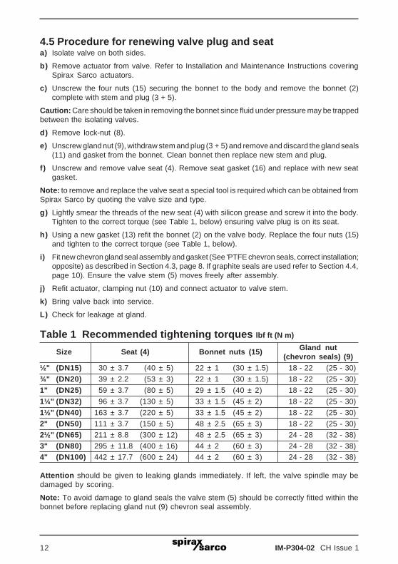
4.5 Procedure for renewing valve plug and seata) Isolate valve on both sides.
b) Remove actuator from valve. Refer to Installation and Maintenance Instructions coveringSpirax Sarco actuators.
c) Unscrew the four nuts (15) securing the bonnet to the body and remove the bonnet (2)complete with stem and plug (3 + 5).
Caution: Care should be taken in removing the bonnet since fluid under pressure may be trappedbetween the isolating valves.
d) Remove lock-nut (8).
e) Unscrew gland nut (9), withdraw stem and plug (3 + 5) and remove and discard the gland seals(11) and gasket from the bonnet. Clean bonnet then replace new stem and plug.
f) Unscrew and remove valve seat (4). Remove seat gasket (16) and replace with new seatgasket.
Note: to remove and replace the valve seat a special tool is required which can be obtained fromSpirax Sarco by quoting the valve size and type.
g) Lightly smear the threads of the new seat (4) with silicon grease and screw it into the body.Tighten to the correct torque (see Table 1, below) ensuring valve plug is on its seat.
h) Using a new gasket (13) refit the bonnet (2) on the valve body. Replace the four nuts (15)and tighten to the correct torque (see Table 1, below).
i) Fit new chevron gland seal assembly and gasket (See 'PTFE chevron seals, correct installation;opposite) as described in Section 4.3, page 8. If graphite seals are used refer to Section 4.4,page 10). Ensure the valve stem (5) moves freely after assembly.
j) Refit actuator, clamping nut (10) and connect actuator to valve stem.
k) Bring valve back into service.
L) Check for leakage at gland.
Table 1 Recommended tightening torques lbf ft (N m)
Size Seat (4) Bonnet nuts (15) Gland nut(chevron seals) (9)
½" (DN15) 30 ± 3.7 (40 ± 5) 22 ± 1 (30 ± 1.5) 18 - 22 (25 - 30)
¾" (DN20) 39 ± 2.2 (53 ± 3) 22 ± 1 (30 ± 1.5) 18 - 22 (25 - 30)
1" (DN25) 59 ± 3.7 (80 ± 5) 29 ± 1.5 (40 ± 2) 18 - 22 (25 - 30)
1¼" (DN32) 96 ± 3.7 (130 ± 5) 33 ± 1.5 (45 ± 2) 18 - 22 (25 - 30)
1½" (DN40) 163 ± 3.7 (220 ± 5) 33 ± 1.5 (45 ± 2) 18 - 22 (25 - 30)
2" (DN50) 111 ± 3.7 (150 ± 5) 48 ± 2.5 (65 ± 3) 18 - 22 (25 - 30)
2½" (DN65) 211 ± 8.8 (300 ± 12) 48 ± 2.5 (65 ± 3) 24 - 28 (32 - 38)
3" (DN80) 295 ± 11.8 (400 ± 16) 44 ± 2 (60 ± 3) 24 - 28 (32 - 38)
4" (DN100) 442 ± 17.7 (600 ± 24) 44 ± 2 (60 ± 3) 24 - 28 (32 - 38)
Attention should be given to leaking glands immediately. If left, the valve spindle may bedamaged by scoring.
Note: To avoid damage to gland seals the valve stem (5) should be correctly fitted within thebonnet before replacing gland nut (9) chevron seal assembly.
3

IM-P304-02 CH Issue 1 13
5
1
2
9
15 5
11
13
16
3
10
8
4
17
14
7
18
1
6
½" to 2½"(DN15 to DN65)
12
3
PTFE chevron sealscorrect installation
9
7164
6
Plug and seat3" and 4" (DN80 and DN100)

IM-P304-02 CH Issue 114
5. SparesNote: When placing an order for spares please indicate clearly the product date code (found onthe label of the valve body i.e. F9) to ensure that the order is processed quickly, efficiently andcorrectly.
Spare partsThe spare parts available are in heavy outline. Parts drawn in broken line are not supplied asspares. These spares are for sizes ½" to 4" (DN15 to DN100).
Available spareActuator clamping nut A
Gland seal kit (spring, chevrons and gasket) B
Graphite gland seal kit (seal rings, support rings) C
Stem, plug and bonnet gasket D, E
Bonnet gasket (packet of 3) E
Seat, seat gasket and bonnet gasket F, G, E
How to order sparesAlways order spares by using the description given in the column headed 'Available spare', statingthe following information and the date code of the product.
Valve size ½" to 4"(DN15 to DN100)
Valve series L series - 2 port
Valve characteristic E = Equal percentageF = Fast opening
Design series A = ANSI /ASTM
Body material 3 = Cast iron
Connections 1 = Screwed NPT3 = Flanged ANSI 125
Stem sealing option H = High temperature packing
Sealing option G = Soft seal (PTFE)
Cv To be specified
Connection type To be specified
Date code Found on the label of the valve body
1" L E A 3 3 Cv 11.7 ANSI 125 Date coded F9
Example: 1 - Gland seal kit for 1" LEA33 Cv 11.7 flanged to ANSI 125. Date code F9.
1"
L
E
A
3
3
Cv 11.7
ANSI 125
F9

IM-P304-02 CH Issue 1 15
C B
Valve sizes3" and 4"
(DN80 and DN100)
D
F
G
E
Valve sizes½" to 2½"
(DN15 to DN65)
D
F
G
Actuatorclamping nut (A)
Date code location
A½" to 2"
(DN15 to DN50)
A2½" to 4"(DN65 toDN100)

IM-P304-02 CH Issue 116