1-s2.0-s0196890413006687-main
DESCRIPTION
ggiiTRANSCRIPT
Energy Conversion and Management 77 (2014) 527–534
Contents lists available at ScienceDirect
Energy Conversion and Management
journal homepage: www.elsevier .com/ locate /enconman
Efficiencies and improvement potential of building integratedphotovoltaic thermal (BIPVT) system
0196-8904/$ - see front matter � 2013 Elsevier Ltd. All rights reserved.http://dx.doi.org/10.1016/j.enconman.2013.10.033
⇑ Corresponding author.E-mail address: [email protected] (A. Fudholi).
Adnan Ibrahim a, Ahmad Fudholi b,⇑, Kamaruzzaman Sopian b, Mohd Yusof Othman b,Mohd Hafidz Ruslan b
a Universiti Kuala Lumpur Institute of Product Design and Manufacturing (UniKL IPROM), 56100 Cheras, Kuala Lumpur, Malaysiab Solar Energy Research Institute, Universiti Kebangsaan Malaysia, 43600 Bangi, Selangor, Malaysia
a r t i c l e i n f o
Article history:Received 26 June 2013Accepted 10 October 2013
Keywords:BIPVT systemEnergy analysisExergy analysisPrimary-energy saving efficiencyImprovement potential
a b s t r a c t
Building integrated photovoltaic thermal (BIPVT) system has been designed to produce both electricityand hot water and later integrated to building. The hot water is produced at the useful temperaturesfor the applications in Malaysia such as building integrated heating system and domestic hot water sys-tem as well as many industrial including agricultural and commercial applications. The photovoltaic ther-mal (PVT) system comprises of a high efficiency multicrystal photovoltaic (PV) module and spiral flowabsorber for BIPVT application, have been performed and investigated. In this study, it was assumed thatthe absorber was attached underneath the flat plate single glazing sheet of polycrystalline silicon PVmodule and water has been used as a heat transfer medium in absorber. Performances analysis of BIPVTsystem based on energy and exergy analyses. It was based on efficiencies including energy and exergy,and exergetic improvement potential (IP) based on the metrological condition of Malaysia has been car-ried out. Results show that the hourly variation for BIPVT system, the PVT energy efficiency of 55–62% ishigher than the PVT exergy efficiency of 12–14%. The improvement potential increases with increasingsolar radiation, it is between 98 and 404 W. On the other hand, BIPVT system was produced primary-energy saving efficiency from about 73% to 81%.
� 2013 Elsevier Ltd. All rights reserved.
1. Introduction
The last few years have seen the development of renewableenergy (RE) systems based mainly on wind and solar energy [1].Presently, research and development programmes in developingcountries are oriented towards the applications of solar energyfor domestic hot water systems, solar distillation of sea andbrackish water, water pumping, drying of agricultural produce,solar industrial process heat, and photovoltaic (PV) for remoteapplications. However, in developed countries extensive workhave been carried out on space heating and cooling (passive andactive design), building integrated photovoltaic (BIPV) systemsand products, grid connected RE system including biomass andPV system, daylighting, solar thermal electricity generation, andsolar refrigeration [2]. A new hybrid geothermal and solar drivenabsorption cooling system was proposed for low-temperaturedistrict energy applications [3].
Many researches towards the solar energy occur all over theword to the concern of global crisis on oil and gas prices. Accordingto some experts, oil has ready started to peak. Gas and coal
reserves are bigger than oil, will tend to be progressively replacedby the former, which should attenuate a price explosion. Neverthe-less this process will push energy prices higher, until sustainablesources replace dependency on fossil fuels as major source ofenergy. The sustainable energy such as solar energy has been iden-tified as one of the promising source of energy to replace thedependency on fossil fuels. Solar energy is a clean energy whichhas the potential to meet a significant proportional of the world’senergy needs. It can be broadly classified into two systems; PV en-ergy system which converts solar energy into electrical energy, andthermal energy system which converts solar energy into thermalenergy. The inspiration of combining PV and solar collector to pro-vide electrical and heat energy is not new, however it is an areathat has received only limited attention. With concern growingover energy sources and their usage, PVT has become an areawhich is receiving much more attention. PVT systems convert solarradiation directly to both electrical and thermal energies. A PVTsystem basically combines the functions of a flat plate solar collec-tor and those of a photovoltaic (PV) panel. Innovative applicationsof PVT system were performed recently [4–10].
The research on PVT started during the mid-1970s, with thefocus on PVT systems, and the main aim with increase of the PVefficiency. Domestic application was regarded as the main market.

Nomenclature
Ac frontal area solar collector (m2)b collector width (m)Cb conductance of the bond between the fin and square
tubeCp specific heat of working fluid (J/kg �C)D diameter (m)Dh hydraulic diameter (m)F fin efficiency factorF0 collector efficiency factorFR heat removal efficiency factorGT solar radiation at NOCT (W/m2)hfi heat transfer coefficient of fluid (W/m2 �C)k thermal conductivity (W/m �C)L tube length (m)l thickness (m)_m mass flow rate (kg/s)
N number of glass covern number of tubep collector perimeter (m)Qu useful thermal energy (W)S solar radiation (W/m2)T temperature (�C)UL overall heat transfer coefficient (W/m2 �C)Ut top loss coefficient (W/m2 �C)
m wind velocity (m/s)W tube spacing (m)a absorptanceh collector tilte emittances transmittanceg efficiencyr Stefan’s Boltzmann constant (W/m2 �C4)
Subscriptsa ambientabs absorber thicknessc cellfi inlet fluidg glassi inleto outletp platepm mean platePV photovoltaicPVT photovoltaic thermalr referencet tubew wind
528 A. Ibrahim et al. / Energy Conversion and Management 77 (2014) 527–534
Initially the focus was on glazed collectors, both air based andwater based. Due to these problems, the cost for a complete systemof PVT is incredibly high and unaffordable to the industrial and res-idential owners. One of the most attractive application of PVT air orwater based collectors are building integrated photovoltaic ther-mal (BIPVT) which has undergone rapid developments in recentyears. BIPVT system is a promising system to generate both ener-gies due to its higher reliability system with lower environmentimpact. Generally, the BIPVT system consists of the PV module,absorber in the formed of tubes, the glass cover (transparent)and insulated container. It is expected that over the next few years,there will be a rapid growth in BIPVT publications and products[11–13].
Several studies on BIPVT systems have been conducted. It wastheoretically analyzed based on modified Hottel–Whillier modeland was validated with experimental data from testing on a proto-type BIPVT system [14]. The importance of influence of designparameters such as the fin efficiency, the thermal conductivitybetween the PV cells and their supporting structure, and the lam-ination method on both the electrical and thermal efficiency of theBIPVT remarked. Furthermore, it was shown that the BIPVT couldbe made of lower cost materials, such as pre-coated colour steel,without significant decreases in efficiency. It was also concludedthat integration of BIPVT into the building rather than onto thebuilding could results in a lower cost system. In one research workon water-based BIPVT system, a numerical model of wall-mountedwater-based PVT systems were developed by modifying the Hot-tel–Whillier model, which was originally for the thermal analysisof flat-plate solar thermal collectors.
A dynamic simulation model on a water-based BIPVT systemintroduced and the validity of this modeling approach was demon-strated through comparison with experimental data [15]. The re-sults depicted that other than the electrical performance hasbeen affected by the on-site shading problem, the output fromthe model showed good compliance with the experimentalobservations.
A computer simulation with energy models developed forwater-based BIPVT system. Higher economical advantages in com-parison with conventional PV system obtained. The year-averagethermal and cell conversion efficiencies for a specific BIPVT systemat a vertical wall of a fully air-conditioned building and with collec-tors equipped with flat-box-type thermal absorber and polycrys-talline silicon cell were respectively 37.5% and 9.39% comparedwith the normal building façade [16].
A computational fluid dynamic (CFD) model for a novel BIPVTsystem was developed and validated it experimentally [17]. The re-sult indicated that PV cell efficiency can be raised up to 5.3% andthe outlet water temperature of collector was suitable for domestichot water use. Effect of flow distribution on the PV performance ofa water-based BIPVT system was investigated [18]. The resultsshown that parameters including the manifold to riser pipe ratio,array geometry, manifold flow direction, and mass flow rate tohave an influence on flow distribution and therefore PV conversion.
Recently, performance analysis has been carried out exergyanalysis on BIPVT system. Performance analysis and life cycle costwere evaluated for the BIPVT systems with different PV technologycompared with the similar BIPVT system. The results show that theuse of BIPVT systems was always advantageous both from the effi-ciency and the economic point of view than similar BIPVT systems.The mono-crystalline silicon BIPVT systems have higher energyand exergy efficiencies and were suitable where energy and exergydemands were higher and space for mounting such systems werelimited, like multi-storey buildings [19].
BIPVT applications are among the cost effective solar energyapplications, however, a lot of research works still need to be doneand one of the most important part of research and developmentworks in this area should be allocated to design of new thermal ab-sorber collectors. New design of BIPVT system is presented in thispaper. Prototype of this new absorber is constructed. Since fewstudies of water-based BIPVT systems have been conducted tillnow, therefore further experimental and analytical study shouldbe carried out aiming at incrementing our knowledge regarding

Fig. 1. Spiral flow absorber.
Fig. 3. Photograph of BIPVT system.
A. Ibrahim et al. / Energy Conversion and Management 77 (2014) 527–534 529
improving electrical and thermal performance of BIPVT systembased on the energy and exergy analyses.
2. Material and method
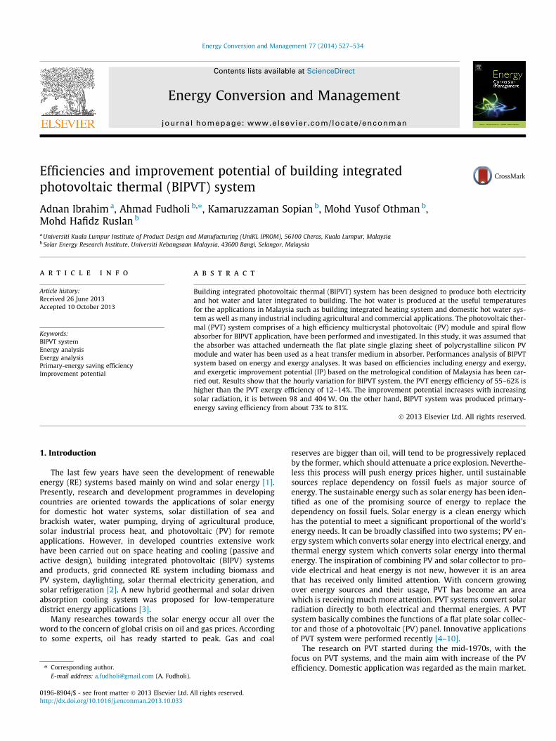
Fig. 1 shows the spiral flow absorber of water-based BIPVTsystem. The tube design is the simplest and easiest to be manufac-tured, even though, the efficiency is 2% lower compared to othertypes of absorbers such as, channel, free flow and two-absorber[13]. The spiral flow absorber was made of rectangular hollowtubes of stainless steel material with dimension of 12.7 �12.7 mm. The tube was connected using a welding method. The ab-sorber, as shown in Fig. 2 consist of a single unilateral channel forthe water to flow in it with the size of 815 � 628 � 30 mm before itwas inserted underneath the standard photovoltaic panel with thesize of 1 m height, 0.65 m length and 0.3 m thickness. Thermalinsulator was packed underneath the absorber to prevent heatfrom escaping further and provides more uniform temperaturesthroughout the system. A standard PV panel represented as a flatplate single glazing sheet of polycrystalline silicon with single glaz-ing sheet has been used. The spiral flow absorber was designed inthe form of continuous coil or tube configured. The spiral coil hasat least one inlet and outlet to allow medium (water) to enterand to exit from coil respectively. The inlet and the outlet of thespiral coil were arranged further away to the enter point of thespiral. This will allow the medium (water) to flow in reverseddirection and covered the entire PV panel. The configuration: med-ium (water) with lower temperature enters the coil and flow intothe centre point and flow out from the centre point leaving the coilas hot water. The hot water can be consumed or stored for lateruse. In this way solar radiation energy can be fully utilized. In thisexperiment, standard PV panel, rating at 80 W powers was used. Asshown in Fig. 3, the spiral flow absorber was inserted underneaththe standard PV panel and tested outdoor. As shown in Fig. 4,ambient temperature and other temperatures were measuredusing K-type thermocouple and located at several places. Solarradiations from the sun were measured by Eppley pyranometer.Mass flow rate for spiral flow absorber was set of 0.027 kg/s andconnected direct to data acquisition system which later link tothe computer. Data collected and stored in the ADAM Data Acqui-sition System for every 1 min and later used to calculate the perfor-
Fig. 2. The assembly view of spiral flow absorber.
mances of BIPVT system. The analytical parameters of the BIPVTsystem were presented in Table 1.
3. Energy analysis
The performance of PVT systems can be depicted by the combi-nation of efficiency expression [20]. It comprised of the thermalefficiency (gth) and the electrical efficiency (gPV). These efficienciesusually include the ratio of the useful thermal gain and electricalgain of the system to the incident solar irradiation on the collec-tor’s gap within a specific time or period. The analytical parametersof the PVT system are presented in Table 2. The total of the efficien-cies, which is known as total efficiency or PVT efficiency (gPVT) isused to evaluate the overall performance of the system [20–22]:
gPVT ¼ gth þ gPV ð1Þ
Considering that electrical energy (gf) is a high-grade form ofenergy gain, primary energy saving efficiency is proposed as an-other performance evaluation method to recognize the energygrade difference between electricity and thermal, which is givenby [20–22]
gf ¼gPV
gpþ gth ð2Þ
where gp is the electric-power generation efficiency of the conven-tional power plant, its value can be taken as 38%. The evaluationindicator of primary-energy saving efficiency concerns both of thequality and quantity of the energy that the PVT system converts so-lar energy too.
3.1. Energy analysis of flat plate PVT system
The thermal performance of the PVT is affected by many systemdesign parameters and operating conditions. In this study, the sys-tem is analyzed with various configurations of solar radiation,ambient temperature, and flow rate conditions. The collector is as-sumed to be represented as a flat plate collector with single glazingsheet. Based on this assumption, the thermal performance of thePVT unit is evaluated for its thermal and photovoltaic performance,as such, the derivation of the efficiency parameters based on theHottel–Whillier equations were used [23]. The thermal efficiencyof the conventional flat plate solar collector is a ratio of the usefulthermal energy (Qu) to the overall incident solar radiation (S), andcan be written as:
gth ¼Q u
Sð3Þ
Fig. 4. The schematic diagram of experimental setup.
Table 1BIPVT system characteristics.
Description Symbol Value Unit
Ambient temperature Ta 20 �CCollector area Ac 0.65 m2
Number of glass cover N 1Emittance of glass eg 0.88Emittance of plate ep 0.95Collector tilt h 14 �Fluid thermal conductivity kf 0.613 W/m �CSpecific heat of working fluid Cp 4180 J/kg �CBack insulation conductivity kb 0.045 W/m �CBack insulation thickness lb 0.05 mInsulation conductivity ke 0.045 W/m �CEdge insulation thickness le 0.025 mAbsorber conductivity kabs 51 W/m �CAbsorber thickness labs 0.002 mFin conductivity kf 84 W/m �CFin thickness d 0.0005 mHeat transfer coefficient from
cell to absorberhca 45 W/m �C
Heat transfer inside tube hfi 333 W/m �CTransmittance s 0.88Absorptance a 0.95
Table 2The comparison present study with other absorber designs [21,35–39].
Performance from energy analysis References
gPV = 9.5%, gth = 50%, gPVT = 59.5% [21]gPV = 9%, gth = 38%, gPVT = 47% [35]gPVT = 65% at 0 �C operation temperature [36]gPV = 11%, gth = 51%, gPVT = 62% [37]gf = 64.9%gPV = 9.87%, gth = 40%, gPVT = 49.87% [38]gPV = 10.15%, gth = 45%, gPVT = 55.15% [39]gPV = 11.4–11.3%, gth = 45–51%, gPVT = 55–62%gf = 73–81% Present study
530 A. Ibrahim et al. / Energy Conversion and Management 77 (2014) 527–534
The useful collected heat gain by the flat plate solar collector couldeither be given as the coupling results of average mass flow rateð _mÞ, heat capacity of flowing medium (Cp) and temperature differ-ence at the collector inlet (Ti) and outlet (To), can be written as:
Q u ¼ _mCpðTo � TiÞ ð4Þ
The difference between the absorber solar radiation and thermalheat losses is identified by Hottel–Whillier equations [24]:
Qu ¼ AcFR½GTðsaÞPV � ULðTi � TaÞ� ð5Þ
where Ac is the collector area, Ta is ambient temperature, Ti is inlettemperature, UL is overall collector heat loss, (sa)PV is PV thermalefficiency, GT is solar radiation at NOCT (radiation level 800 W/m2,wind velocity 1 m/s and ambient temperature at 26 �C) and FR isheat removal efficiency factor introduced [23,24]:
FR ¼_mCp
AcUL1� exp �AcULF 0
_mCp
� �� �ð6Þ
where F0 is collector efficiency factor, which calculated using:
F 0 ¼1
UL
ULðDh þ ðW � DhÞFÞ
" #þ 1
Cbþ 1
2ðaþ bÞhfið7Þ
where a is width of the duct, b is height of the duct, Cb is conduc-tance of the bond between the fin and square tube, hfi is heat trans-fer coefficient of fluid, Dh is hydraulic diameter and F is fin efficiencyfactor, given by:
F ¼tanh M W�Dh
2
� �ffiffiffiffiffiffiffiffiffiffiffiffiffiffiffiM W�Dh
2
q ð8Þ
where
Dh ¼2abðaþ bÞ ð9Þ
The coefficient M of Eq. (8) is a term which takes into account boththe thermal conductivity of the absorber and the PV cell calculatedby [18,25]
M ¼
ffiffiffiffiffiffiffiffiffiffiffiffiffiffiffiffiffiffiffiffiffiffiffiffiffiffiUL
kabslabskPV lPV
sð10Þ
where kabs is absorber thermal conductivity, labs is absorber thick-ness, kPV is PVT conductivity, and lPV is PV collector thickness. Thecollector overall loss coefficient (UL) is the sum of the edge (Ue)and top (Ut) loss coefficients, can be written as:
UL ¼ Ue þ Ut ð11Þ
Ue ¼keplLeAc
ð12Þ

A. Ibrahim et al. / Energy Conversion and Management 77 (2014) 527–534 531
Ut ¼N
CTpm
Tpm�Ta
ðNþf Þ
h ie1
hw
8><>:
9>=>;�1
þrðTpm þ TaÞ T2
pm þ T2a
� �ðep þ 0:00591NhwÞ�1 þ 2Nþf�1þ0:133ep
eg� N
ð13Þ
where
C ¼ 520ð1� 0:000051b2Þ ð14Þ
f ¼ ð1þ 0:089hw � 0:1166hwepÞð1þ 0:07866NÞ ð15Þ
e ¼ 0:43 1� 100Tpm
� �ð16Þ
Tpm ¼ Ti þQ=Ac
FRULð1� FRÞ ð17Þ
where p is the collector perimeter, N is number of glass covers, r isStefan–Booltzmann constant, ep is emittance of plate, eg is emittanceof glass, b is collector tilt, Tpm is mean plate temperature and hw iswind heat transfer coefficient.
The heat transfer coefficients, such as for forced convection (hw)can be calculated by [26] and natural heat transfer (hnat) can be cal-culated by [26]:
hw ¼ 2:8þ 3:0v ð18Þ
hnat ¼ 1:78ðTpm � TaÞ ð19Þ
By combining the natural and forced convection heat transfer (Eqs.(18) and (19)) enable to determine the overall convection heattransfer (hc) and at the same time possible to determine the overalltop loss heat transfer coefficient for the collector [27].
hc ¼ffiffiffiffiffiffiffiffiffiffiffiffiffiffiffiffiffiffiffih3
w þ h3nat
qð20Þ
Referring from the Eqs. (3)–(20), it is then possible to calculatethe useful heat gain produced by the PVT system. By rearrangingEq. (3), the thermal efficiency of the collector is expressed as [28]
gth ¼ FRðsaÞPV � FRULTi � Ta
S
� �ð21Þ
3.2. Theory of PV module
Electrical efficiency of the PV module (gPV), which is a functionof module temperature given by [11,29]
gPV ¼ grð1� cðTc � TrÞÞ ð22Þ
where gr is reference efficiency of PV module (gr = 0.12), c is tem-perature coefficient (c = 0.0045 �C), Tc is cell temperature and Tr isreference temperature.
4. Exergy analysis
Energy analysis is based on the first law of thermodynamics.Exergy analysis is based on the second of law of thermodynamics,which if the effects due to the kinetic and potential energy changesare neglected, the general exergy balance can be expressed in rateform as given [30,31].X
Exin �X
Exo ¼X
Exd ð23Þ
orXExin �
XðExth þ ExPV Þ ¼
XExd ð24Þ
where
Exin ¼ AcNcS 1� 43
Ta
Tsþ 1
3Ta
Ts
� �4 !" #
ð25Þ
Exth ¼ Qu 1� Ta þ 273To þ 273
� �ð26Þ
ExPV ¼ gcAcNcS 1� 43
Ta
Tsþ 1
3Ta
Ts
� �4 !" #
ð27Þ
ExPVT ¼ Exth þ ExPV ð28Þ
where Exin is input exergy (radiation exergy), Exo is output exergy,Exth is thermal exergy, ExPVT is photovoltaic thermal exergy, Ac iscollector area, Nc is collectors number, S is solar radiation, Ta isambient temperature and Ts is sun temperature (Ts = 5777 K). Theexergy destruction ð _ExdÞ or irreversibility may be expressed as[32,33]
Exd ¼ TaSgen ð29Þ
where Sgen is entropy generation rate. While the irreversibility ofany energy process is at minimum, the improvement in the exergyefficiency is at maximum. The concept of an exergetic ‘‘improve-ment potential’’ (IP) could be considered as a very useful tool toanalyzing systems or process more efficiently. The IP of a systemor process is given by [33,34].
IP ¼ ð1� gexÞ _Exd ð30Þ
where gex is the second law efficiency may be expressed as
gex ¼ 1� Exd
Exinð31Þ
5. Results and observations
Characteristic of warm-humid equatorial climate like in Malay-sia vary significantly throughout the day. This is mainly due to theformation of clouds creating sky patches and resulting in obstruc-tion of the sun. Therefore the solar radiation penetration is not con-stant and the intensity of the solar radiation from the sky vaults isa combination of direct sun, clear sky portion and from the cloudyportion. The annual average daily solar radiation in Malaysia is 4–5 kW h/m2 with the monthly average daily sunshine durationranging from 4 to 5 h [11]. Fig. 5 shows the hourly average varia-tion of solar radiation and ambient temperature for a typical dayin the middle of December 2010 for Malaysia. Fig. 5 shows the var-iation of PV temperatures versus the time. The PV temperature andoutlet temperature steadily increases with time and solar radia-tion. As the solar radiation decreases; the rate of increasing in tem-perature of PV and outlet temperature also decreases. A maximumpredicted PV temperature of 54 �C, and 49 �C for outlet tempera-ture are obtained.
Referring to Fig. 5, the daily mean values of ambient tempera-ture, outlet temperature and solar radiation varied from approxi-mately 29 to 37 �C, 33–49 �C, and 490–890 W/m2 respectively,with their corresponding average values being 34 �C, 43 �C and690 W/m2 respectively. The PV, thermal and PVT energy variedcontinuously with increasing solar radiation and time. The results,the PV, thermal and PVT energy useful of BIPVT system varied from34 to 60 W, 220–435 W and 254–495 W respectively at mass flowrate of 0.027 kg/s.
Hence the energy that arrived at the heat absorber through thePV module was reduced due to decreasing of solar radiation; thislowered the heat gain of water at the absorber, therefore the water

Fig. 5. Average hourly radiation, temperatures and performances with time.
Fig. 7. Variation of thermal and PVT efficiencies as a function of the ratio (Ti � Ta)/S.
532 A. Ibrahim et al. / Energy Conversion and Management 77 (2014) 527–534
temperature decreased. Fig. 6 shows the PV efficiency declines asPV temperature rise. The PV efficiency is between 10.4% and11.3%. In determining efficiency of the BIPVT system, the effective-ness can be represented by an efficiency curve, which indicates theefficiency versus the reduced temperature parameters or (Ti � Ta)/S. Thermal and PVT efficiencies as function of ratio of (Ti � Ta)/S areshown in Fig. 7. The efficiency curve decreases as the (Ti � Ta)/S in-crease. The thermal and PVT energy efficiencies of BIPVT systemare ranging from 44% to 51% and 55–62% respectively, as shownin Fig. 7.
The performance of BIPVT systems can be depicted by the com-bination of efficiency expression. It comprised of the electrical effi-ciency and thermal efficiency. The total of the both efficiencies,which is known as PVT efficiency is used to evaluate the overallperformance of the system. Table 2 shows the summarized of com-parison present study with other absorber designs [35–39]. Theymanaged to achieve the PV efficiency of 10.15% with 45% thermalefficiency in total efficiency of 55.15%. Referring to [21], PVT waterbased collector can achieve maximum electrical efficiency ofaround 9.5% and thermal efficiency of about 50%. They have com-pared the conventional solar water heater the PVT system knowsas integrated photovoltaic/thermal system (IPV/TS). They con-cluded that the solar PVT system made from corrugated polycar-bonate module produced good thermal efficiency. They suggestedthat further improvement could be achieved by proper insulationfor the PVT design. They managed to achieve the PV efficiency of9% with 38% thermal efficiency in total efficiency (PVT efficiency)of 47%.
An experiment of PVT system for domestic application in Chinahas been conducted [36,37]. In this experiment, an aluminium-al-loy flat box with square or rectangular shape channel has been de-signed and constructed. The test results shows high efficiency oncombined system achieved with primary energy saving for dailyexposure approaches 65% at zero reduced temperature operation.
Fig. 6. PV efficiency as a function of PV temperature.
They managed to achieve the PV efficiency of 11% with 51% ther-mal efficiency in total efficiency (PVT efficiency) of 62%. Similarexperiment has been performed using an aluminium-alloy flatbox, with square or rectangular shape channel together with poly-crystalline silicone cells utilized water as coolant for cooling pur-poses [38]. They conclude that the thermal efficiency reachedaround 40% when the initial temperature in the system is sameas the daily mean ambient temperature. They managed to achievethe PV efficiency of 9.87% with 40% thermal efficiency in total effi-ciency of 49.87%.
Another experiment on natural circulation hybrid PVT waterheating system has been studied [39]. In this experiment, sensitiv-ity study of the system has been performed and proved that bycombining the system, the installation area produce more energyper unit surface area than one PV module and one hot watersystem.
Fig. 8 shows the hourly variation of PV, thermal, PVT and pri-mary-energy saving efficiencies for BIPVT system with spiral flowabsorber at mass flow rate of 0.027 kg/s. The collector were pro-duced PVT efficiency of 55–62% with 10.4–11.3% PV efficiencyand of 45–51% thermal efficiency, also it produced primary-energysaving efficiency from about 73% to 81%.
Fig. 9 shows the hourly variation of solar radiation and exergiesof the BIPVT system with spiral flow absorber. In Fig. 9 clearlyshows that PV, thermal and PVT exergy increase as the solar radi-ation increases. The PVT exergy is between 37 W and 71 W withthermal exergy of 3–15 W, and electrical exergy of 34–56 W. Thedestruction and input exergies varied from 257 to 466 W and297–537 W respectively at mass flow rate of 0.027 kg/s.
Fig. 10 shows the hourly variation of outlet temperature, energyand exergy efficiencies. It is found that outlet temperature of col-lector increased with increased time until at 14.5 p.m with the out-let temperature is between 33 and 49 �C. On the other, the PVTenergy efficiency of 55–62% is higher than the PVT exergy effi-ciency of 12–14%. Maximum PVT exergy efficiency of 14% can beseen at 15–16.5 p.m. whereas minimum PVT exergy efficiency of12% is seen at 10.5 a.m. Fig. 11 clearly shows that the improvementpotential increase as the solar radiation increases. The improve-ment potential is between 98 and 404 W. Table 3 shows the exergy
Fig. 8. Changes of efficiencies for BIPVT system over time at mass flow rates of0.027 kg/s.

Fig. 9. Changes solar radiation and exergies of BIPVT system over time at mass flowrates of 0.027 kg/s.
Fig. 10. Changes of energy and exergy efficiencies and outlet temperature over timeat mass flow rate of 0.027 kg/s.
Fig. 11. Variation of improvement potential as a function of solar radiation.
Table 3The comparison present study (exergy efficiency) with other PV/T systems [40,41].
PV/T system Exergyefficiency (%)
The glazed water-based PVT systems [40] 8–13.30The coverless water-based PVT system [40] 11–12.87The unglazed air-based PVT system [40] 10.75The (glass-to-glass) air-based PVT system [40] 10.45The unglazed air-based PVT integrated greenhouse with
earth air heat exchanger [40]5.50
The unglazed air-based PVT integrated greenhouse [40] 4The PV array [40] 3–9The PV system [41] 3.65–11.34
(Classical)2.51–10.92(New)
Present study 12.29–13.79
A. Ibrahim et al. / Energy Conversion and Management 77 (2014) 527–534 533
efficiency of PV/T system under study [40]. Also, Table 3 shows thePV exergy efficiency compared with a novel approach for estima-tion PV exergy efficiency in exergy analyses [41].
6. Conclusion
The BIPVT system comprises of a combined PV module and spir-al flow absorber has been investigated. The PV temperature in-creases when it absorbs solar radiation, causing a decrease inefficiency. From energy analysis at a mass flow rate of 0.027 kg/sand average solar radiation of 690 W/m2, the average PV, thermaland PVT energy efficiencies were 10.8%, 48% and 59%, respectively.Moreover from exergy analysis, the PVT exergy efficiency andimprovement potential were 13.1% and 314 W. In this study, itwas found that the PVT energy efficiency varies between 55% and62% where as the variation in the PVT exergy efficiency is from12% to 14%. The improvement potential increases with increasingsolar radiation. The improvement potential is between 98 and404 W.
Acknowledgements
The authors would like to thank the Ministry of Science, Tech-nology and Innovation Malaysia for funding this research (Science-fund 03-01-02-SF0039) and the Solar Energy Research Institute(SERI), University Kebangsaan Malaysia for providing the labora-tory facilities and technical support.
References
[1] Sopian K, Ibrahim MZ, Daud WRW, Othman MY, Yatim B, Amin N. Performanceof a PV-wind hybrid system for hydrogen production. Renew Energy2009;34:1973–8.
[2] Sopian K, Shaari S, Amin N, Zulkifli R, Rahman MNA. Performance of a grid-connected photovoltaic system in Malaysia. Int J Eng Technol2007;4(1):57–65.
[3] Coskun C, Oktay Z, Dincer I. Investigation of a hybrid solar and geothermaldriven absorption cooling system for district applications. Int J Exergy2012;11(2):205–15.
[4] Ammar MB, Chaabene M, Chtourou Z. Artificial neural network based controlfor PV/T panel to track optimum thermal and electrical power. Energy ConversManage 2013;65:372–80.
[5] Kandilli C. Performance analysis of a novel concentrating photovoltaiccombined system. Energy Convers Manage 2013;67:186–96.
[6] Calise F, Dentice d’Accadia M, Vanoli L. Design and dynamic simulation of anovel solar trigeneration system based on hybrid photovoltaic/thermalcollector (PVT). Energy Convers Manage 2012;60:214–25.
[7] Gang P, Huide F, Jie J, Tin-tai C, Tao Z. Annual analysis of heat pipe PV/T systemfor domestic hot water and electricity production. Energy Convers Manage2012;56:8–21.
[8] Zhao J, Song Y, Lam WH, Liu W, Liu Y, Zang Y, et al. Solar radiation transfer andperformance analysis of an optimum photovoltaic/thermal system. EnergyConvers Manage 2011;52:1343–53.
[9] Chemisana D, Ibanez M, Rosell JI. Characterization of a photovoltaic–thermalmodule for Fresnel linear concentrator. Energy Convers Manage2011;52:3234–40.
[10] Li M, Li GL, Ji X, Yin F, Xu L. The performance analysis of the troughconcentrating solar photovoltaic/thermal system. Energy Convers Manage2011;52:2378–83.
[11] Daghigh R, Ibrahim A, Jin GL, Ruslan MH, Sopian K. Predicting the performanceof amorphous and crystalline silicon based photovoltaic solar thermalcollectors. Energy Convers Manage 2011;52:1741–7.
[12] Touafek K, Haddadi M, Malek A. Design and modeling of a photovoltaicthermal collector for domestic air heating and electricity production. EnergyBuild 2013;59:21–8.
[13] Ibrahim A, Othman MY, Ruslan MH, Mat S, Sopian K. Recent advances in flatplate photovoltaic/thermal (PV/T) solar collectors. Renew Sustain Energy Rev2011;15:352–65.
[14] Anderson TN, Duke M, Morrison GL, Carson JK. Performance of a buildingintegrated photovoltaic/thermal (BIPVT) solar collector. Solar Energy2009;83:445–55.
[15] Chow TT, He W, Chan ALS, Fong KF, Lin Z, Ji J. Computer modeling andexperimental validation of a building-integrated photovoltaic and waterheating system. Appl Therm Eng 2008;28:1356–64.
[16] Chow TT, Chan ALS, Fong KF, Lin Z, He W, Ji J. Annual performance of building-integrated photovoltaic/water-heating system for warm climate application.Appl Energy 2009;86:689–96.

534 A. Ibrahim et al. / Energy Conversion and Management 77 (2014) 527–534
[17] Corbin CD, Zhai ZJ. Experimental and numerical investigation on thermal andelectrical performance of a building integrated photovoltaic–thermal collectorsystem. Energy Build 2010;42:76–82.
[18] Ghani F, Duke M, Carson JK. Effect of flow distribution on the photovoltaic/thermal (BIPV/T) collector. Solar Energy 2012;86:1518–30.
[19] Agrawal B, Tiwari GN. Life cycle cost assessment of building integratedphotovoltaic thermal (BIPVT) systems. Energy Build 2010;42:1472–81.
[20] He W, Zhang Y, Ji J. Comparative experiment study on photovoltaic andthermal solar system under natural circulation of water. Appl Therm Eng2011;31:3369–76.
[21] Zhang X, Zhao X, Smith S, Xu J, Yu X. Review of R&D progress and practicalapplication of the solar photovoltaic/thermal (PV/T) technologies. RenewSustain Energy Rev 2012;16:599–617.
[22] Radziemska E. Performance analysis of a photovoltaic–thermal integratedsystem. Int J Photoenergy 2009:1–6.
[23] Hottel HC, Whillier A. Evaluation of flat-plate solar collector performance, In:Perform Trans Conf Solar Energy. Tucson, Arizona; 1958. p. 74.
[24] Duffie JA, Beckman WA. Solar engineering of thermal processes. 2nd ed. NewYork: John Willey and Sons Inc; 1958.
[25] Zondag HA, Vries DW, Van Steenhoven AA, Zolingen RJC. The thermal andelectrical yield of a PV–thermal collector. Solar Energy 2002;72(2):113–28.
[26] Watmuff JH, Charter WWS, Proctor D. Solar and wind induced externalcoefficients for solar collector. Comples 1977;2:56.
[27] Eicker U. Solar technologies for buildings. Chichester: John Wiley and Sons;2003.
[28] Vokas G, Christandonis N, Skittides F. Hybrid photovoltaic-thermal system fordomestic heating and cooling-a theoretical approach. Solar Energy2006;80(5):607–15.
[29] Tiwari A, Sodha MS. Performance evaluation of hybrid pv/thermal water/airheating system: a parametric study. Renew Energy 2006;31(15):2460–74.
[30] Tiwari A, Dubey S, Sundhu GS, Sodha MS, Anwar SI. Exergy analysis ofintegrated photovoltaic thermal solar water heater under constant flow rateand constant collection temperature modes. Appl Energy 2009;86:2592–7.
[31] Mishra RK, Tiwari GN. Energy matrices analyses of hybrid photovoltaicthermal (HPVT) water collector with different PV technology. Solar Energy2013;91:161–73.
[32] Fudholi A, Sopian K, Ruslan MH, Othman MY. Performance and cost benefitsanalysis of double-pass solar collector with and without fins. Energy ConversManage 2013;76:8–19.
[33] Fudholi A, Sopian K, Othman MY, Ruslan MH, Bakhtyar B. Energy analysis andimprovement potential of finned double-pass solar collector. Energy ConversManage 2013;75:234–40.
[34] Akpinar EK. Drying of mint leaves in solar dryer and under open sun:modeling, performance analyses. Energy Convers Manage 2010;51:2407–18.
[35] Huang BJ, Lin TH, Hung WC, Sun FS. Performance evaluation of solarphotovoltaic/thermal systems. Solar Energy 2001;70(5):443–8.
[36] Chow TT, Ji J, He W. Photovoltaic thermal collector system for domesticapplication. In: Proceedings of solar word congress ISEC2005-76128 (ISES 2005).
[37] Chow TT, Ji J, He W. Photovoltaic–thermal collector system for domesticapplication. J Solar Energy Eng 2007;129(2):205–9.
[38] He W, Chow TT, Ji J, Lu JP, Pei G, Chan LS. Hybrid photovoltaic and thermalsolar-collector designed for natural circulation of water. Appl Energy2006;83(3):199–210.
[39] Ji J, Lu JP, Chow TT, He W, Pei G. A sensitivity study of a hybrid photovoltaic/thermal water-heating system with natural circulation. Appl Energy2007;84(2):222–37.
[40] Saidur R, Boroumandjazi G, Mekhlif S, Jameel M. Exergy analysis of solarenergy applications. Renew Sustain Energy Rev 2012;16:350–6.
[41] Akyuz E, Coskun C, Oktay Z, Dincer I. A novel approach for estimation ofphotovoltaic exergy efficiency. Energy 2012;44:1059–66.