1 quickstart - 30 arduino projects for the evil genius_ second edition
DESCRIPTION
chicken behaviorTRANSCRIPT
CHAPTER 1
QuickstartTHIS IS A CHAPTER for the impatient Evil Genius. Your new Arduino
board has arrived, and you are eager to have it do something.
So, without further ado…
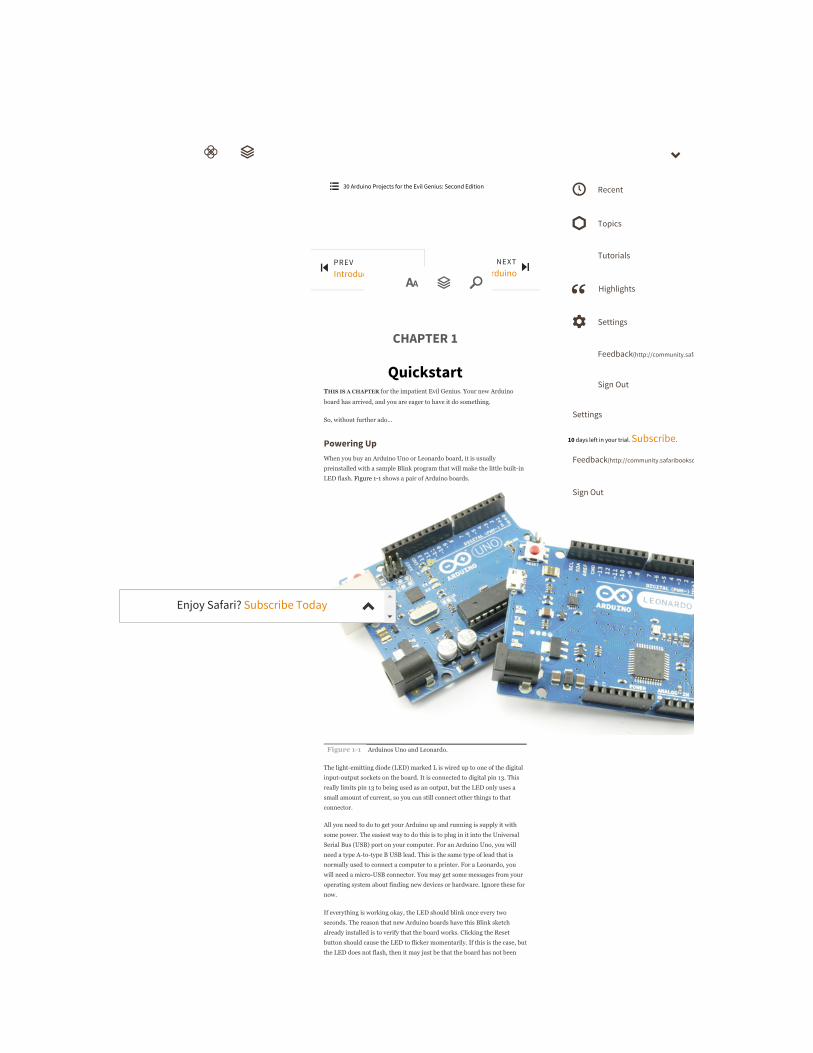
Powering UpWhen you buy an Arduino Uno or Leonardo board, it is usually
preinstalled with a sample Blink program that will make the little builtin
LED flash. Figure 11 shows a pair of Arduino boards.
Figure 11 Arduinos Uno and Leonardo.
The lightemitting diode (LED) marked L is wired up to one of the digital
inputoutput sockets on the board. It is connected to digital pin 13. This
really limits pin 13 to being used as an output, but the LED only uses a
small amount of current, so you can still connect other things to that
connector.
All you need to do to get your Arduino up and running is supply it with
some power. The easiest way to do this is to plug in it into the Universal
Serial Bus (USB) port on your computer. For an Arduino Uno, you will
need a type Atotype B USB lead. This is the same type of lead that is
normally used to connect a computer to a printer. For a Leonardo, you
will need a microUSB connector. You may get some messages from your
operating system about finding new devices or hardware. Ignore these for
now.
If everything is working okay, the LED should blink once every two
seconds. The reason that new Arduino boards have this Blink sketch
already installed is to verify that the board works. Clicking the Reset
button should cause the LED to flicker momentarily. If this is the case, but
the LED does not flash, then it may just be that the board has not been
PREVIntroduction
NEXT2 A Tour of Arduino
ὐ
30 Arduino Projects for the Evil Genius: Second Edition Recent
Topics
Tutorials
Highlights
Settings
Feedback(http://community.safaribooksonline.com)
Sign Out
Settings
10 days left in your trial. Subscribe.
Feedback(http://community.safaribooksonline.com/)
Sign Out
Enjoy Safari? Subscribe Today

programmed with the Blink sketch; but do not despair, as once everything
is installed, we are going to modify and install that script anyway as our
first project.
Installing the SoftwareNow that we have our Arduino working, let’s get the software installed so
that we can alter the Blink program and send it down to the board. The
exact procedure depends on what operating system you use on your
computer. But the basic principle is the same for all.
Install the Arduino development environment, which is the program that
you run on your computer that enables you to write sketches and
download them to the Arduino board.
Install the USB driver that allows the computer to talk to the Arduino’s
USB port. It uses this for programming and sending messages.
The Arduino website (www.arduino.cc(http://www.arduino.cc)) contains the
latest version of the software. In this book we have used Arduino 1.0.2.
Installation on Windows
The instructions that follow are for installing on Windows 7. The
approach is much the same for Vista and XP. The only part that can be a
little difficult is installing the drivers.
Follow the download link on the Arduino home page
(www.arduino.cc(http://www.arduino.cc)), and select the download for
Windows. This will start the download of the Zip archive containing the
Arduino software, as shown in Figure 12. You may well be downloading a
more recent version of the software than the version 1.0.2 shown
(misleadingly, the Arduino team have not got around to renaming the Zip
file yet).
Figure 12 Downloading the Arduino software for Windows.
The Arduino software does not distinguish between different versions of
Windows. The download should work for all versions, from Windows XP
onward. The following instructions are for Windows 7.
Select the Save option from the dialog, and save the Zip file onto your
desktop. The folder contained in the Zip file will become your main
Arduino directory, so now unzip it onto your Desktop. You can move it
somewhere else later if you wish.
You can do this in Windows by rightclicking the Zip file to show the
menu in Figure 13 and selecting the Extract All option. This will open the
Extraction Wizard, shown in Figure 14.

Figure 13 The Extract All menu option in Windows.
Figure 14 Extracting the Arduino file in Windows.
Extract the files to your Desktop.
This will create a new directory for this version of Arduino (in this case,
1.0.2) on your Desktop. You can, if you wish, have multiple versions of
Arduino installed at the same time, each in its own folder. Updates of
Arduino are fairly infrequent and historically have always kept pretty
good compatibility with earlier versions of the software. So unless there is
a new feature of the software that you want to use, or you have been
having problems, it is by no means essential to keep up with the latest
version.
Now that we have got the Arduino folder in the right place, we need to
install the USB drivers. If you have not already done so, plug your
Leonardo or Uno into your computer. Depending on your version of
Windows, there may be some halfhearted attempt by the operating system
to install drivers. Just cancel this at the earliest opportunity; it is unlikely
to work. Instead, you need to open the Device Manager. This is accessed
in different ways depending on your version of Windows. In Windows 7,
you first have to open the Control Panel, then select the option to view
Icons, and you should find the Device Manager in the list.
Under the section “Other Devices,” you should see an icon for “Unknown
Device” with a little yellow warning triangle next to it. This is your
Arduino (Figure 15).
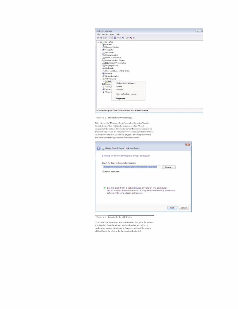
Figure 15 The Windows Device Manager.
Rightclick on the “Unknown Device” and select the option “Update
Driver Software.” You will then be prompted to either “Search
automatically for updated driver software” or “Browse my computer for
driver software.” Select the option to browse and navigate to the “arduino
1.0.2windows\arduino1.0.2\drivers” (Figure 16). Change the version
numbers if you are using a different version of Arduino.
Figure 16 Browsing for the USB drivers.
Click “Next,” and you may get a security warning; if so, allow the software
to be installed. Once the software has been installed, you will get a
confirmation message like the one in Figure 17. Although the message
will be different for a Leonardo, the procedure is identical.

Figure 17 The USB driver Installed successfully.
The Device Manager should now list the right name for the Arduino
(Figure 18).
Figure 18 The Device Manager showing the Arduino.
This is a oneoff process; from now on, whenever you plug in your
Arduino board, its USB drivers will automatically be loaded, and the
Arduino will be ready for action.
Installation on Mac OS X
The process for installing the Arduino software on the Mac is a lot easier
than on the PC.
As before, the first step is to download the file. In the case of the Mac, it is
a Zip file. Once downloaded, doubleclick on the Zip file, which will
extract a single file called “Arduino.app.” This is the whole Arduino
application; just drag it into your Applications folder.
You can now find and launch the Arduino software in your Applications
folder. As you are going to use it frequently, you may wish to rightclick its
icon in the dock and set it to “Keep in Dock.”
Installation on LINUX
There are many different LINUX distributions, and the instructions for
each distribution are a little different. The Arduino community has done a
great job of putting together sets of instructions for each distribution. So
follow the link below and select one of the ten (at the time of writing)

distributions on offer.
Configuring Your Arduino EnvironmentWhatever type of computer you use, you should now have the Arduino
software installed on it. You now need to make a few settings. You need to
specify the serial port that is connected to the Arduino board, and we need
to specify the type of Arduino board that we are using. But first, you need
to connect your Arduino to your computer using the USB lead or you will
not be able to select the serial port.
Next, start the Arduino software. In Windows, this means opening the
“Arduino” folder and clicking on the “Arduino” icon (selected in Figure 1
9). You may prefer to make a shortcut for the Desktop.
Figure 19 Starting Arduino in Windows.
The serial port is set from the Tools menu, as shown in Figure 110 for the
Mac and in Figure 111 for Windows 7—the list of ports for LINUX is
similar to the Mac.
Figure 110 Setting the serial port on the Mac.

Figure 111 Setting the serial port on Windows.
If you use many USB or Bluetooth devices with your Mac, you are likely to
have quite a few options in this list. Select the item in the list that begins
with “dev/tty.usbserial.”
On Windows, the serial port can just be set to COM3 or COM4, whichever
shows up.
From the Tools menu, we can now select the board that we are going to
use, as shown in Figure 112.
Figure 112 Setting the board.
Downloading the Project SoftwareThe sketches (as programs are called in the Arduino world) used in the
book are available as a single Zip file download. The whole download is
less than a megabyte, so it makes sense to download the software for all of

the projects, even if you only intend to use a few. To download them,
browse to www.arduinoevilgenius.com(http://www.arduinoevilgenius.com) and
follow the download links for the second edition of this book.
Whatever your platform, the Arduino software expects to find all your
sketches in your “Documents” folder, contained within a folder called
“Arduino,” which the Arduino software will create the first time it is run.
So place the contents of the Zip file into that folder.
Note that each sketch comes in its own folders, and the sketches are
numbered by project.
Project 1Flashing LEDHaving assumed that we have successfully installed the software, we can
now start on our first exciting project. Actually, it’s not that exciting, but
we need to start somewhere, and this will ensure that we have everything
set up correctly to use our Arduino board.
We are going to modify the example Blink sketch that comes with
Arduino. We will increase the frequency of the blinking and then install
the modified sketch on our Arduino board. Rather than blink slowly, our
board will flash its LED quickly. We will then take the project a stage
further by using a bigger external LED and resistor rather than the tiny
builtin LED.
COMPONENTS AND EQUIPMENT
Software
First, we need to load the Blink sketch into the Arduino software. The
Blink sketch is included as an example when you install the Arduino
environment. So we can load it using the File menu, as shown in Figure 1
13.

Figure 113 Loading the example Blink sketch.
The sketch will open in a separate window (Figure 114); you can, if you
like, now close the empty window that opened when Arduino started.
Figure 114 The Blink sketch.
The majority of the text in this sketch is in the form of comments.
Comments are not actually part of the program but explain what is going
on in the program to anyone reading the sketch.
Comments can be singleline comments that start after a // and continue
to the end of the line, or they can be multiline comments that start with a
/* and end some lines later with a */.
If all the comments in a sketch were to be removed, it would still work in
exactly the same way, but we use comments because they are useful to
anyone reading the sketch trying to work out what it does.
Before we start, a little word about vocabulary is required. The Arduino
community uses the word “sketch” in place of “program,” so from now on
I will refer to our Arduino programs as sketches. Occasionally I may refer
to “code.” Code is programmer speak for a section of a program or even a
generic term for what is written when creating a program. So someone
might say, “I wrote a program to do that,” or they could say, “I wrote some
code to do that.”
To modify the rate at which the LED will blink, we need to change the
value of the delay so in the two places in the sketch where we have
change the value in the parentheses to 200 so that it appears as
This is changing the delay between turning the LED on and off from 1000
milliseconds (1 second) to 200 milliseconds (1/5th of a second). In
Chapter 3 we will explore this sketch further, but for now, we will just
change the delay and download the sketch to the Arduino board.
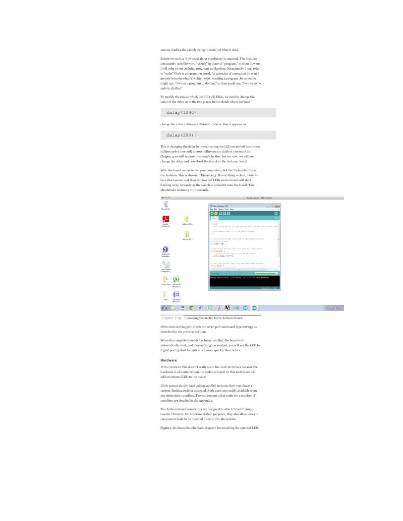
With the board connected to your computer, click the Upload button on
the Arduino. This is shown in Figure 115. If everything is okay, there will
be a short pause, and then the two red LEDs on the board will start
flashing away furiously as the sketch is uploaded onto the board. This
should take around 5 to 10 seconds.
Figure 115 Uploading the sketch to the Arduino board.
If this does not happen, check the serial port and board type settings as
described in the previous sections.
When the completed sketch has been installed, the board will
automatically reset, and if everything has worked, you will see the LED for
digital port 13 start to flash much more quickly than before.
Hardware
At the moment, this doesn’t really seem like real electronics because the
hardware is all contained on the Arduino board. In this section we will
add an external LED to the board.
LEDs cannot simply have voltage applied to them; they must have a
currentlimiting resistor attached. Both parts are readily available from
any electronics suppliers. The component order codes for a number of
suppliers are detailed in the Appendix.
The Arduino board connectors are designed to attach “shield” plugin
boards. However, for experimentation purposes, they also allow wires or
component leads to be inserted directly into the sockets.
Figure 116 shows the schematic diagram for attaching the external LED.

Figure 116 Schematic diagram for an LED connected to the
Arduino board.
This kind of schematic diagram uses special symbols to represent the
electronic components. The LED appears rather like an arrow, which
indicates that lightemitting diodes, in common with all diodes, only allow
the current to flow in one direction. The little arrows next to the LED
symbol indicate that it emits light.
The resistor is just depicted as a rectangle. Resistors are also often shown
as a zigzag line. The rest of the lines on the diagram represent electrical
connections between the components. These connections may be lengths
of wire or tracks on a circuit board. In this case, they will just be the wires
of the components.
We can connect the components directly to the Arduino sockets between
the digital pin 12 and the GND pin, but first we need to connect one lead
of the LED to one lead of the resistor.
It does not matter which lead of the resistor is connected to the LED;
however, the LED must be connected the correct way. The LED will have
one lead slightly longer than the other, and it is the longer lead that must
be connected to digital pin 12 and the shorter lead that should be
connected to the resistor. LEDs and some other components have the
convention of making the positive lead longer than the negative one.
To connect the resistor to the short lead of the LED, gently spread the
leads apart, and twist the short lead around one of the resistor leads, as
shown in Figure 117.
Figure 117 An LED connected to a serial resistor.
Then push the LED’s long lead into the digital pin 12 and the free lead of
the resistor into one of the two GND sockets. This is shown in Figure 118.
Sometimes it helps to bend a slight kink into the end of the lead so that it
fits more tightly into the socket.

Figure 118 An LED connected to the Arduino board.
We can now modify our sketch to use the external LED that we have just
connected. All we need to do is change the sketch so that it uses digital pin
12 instead of 13 for the LED. To do this, we change the line
to read
Now upload the sketch by clicking the Upload to IO Board button in the
same way as you did when modifying the flash rate.
BreadboardTwisting together a few wires is not practical for anything much more
than a single LED. A breadboard allows us to build complicated circuits
without the need for soldering. In fact, it is a good idea to build all circuits
on a breadboard first to get the design right and then commit the design
to solder once everything is working.
A breadboard comprises a plastic block with holes in it, with sprung metal
connections behind. Electronic components are pushed through the holes
at the front.
Underneath the breadboard holes, there are strips of connectors, so all the
holes in a strip are connected together. The strips have a gap between
them so that integrated circuits in dualinline packaging can be inserted
without leads on the same row being shorted together.
We can build this project on a breadboard rather than with twisted wires.
Figure 119 shows a photograph of this. Figure 120 makes it a little easier
to see how the components are positioned and connected together.
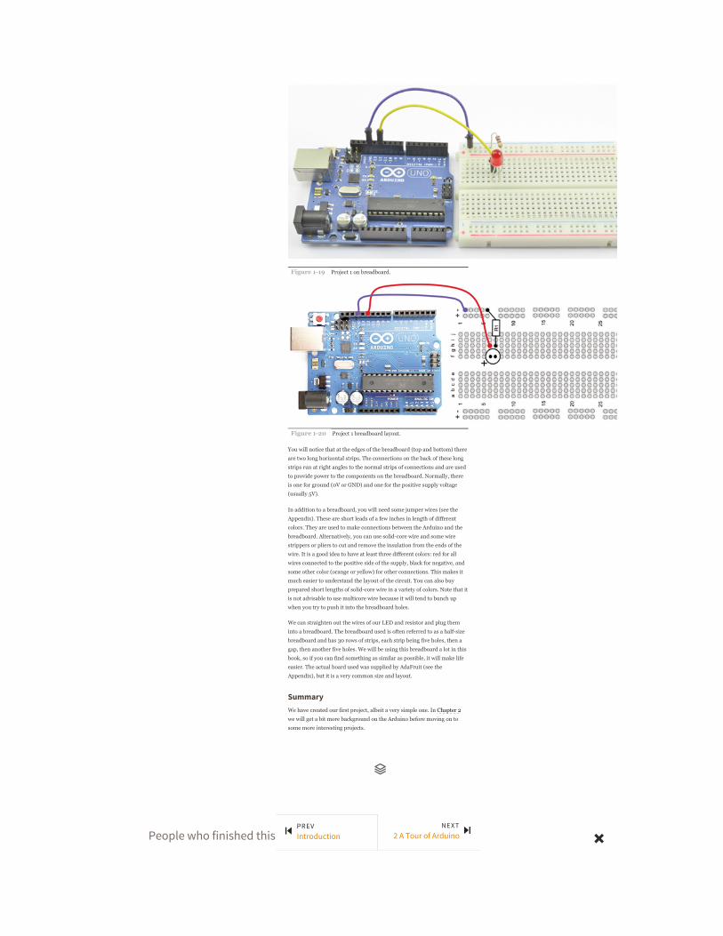
Figure 119 Project 1 on breadboard.
Figure 120 Project 1 breadboard layout.
You will notice that at the edges of the breadboard (top and bottom) there
are two long horizontal strips. The connections on the back of these long
strips run at right angles to the normal strips of connections and are used
to provide power to the components on the breadboard. Normally, there
is one for ground (0V or GND) and one for the positive supply voltage
(usually 5V).
In addition to a breadboard, you will need some jumper wires (see the
Appendix). These are short leads of a few inches in length of different
colors. They are used to make connections between the Arduino and the
breadboard. Alternatively, you can use solidcore wire and some wire
strippers or pliers to cut and remove the insulation from the ends of the
wire. It is a good idea to have at least three different colors: red for all
wires connected to the positive side of the supply, black for negative, and
some other color (orange or yellow) for other connections. This makes it
much easier to understand the layout of the circuit. You can also buy
prepared short lengths of solidcore wire in a variety of colors. Note that it
is not advisable to use multicore wire because it will tend to bunch up
when you try to push it into the breadboard holes.
We can straighten out the wires of our LED and resistor and plug them
into a breadboard. The breadboard used is often referred to as a halfsize
breadboard and has 30 rows of strips, each strip being five holes, then a
gap, then another five holes. We will be using this breadboard a lot in this
book, so if you can find something as similar as possible, it will make life
easier. The actual board used was supplied by AdaFruit (see the
Appendix), but it is a very common size and layout.
SummaryWe have created our first project, albeit a very simple one. In Chapter 2
we will get a bit more background on the Arduino before moving on to
some more interesting projects.
People who finished this also enjoyed:
PREVIntroduction
NEXT2 A Tour of Arduino

Recommended / Queue / Recent / Topics / Tutorials / Settings / Blog(http://blog.safaribooksonline.com) /Feedback(http://community.safaribooksonline.com/) / Sign Out© 2015 Safari(http://www.safaribooksonline.com/). Terms of Service / Privacy Policy
ZMapperfrom: ESSENTIAL ZBRUSH by Wayne RobsonReleased: June 200939 MINS
Digital Media
BOOK SECTIONὍ
Design and Compositionfrom: Painter X Creativity by Jeremy SuttonReleased: September 201223 MINS
Digital Media
BOOK SECTIONὍ
Enabling Network Load Balancing(NLB) on your DirectAccess serversfrom: Windows Server 2012 R2 AdministratorCookbook by Jordan KrauseReleased: January 2015
9 MINSMicrosoft / Networking
BOOK SECTIONὍ
Source Data is Never Enoughfrom: TIBCO Spotfire – A Comprehensive Primer byMichael PhillipsReleased: February 20159 MINS
Big Data
BOOK SECTIONὍ
- UTILIZATION DROPS SHARPLY WITHINDIVIDUAL RESPONSIBILITYfrom: Company That Solved Heath Care by JohnTorinusReleased: October 201012 MINS
Business
BOOK SECTIONὍ
Chapter 12: Panamafrom: The International Living Guide to RetiringOverseas on a Budget: How to Live Well on $25,000a Year by Dan Prescher...Released: March 201418 MINS
Personal & Professional Development
BOOK SECTIONὍ
Scripting a media playerfrom: Raspberry Pi Blueprints by Dan NixonReleased: March 20155 MINS
DIY & Hardware
BOOK SECTIONὍ
L: LOVEfrom: The Dream Cafe: Lessons in the Art of RadicalInnovation by Dr Geoff Crook...Released: April 201517 MINS
Business / Personal & Professional Development
BOOK SECTIONὍ
Chapter 1. What Is a CertifiedTechnology Specialist?from: CTS Certified Technology Specialist ExamGuide, Second Edition by Brad GrimesReleased: May 201312 MINS
Certification
BOOK SECTIONὍ
Using an ADC to Interface any AnalogSensor with the Raspberry Pifrom: Raspberry Pi Sensors by Rushi GajjarReleased: April 20159 MINS
DIY & Hardware
BOOK SECTIONὍ