1 pavement lifting & soil stabilization control soil stabilization, lifting of pavement...
TRANSCRIPT
1
Pavement Lifting & Soil Stabilization Control
SOIL STABILIZATION,
LIFTING OF PAVEMENT STRUCTURES
AND UNDERGROUND INFRASTRUCTURE REPAIRS
USING
DEEP INJECTION (DI)
HIGH DENSITY POLYURETHANE (HDP)
Joe KindlerURETEK USA of Ohio

2
AGENDA
• WHAT IS HIGH DENSITY POLYURETHANE
• APPLICATIONS
• TESTING AND MEASURING
• CASE STUDIES
• QUESTIONS

3
WHAT IS HIGH DENSITY POLYURETHANE
• Composition• Resin & Hardener• 1:1 mixing ratio by volume• Exothermic chemical reaction generates CO2
• CO2 gas causes expansion of material and creates up to 8000 psf lifting pressure
• Fast reaction – complete in < 1 minute
• No shrinkage during curing
4
WHAT IS HIGH DENSITY POLYURETHANE
• Characteristics• Lightweight – 3 to 10 pcf• As material cools Rigid Structural Polymer
• Spread is limited due to speed of reaction
• High Compressive & Tensile Strength
• Compressive Strength and Tensile Strength are directly proportional to Density
• Chemical resistance / Ultraviolet radiation
5
WHAT IS HIGH DENSITY POLYURETHANE
• Quality HDP Material Characteristics • Hydro-insensitive in that it contains water insoluble diluents - can be injected into wet soils and even standing or flowing water
• NSF 61 Certified - can be used with potable water systems
• Environmentally Inert - material has no impact

6
APPLICATIONS
• Settled Pavements• Roadways• Dams• Runways, Taxiways, Aprons• Bridge Approaches & Departures• Asphalt, Concrete or Composite• Dips or Faulted Joints
• Underground Infrastructures - Leaking / Settled
• Settlement in Buildings
7
APPLICATIONS
• Pavement or Structure Settlement Due to:• Voids• Poor Soil Conditions in Sub-base• Undersized Pavement Structure for Current Mission
• Leaking Underground Drainage System Causing Loss of Soil Support

8
URETEK DEEP INJECTION UDI
9
DEEP INJECTION PROCESS
• Compaction Displacement Grouting Process
• Densification of soils is achieved by the controlled expansive force of the polymers
• Adequate densification confirmed by movement of bearing load and field testing (e.g., DCP and FWD)

10
DEEP INJECTION PROCESS
• Drill 5/8” holes in pavement• Hole pattern is 3’ to 4’ on center• Insert injection tubes to proper depth
• Holes can be drilled up to 2” to accommodate multiple tubes for multiple injection depths
• Typical injection depths within -10’
• Can inject down to 40’

11
DEEP INJECTION PROCESS
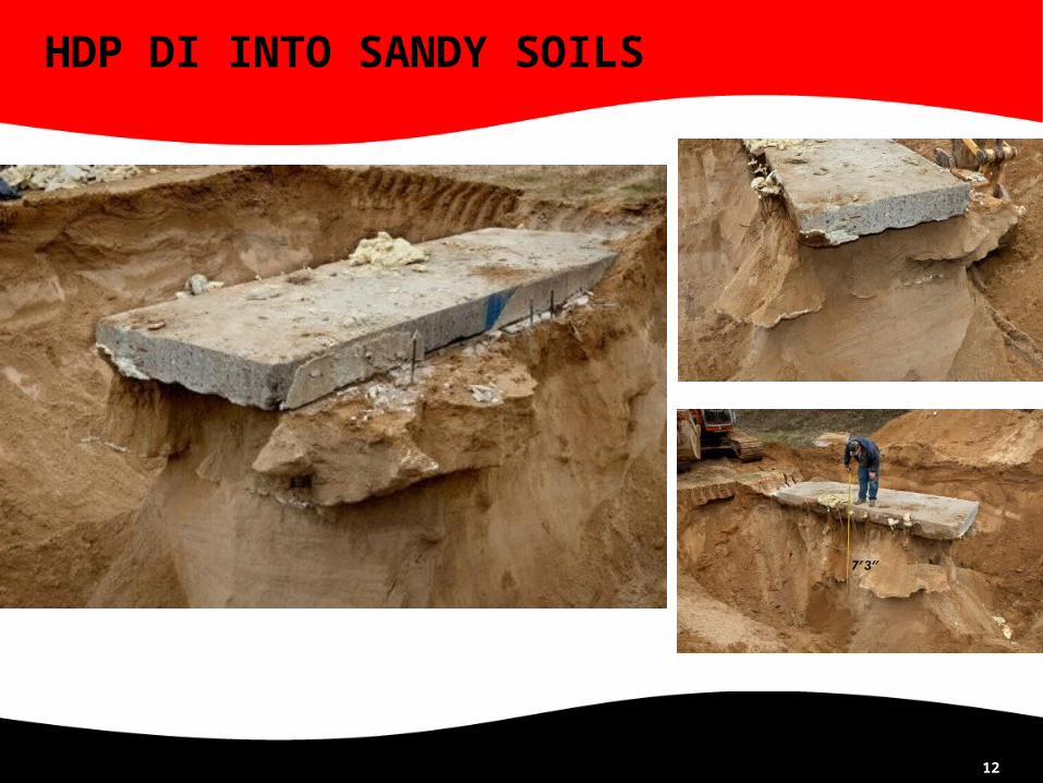
• Can inject full range of soils:• Injection into sandy soils creates sandstone
• Stiff clays – inject above and/or below layer
• Highly organics – material consumption will be high – currently studying techniques to minimize consumption by creating honeycomb “confinement cells” structural support
12
HDP DI INTO SANDY SOILS

1313
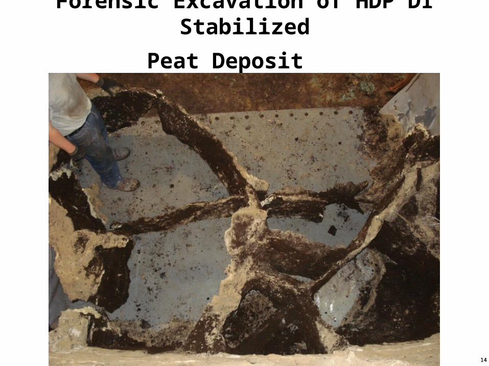
Forensic Excavation of HDP DI Stabilized
Peat Deposit
1414
Forensic Excavation of HDP DI Stabilized
Peat Deposit

Sample taken from minus 12 feet. 2’ x 1 ½’ x 1’ and weighed over 80 pounds.

The Polymer is very dense.

Precast Concrete Panels for Rapid Repair of Airfield Rigid pavements
REZA ASHTIANI, PHD
ATHAR SAEED, PHD, PE
Applied Research Associates, Inc.
MICHAEL HAMMONS, PHD, PE
Air Force Research Laboratory

18
Summary
Three pre-cast PCC slab installation techniques were investigated in this research effort
High Density Polyurethane (HDP) foam was used for leveling and installation of Slab#1 and Slab#2. Flowable fill was used for Slab#3
Performance of the repaired sections were assessed through analysis of:
• Load Transfer Efficiency Based on Deflections (LTE)
• Load Transfer Efficiency Based on Stresses (LTE)
• Load Transfer Based on FAA Design Criteria (LT)
• Analysis of Joint Stiffness based on MEPDG criteria [log (Jc)+R]
• Analysis based on Dissipated Deformation Energy to Subgrade
• Analysis of Responses of Pre-Cast Panels using FE
19
2011 TRB PRESENTATION BY AFRL
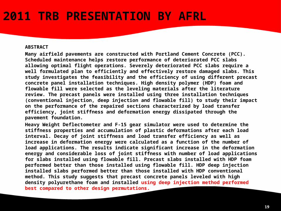
ABSTRACT
Many airfield pavements are constructed with Portland Cement Concrete (PCC). Scheduled maintenance helps restore performance of deteriorated PCC slabs allowing optimal flight operations. Severely deteriorated PCC slabs require a well formulated plan to efficiently and effectively restore damaged slabs. This study investigates the feasibility and the efficiency of using different precast concrete panel installation techniques. High density polymer (HDP) foam and flowable fill were selected as the leveling materials after the literature review. The precast panels were installed using three installation techniques (conventional injection, deep injection and flowable fill) to study their impact on the performance of the repaired sections characterized by load transfer efficiency, joint stiffness and deformation energy dissipated through the pavement foundation.
Heavy Weight Deflectometer and F-15 gear simulator were used to determine the stiffness properties and accumulation of plastic deformations after each load interval. Decay of joint stiffness and load transfer efficiency as well as increase in deformation energy were calculated as a function of the number of load applications. The results indicate significant increase in the deformation energy and considerable loss of joint stiffness with number of load applications for slabs installed using flowable fill. Precast slabs installed with HDP foam performed better than those installed using flowable fill. HDP deep injection installed slabs performed better than those installed with HDP conventional method. This study suggests that precast concrete panels leveled with high density polyurethane foam and installed using deep injection method performed best compared to other design permutations.

20
DOD TRANSPORTATION PROJECTS
• Andrews AFB MD – Soil Stabilization and Pavement Lifting under Air Force One Runway (repair in place August 1999 until December 2010)
• Tyndall AFB FL – Soil Stabilization and Void Filling under the Drone Recovery Dock (repair in place February 2004 until present)
• MacDill AFB FL – Void Filling under an Apron (repair in place April 2004 until present)

21
DOD TRANSPORTATION PROJECTS
• NAS Corpus Christi – Soil Stabilization under a Runway (2010)
• Lackland AFB TX – Joint Alignment and Soil Stabilization under an Apron (2011)
• NFESC – Develop an Airfield Damage Repair (ADR) system for US Navy Reference: TR-NAVFAC ESC-EX-1201, Cody M. Reese, Jan 2012
• AFRL – Alignment and Stabilization of Pre-cast Slabs for USAF repair system Reference: TSW 2012 Paper # 89 (Ashtiani, Saeed, & Hammons) to be presented Thu 8 Mar 12, 1015, in the San Antonio Room

22
NAVFAC ADR PROJECT - CONCEPT
Perform expedient repair of craters on airfields by
injecting polyurethane into loose backfill (underlying a rapid set concrete cap)
to achieve soil stabilization
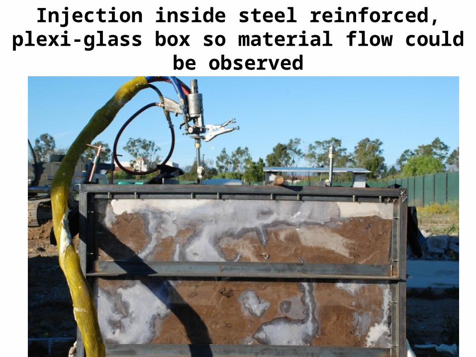
EXPEDIENT REPAIR OF ANDREWS AFBRUNWAY 01L/19R
Injection inside steel reinforced, plexi-glass box so material flow could
be observed

EXPEDIENT REPAIR OF ANDREWS AFBRUNWAY 01L/19R
Stabilized soil mass was free-standingafter box removed

EXPEDIENT REPAIR OF ANDREWS AFBRUNWAY 01L/19R
Vertical load applied using an excavator

EXPEDIENT REPAIR OF ANDREWS AFBRUNWAY 01L/19R
Soil mass would not crush, but excavator was lifted 11 inches
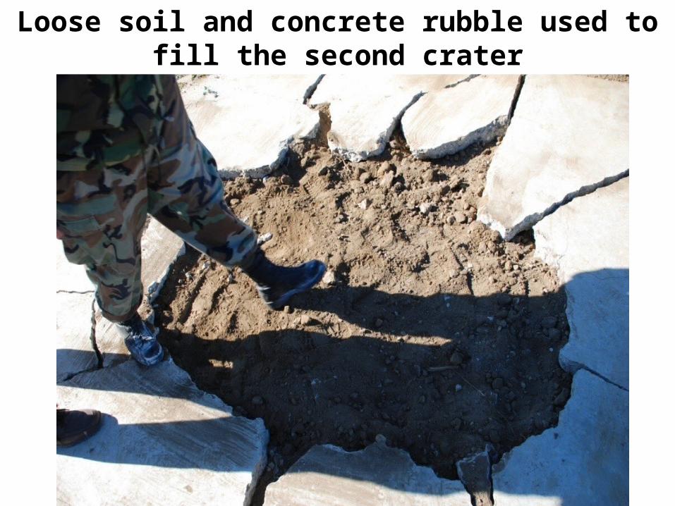
EXPEDIENT REPAIR OF ANDREWS AFBRUNWAY 01L/19R
Loose soil and concrete rubble used tofill the second crater

EXPEDIENT REPAIR OF ANDREWS AFBRUNWAY 01L/19R
Excavation revealed polyurethane compacted the backfill material and
filled the voids
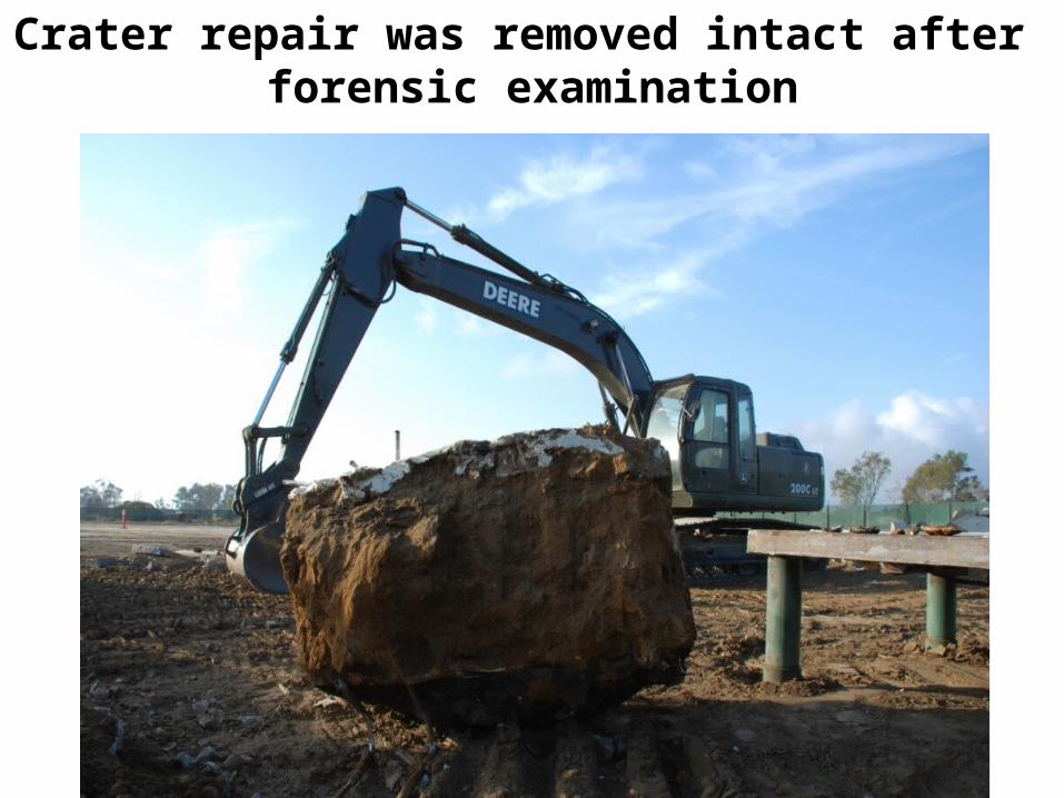
EXPEDIENT REPAIR OF ANDREWS AFBRUNWAY 01L/19R
Crater repair was removed intact after forensic examination

30
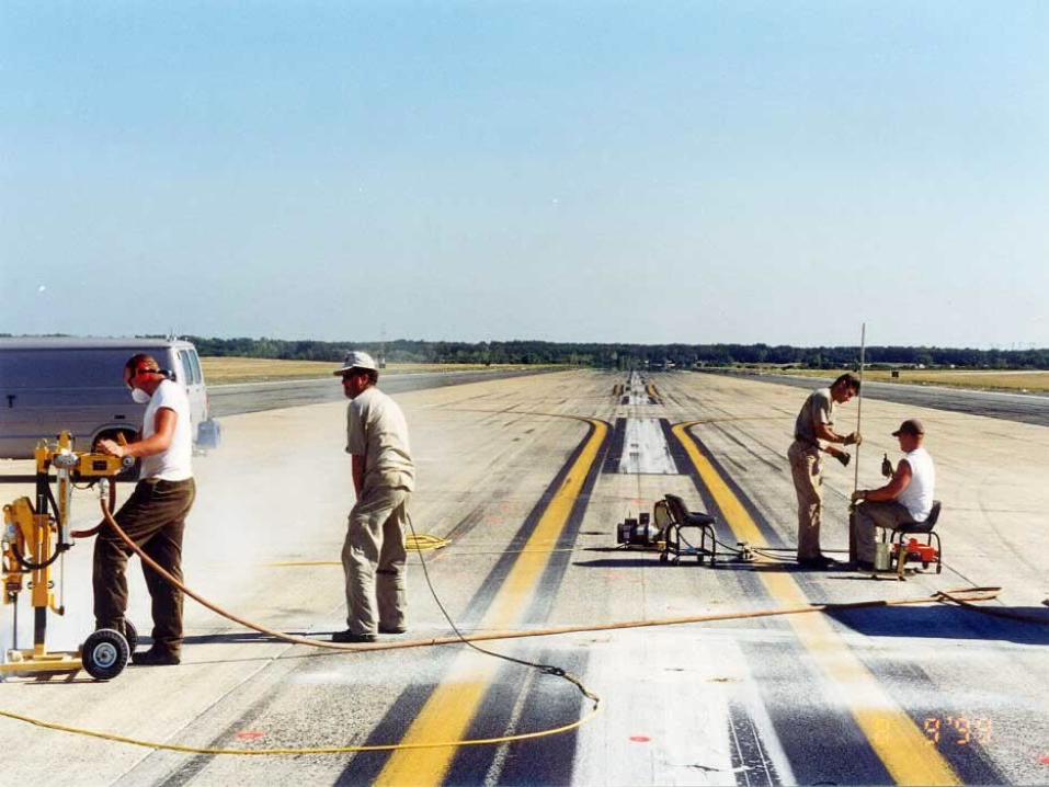
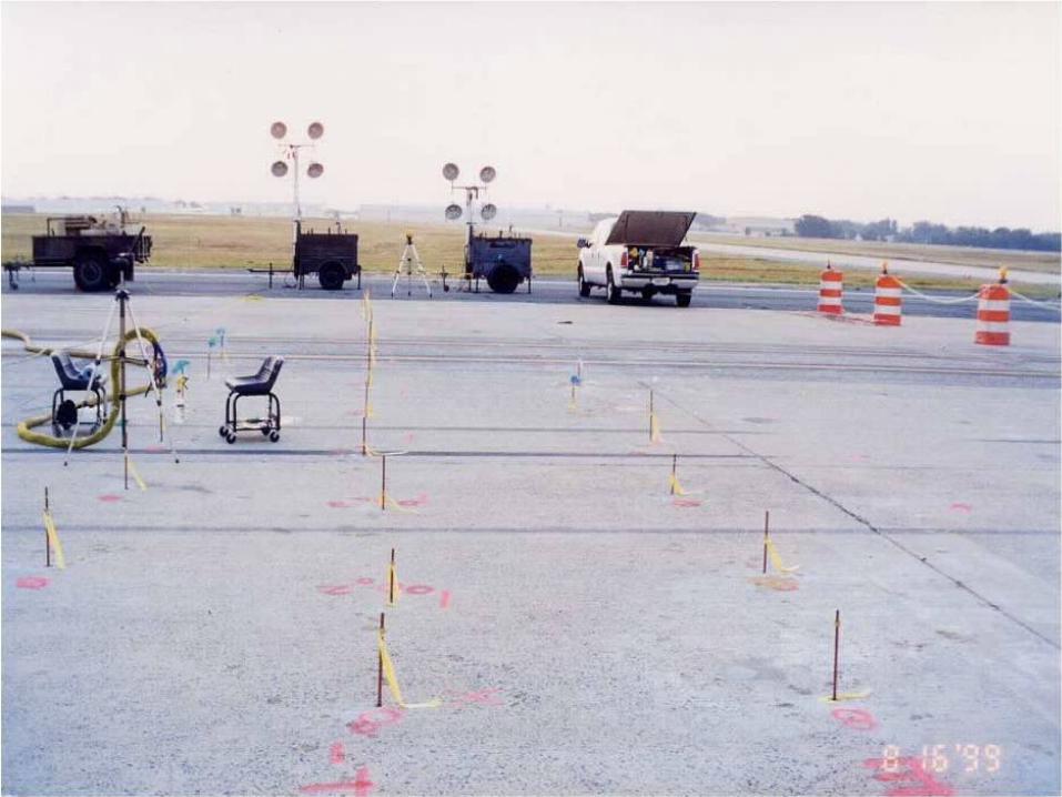
ANDREWS AIR FORCE BASE
JOB LOCATION: 89 CES/CECE 3710 FETCHET AVE.ANDREWS AFB, MD 20762Runway 01L / 19R
35
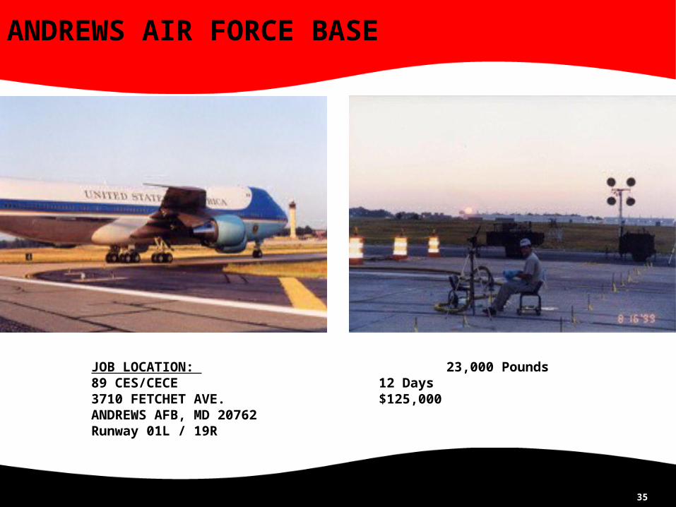
ANDREWS AIR FORCE BASE
JOB LOCATION: 23,000 Pounds89 CES/CECE 12 Days3710 FETCHET AVE. $125,000ANDREWS AFB, MD 20762Runway 01L / 19R

•ODOT8 1-71SB MM58
•42” Bored Gas Line 9’ Below
•7.5” Asphalt, 9” Concrete & 6” Base
•DCP 8’ Weak Soils
•10hrs 9-2pm 2 days

DCP TESTING
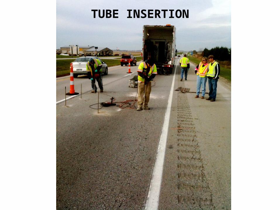
TUBE INSERTION
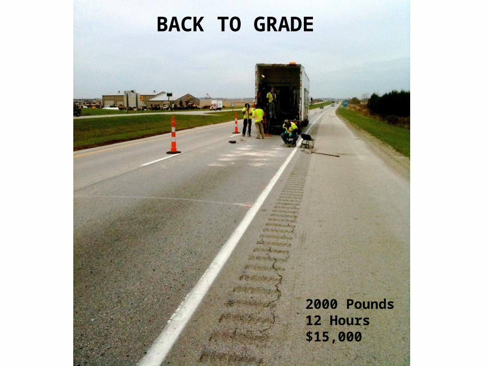
BACK TO GRADE
2000 Pounds12 Hours$15,000
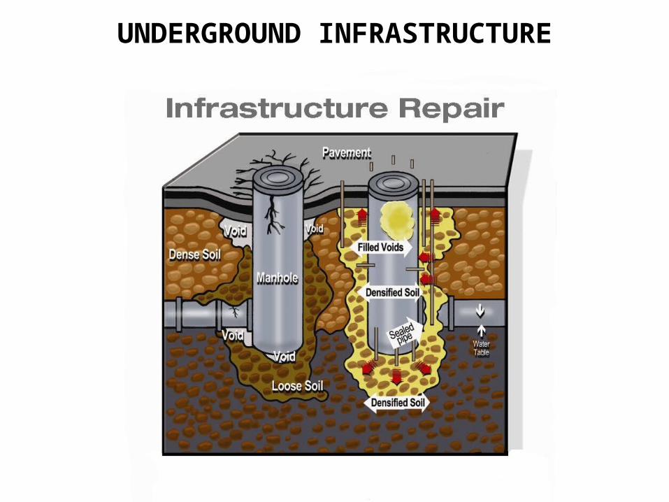
UNDERGROUND INFRASTRUCTURE


45
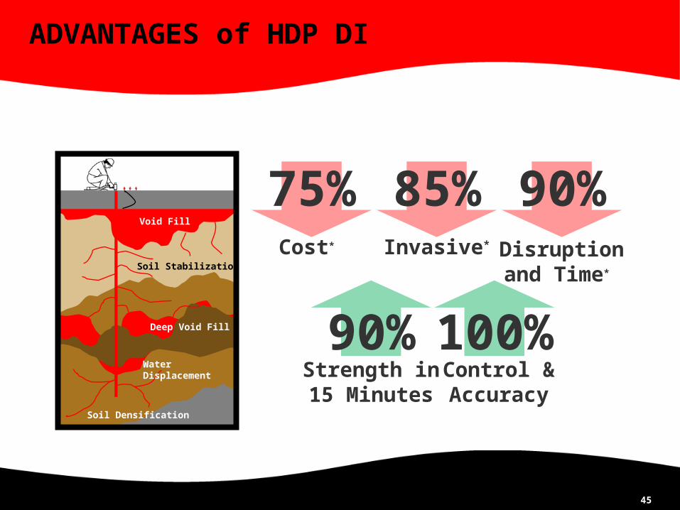
ADVANTAGES of HDP DI
Cost*
75% 85%Invasive*
90%Disruptionand Time*
100%90%Strength in15 Minutes
Control &Accuracy
Soil Densification
Soil Stabilization
Deep Void Fill
WaterDisplacement
Void Fill
46
ANY QUESTIONS?
Available on State Contract and GSA Schedule
Thank You
Joe KindlerURETEK of Ohio
866-849-6017