1 parallel sensing/probing architecture and adaptive...
TRANSCRIPT
1
Parallel Sensing/Probing Architecture and AdaptiveProtocol Design for Opportunistic Networks
Mohammad J. Abdel-Rahman, Harish Kumar Shankar, and Marwan Krunz
Technical ReportTR-UA-ECE-2015-1
Abstract—The proliferation of bandwidth-hungry multimediatraffic over IEEE 802.11-based WLANs has overcrowded theISM bands. The opening of the UHF TV band by the FCCfor unlicensed opportunistic operation promises to relieve thedemand on ISM bands. However, supporting bandwidth-intensiveapplications over TV white spaces can be quite challenging, dueto the unpredictable nature of spectrum availability combinedwith the fluctuations of channel quality. The realization ofthis herculean feat through unlicensed usage, whilst providingprotection to licensed primary users, requires intelligent andadaptive protocol design. In this paper, we propose a QoS-aware parallel sensing/probing architecture, called QASPA, whichexploits inherent channel and user diversities exhibited by thewireless system. Aiming at maximizing the sensing efficiencywhile achieving a high detection accuracy, QASPA incorporatesan optimal adaptive double-threshold-based sensing mechanism.It also embodies a cross-layer protocol, which uses an adaptiveframing structure to minimize the control overhead, and a novelspectrum assignment strategy targeted at improving the spatialreuse of the network. The proposed spectrum assignment strategysupports both channel bonding and aggregation. Our simulationsvalidate the ability of QASPA in guaranteeing the demandsof high-bandwidth opportunistic flows while supporting low-bandwidth flows. They also show the superior performance ofQASPA compared to the scheme used in the ECMA-392 standardfor opportunistic indoor streaming.
Keywords—Channel allocation, channel probing, integer pro-gramming, multimedia communication, opportunistic access radio,optimal stopping theory, spectrum sensing.
I. INTRODUCTION
W IRELESS communications have witnessed tremendousgrowth over the last decade, placing significant demand
for RF spectrum. Spectrum scarcity is only expected to worsenin time, as new wireless services make their way to the com-mercial world. The FCC has accordingly declared a “spectrumcrisis.” In the words of its Chairman Julius Genachowski, “thebiggest threat to the future of mobile communications . . . isthe looming spectrum crisis” [1].
Traditionally, much of the spectrum is statically licensedfor a given use in a given geographic area. Exceptions to thisnorm include the ISM bands, which facilitate many indoor andshort-range communications (e.g., WLANs, Bluetooth, etc.).However, these bands are reaching their capacity limit, as morebandwidth-hungry multimedia traffic is being pushed throughthem (e.g., media steaming, interactive gaming, real-timevoice/video calling, etc.). Dynamic spectrum access (DSA)
tries to address the spectrum crisis by allowing spectrum-agiledevices with cognitive radio (CR) capabilities to operate op-portunistically as secondary users (SUs) over certain licensedbands, including the TV white spaces (TVWS). However,supporting the quality of service (QoS) requirements of high-bandwidth applications using the DSA paradigm is a herculeanfeat, to say the least. These applications require sustainedthroughput (in bps) to maintain acceptable video quality. Thiscan be quite difficult to guarantee in a DSA environmentthat is characterized by spatiotemporal variations in spectrumavailability. In fact, the mere presence of spectrum holesthat, on average, exhibit low primary user (PU) activity isnot enough to enable bandwidth-intensive communications.One also needs to take into account the quality of theseholes. To minimize the disruption to the high-bandwidth flows,the spectrum sensing process needs to identify stable idlechannels, i.e., ones that are expected to remain idle for anextended period of time.
The main objective of this paper is to provide a frameworkfor opportunistically transporting heterogeneous traffic, whichincludes high-bandwidth flows as well as best-effort flows,over TVWS without interfering with the operation of PUs.To this end, we design a QoS-aware parallel sensing/probingarchitecture called QASPA and a cross-layer protocol thatencompasses all the needed components. QASPA involves fivekey novelties. First, it uses estimated PU activity profiles toconstruct a schedule for parallel (concurrent) sensing/probingof different channels, and for determining the best channel touse for control and management over the next frame. In con-trast to [2], in which channel quality is inferred by periodicallyprobing random spectral bands without any scheduling, in ourscheme links are scheduled for sensing/probing such that therate demands of prospective traffic flows are probabilisticallyguaranteed to be satisfied.
Second, QASPA adopts an adaptive TDMA-based framestructure whose objective is to minimize the control over-head and hence maximize the data-transmission period. Thisscheme is intended to address the deficiencies in fixed-frameprotocols, including OP-MAC [3] and the one used in theECMA-392 standard for opportunistic media streaming [4].ECMA-392 follows a master-slave approach for managingportable/personal devices operating over TVWS. It uses ahybrid of ad hoc and infrastructure-based network architectures(see Fig. 1). Specifically, a master device acts as a centralizedentity, and is responsible for coordinating associated slave

2
Fig. 1: Network topology used in our design.
devices by exchanging control messages with them. However,on the data plane, communications among the slave devicescan take place directly or via the master device.
Third, QASPA uses a novel multi-channel sensing/probingscheme that exploits the inherent multi-user diversity of awireless system to maximize the number of discovered oppor-tunities over a given time period. Several schemes have beendeveloped in the literature to maximize the spectrum utilizationwhile limiting interference onto PUs (see, for example, [5]).These schemes do not exploit multi-user diversity, wherebythe quality of a particular channel varies from one linkto another. Many protocols have been proposed to improvethe spatial reuse of a network (e.g., [6]–[8]). However, ourproblem is further complicated by the need to maximize thenetwork’s spatial reuse while guaranteeing the rate demandsof high priority (HP) flows and ensuring interference-free PUcommunications.
Fourth, we integrate into QASPA an optimal adaptivedouble-threshold-based spectrum sensing algorithm, whichaims at maximizing the spectrum sensing efficiency whileachieving a high PU detection accuracy. In contrast tothe conventional single-threshold sensing approach, double-threshold sensing schemes can simultaneously achieve lowmiss-detection and low false-alarm probabilities within a shortsensing time [9]. However, double-threshold sensing involvesan “uncertainty region:” If the sensing outcome falls betweenthe two sensing thresholds (i.e., in the uncertainty region),the channel is considered neither busy nor idle [9]. In ourwork, we address this problem by adaptively adjusting thechannel sensing time, so that the uncertainty region is reducedwhile, at the same time, the required miss-detection andfalse-alarm probabilities are met. In contrast to [10], in ourprotocol the total sensing time per frame is fixed, and theobjective of our adaptive scheme is to maximize the numberof discovered opportunities within the allocated sensing time,while maintaining a required detection accuracy. We formulatethe optimal adaptive double-threshold-based sensing problemusing optimal stopping theory [11]. Optimal stopping theoryhas been previously used in single-threshold-based systemsto optimize the number of sensed channels [12]. In thispaper, we use this theory to optimize the channel sensing
time, assuming a double-threshold-based system. Unlike thecooperative sensing scheme in [13], our scheme is efficienteven with a small number of operational SUs in the network.As a result, we do not compromise the sensing accuracy evenwhen the number of operational SUs is small.
Finally, using the outcome of the channel sensing/probingprocess, we design a centralized spectrum assignment schemefor QASPA that supports channel bonding and aggregation,and that aims at maximizing the number of concurrentlyactive flows. Rather than focusing on the performance of anindividual link, we are interested in optimizing the overallefficiency of the entire opportunistic network.
The rest of the paper is organized as follows. In Section II,we define our network model. We provide an overview ofQASPA in Section III. The adaptive frame structure is intro-duced in Section IV, followed by the proposed parallel sens-ing/probing design in Section V. In Section VI, we present thechannel allocation scheme. We evaluate the proposed designin Section VII. Main conclusions are provided in Section VIII.
II. NETWORK MODEL AND PROTOCOL ASSUMPTIONS
We consider an opportunistic CR network (CRN) with acentralized controller, called the master device (MD) (seeFig. 1), which plays an analogous role to a wireless accesspoint (AP). In contrast to a WiFi-based AP, data communi-cations (i.e., user payload) in our setup can occur directlybetween any two nodes (two slave devices, or a slave deviceand the MD), whereas control information (e.g., schedulinginformation, channel quality reporting, etc.) can be exchangedonly between a slave device and the MD. The conventionalviewpoint of SU-PU coexistence is preserved, wherein SUsstrive to communicate over channels that are not used by PUs.An arbitrary number of peer-to-peer (P2P) links, comprisedof CR-enabled Tx-Rx pairs, become associated with the MDthrough appropriate signaling that occurs before initiating anydata communication. Each device is equipped with a half-duplex transceiver, operating at a constant transmission power.Hence, a node can only listen to or transmit over one channelat a time. This setup is the same as the one used in the ECMA-392 architecture [4].
We classify the traffic over active P2P links into two classes:bandwidth-intensive HP flows and best-effort low priority (LP)flows. Specifically, flows with a rate demand greater than RthMbps are classified as HP, and all other flows are deemedas LP flows. The type of flow (HP/LP) carried by a link isindicated using a single bit in the association packet sent tothe MD. Let L represent the set of HP flows in the network(|L| = L). HP flows are assumed to be long-lived, with astringent rate demand of R(j)
d for flow j ∈ L. We envisionseparate communication paths for control and data. All controlpackets needed to initiate data communications along a givenlink are exchanged between the MD and data sender of thatlink. On the other hand, once the MD allocates channelsfor links, data exchanges take place between the respectivepeer devices without any intervention from the MD. All peerdevices are assumed to be within the communication range ofthe MD, which is typically the case in indoor environments.

3
Let N (|N | = N ) denote the set of orthogonal channels inthe UHF band that can be used opportunistically. We requirethat no two links can transmit over the same channel at thesame time. The channel quality, obtained through probing, isassumed to be stationary during the channel’s coherence time,denoted by τ
(i)c for channel i ∈ N . The channel quality is
also assumed to be link-dependent. PU activity over channeli is modeled as a continuous-time Markov process, whichalternates between busy and idle states, with average busyand idle durations of T
(i)on and T
(i)off , respectively (see, for
example, [14], [15]).
III. PROTOCOL OVERVIEW
To support opportunistic high-bandwidth applications, wedesign a QoS-aware parallel sensing/probing architecture(QASPA) that uses a predefined frame length Tframe. Syn-chronization among various SUs is achieved by disseminatingcontrol packets over a dynamically assigned control channel(CC), which is determined on-the-fly by the MD based onthe estimated PU channel-usage profile. Similar to ECMA-392, in our setup each frame consists of a number of mediumaccess slots (MAS), reserved for various operations, includingnetwork-wide synchronization, parallel sensing/probing, con-current data communication, etc.
QASPA follows an adaptive frame structure (AFS) design,whereby fields used to support various protocol operationsmay vary from one frame to another, even though the overallframe length is still fixed at Tframe. This design is intended toeliminate redundant operations, resulting in drastic reductionin the protocol overhead and improvement in the networkgoodput. A summary of the main functions of the proposedprotocol is provided below.Association. In line with [16], we assume the existence of anintelligent AP discovery mechanism for associating prospec-tive P2P links with the MD and establishing a synchronizednetwork. Once associated, links carrying HP flows providetheir rate demands to the MD. Rate demands play a key rolein the operation of other elements of the protocol.Beacon Period (BP). Beacons are transmitted by the MD intwo instances. First, at the beginning of each frame, the typeof the TDMA frame to be used (as determined by the AFSalgorithm) is broadcasted to all links in the network. Second,towards the end of the frame, the newly designated CC for thefollowing frame period is broadcasted to the entire network.Allowing the CC to be adjusted on a per-frame basis givesgreat flexibility and robustness against fast PU dynamics.Sensing/Probing Scheduling. The scheduling of concurrentsensing/probing processes forms the crux of the QASPAdesign. The MD schedules the channels that various linksneed to sense/probe during the spectrum discovery phase.Such scheduling takes into account the rate demands of HPflows and the estimated PU profiles, and attempts to maximizethe number of discovered spectrum opportunities (hence, thenumber of active links in the network). Unlike the schemesin [2], our sensing/probing scheduling takes into account thelink-dependent channel quality obtained from previous probinginstances. In [2], the quality of one channel over a given link is
used to infer the quality of the other channels, based on simplepath-loss models. This is not accurate for indoor settings,where the effect of the prevailing multi-path conditions overthe other channels.Reporting. After sensing/probing a specified set of channels,each link reports the PU state of these channels along withtheir measured qualities (if detected idle) to the MD. Thisinformation is used by the MD for channel allocation.Channel Assignment. The MD strives to maximize the num-ber of admitted flows with satisfied rate demands (HP and LP),by incorporating channel bonding and aggregation techniques.We introduce a second round of probing to further increasethe admission probability. The major motivation behind thisdesign is to support multiple flows simultaneously, so as toincrease the spatial reuse of the network.Data Transmission. After channel assignment, links com-municate in a P2P fashion over the assigned channels for aduration Tdata, which depends on the frame type.
It is to be instilled that the BPs at the start and end of a frameare the only two recurring fields in a frame. The occurrence ofother operations in the frame is in accordance with the AFSalgorithm, discussed in Section IV.
Estimation of PU Dynamics–Unpredictable PU dynamicsresult in intermittent connectivity and high channel switchingrates for SUs. The observed correlations of PU activity overTVWS (demonstrated in [15]) permit us to estimate the PUprofile based on past observations. This minimizes the time toidentify an idle channel. Subsequently, incorporating the esti-mated PU profile while designing spectrum sensing sequencesleads to increased discovery of spectrum opportunities [14].In contrast, random scheduling of sensing events can leadto inefficient sensing, as SUs may end up sensing channelsthat are more likely to be busy. To account for PU dynamics,we employ an exponentially weighted moving average-basedestimation approach, wherein the weight given to the recentsample is appropriately adjusted to cope with PU dynamics.
We assume that the MD has an initial estimate of the PUprofile over all channels. Subsequent estimates are obtainedthrough sensing. In our design, we use a sliding window of sizeTest to estimate T (i)
on and T (i)off . These estimates, denoted by T (i)
on
and T(i)off , respectively are used in computing the probability
that channel i is idle at time t, denoted by P (i)idle(t).
P(i)idle(t) =
T(i)off
T(i)off + T
(i)on
+T
(i)on
T(i)off + T
(i)on
e−(
1
T(i)on
+ 1
T(i)off
)t
. (1)
IV. ADAPTIVE FRAME STRUCTURE (AFS) DESIGN
To reduce the control overhead, our protocol adaptivelyselect one of four frame types: S, S/P-1, S/P-2, and D frames.The formats of these frame types are depicted in Fig. 2.
Four parameters determine the decision process of AFSdesign; Toff, τc, L, and the arrival rate of new SU connec-tion requests (τnew). To simplify the notation, we drop thesuperscript i when we are not referring to any specific channel.Without loss of generality, we assume that each link transportsonly one flow at a time, which can be either HP or LP.

4
Fig. 2: Frame types used in AFS.
The rationale behind the design of AFS is as follows. IfT
(i)off > Tframe and P (i)
idle(t) > β, where β is a design parameter,then channel i does not need to be sensed in the currentframe, as this channel is expected to remain idle throughoutthe current frame. On similar grounds, if τ (i)
c > Tframe, thenthe quality of channel i is not expected to vary throughout thecurrent frame duration, obviating the need to carry out channelprobing. We interrupt the operation of the AFS algorithmevery τnew seconds to accommodate new traffic requests and tocheck for any changes in the rate demands of existing flows.This step is very crucial to cope with the dynamic nature ofapplications in today’s mobile computing platforms (e.g., auser who subscribes to a VoD application can suddenly switchto an e-mail application, thereby changing his rate demanddrastically). To jointly accommodate the arrival of new flowsand changes in the rate demands of existing users, we use S/P-1 frame which enforces mandatory channel probing to obtainthe link-dependent channel quality information.
To cope with PU dynamics and fluctuating channel quality,we use the S/P-2, S, and D frame types. The quantities whosevalues are not expected to expire within Tframe are termed validentries. We continuously monitor the validity of each entryby using a timer at the MD. Initially, we group all channelsfor which τc ≥ Tframe, Toff ≥ Tframe, and Pidle(t) > β intoa list called List1. Other channels that do not satisfy theseconditions are grouped in List2. If the channels in List1 canguarantee the rate demands of all HP flows in L, then we usea D frame, as we do not need to sense or probe any additionalchannels. The computation of the number of satisfied flowsover a given channel set requires the knowledge of the channelquality, which varies from one link to another within the samenetwork. On the other hand, LP flows can be transported overidle channels whose Toff > Tframe, Pidle(t) > β and τc ≤ Tframe.This way, we fully exploit the predicted values of PU usageprofiles in minimizing the control overhead.
If the sum of the rate demands of HP flows cannot besatisfied by the channels in List1, we defer from using a Dframe. In this case, we first compute the maximum numberof HP flows whose demands can be satisfied by the channelsin List1. Denote the set of links that transport these flows byL′ ⊆ L. The objective now is to maximize the number offlows transported by the links in L \ L′, whose rate demandscan be met by the channels in List2 (List1∩ List2 = ∅). Byemploying this methodology, we obviate the need to probe the
channels in List1, and meet the rate demands of flows carriedby links in L′ without incurring any additional overhead.
To minimize the control overhead, we check the validityof the coherence time τc for channels in List2. Channels inList2 that have a valid τc are grouped into a new list, calledList3. We check if the channels in List3 can satisfy the ratedemands of all flows transported by the links in L \ L′ (bysolving Problem 1 in Section V-B). If so, we switch to anS frame, as we do not need to probe the channels in List3due to the validity of their channel quality information. If thedemands of all flows transported over the links in L\L′ cannotbe satisfied, we switch to an S/P-2 frame. Before schedulingthe sensing/probing processes, we determine the set of linkswhose demands can be met using List3 channels. Denote thisset by L′′, where L′′ ⊆ L \ L′. This way, we avoid thecontrol overhead incurred by probing the channels whose τcis valid throughout Tframe. The remaining links in L\{L′,L′′}are considered for the schedule of joint sensing and probingprocesses over the channels in List2 with τc < Tframe andToff > Tframe (we group these channels into a new list, calledList4
def= List2\ List3). It is to be instilled that if the receiver
experiences any interference from a PU, the correspondingchannel is reported to the MD during the next BP and not usedagain for data transmission until it is sensed to be idle, therebyrestricting the maximum interference duration to Tframe. Apseudo-code of the AFS design is shown in Algorithm 1.
Algorithm 1 Adaptive Frame Structure Design
Input: T (i)on , T (i)
off , τ (i)c , L, R(j)d , τnew, Tframe, and β
Output: Frame type (S, D, S/P-1, or S/P-2)Part I: Channels Categorization
1: for i ∈ N do2: if (τ (i)c > Tframe & T
(i)off > Tframe & P
(i)idle (t) > β) then
3: add i to List14: else5: add i to List26: end if7: end for8: for i ∈ List2 do9: if (τ (i)c > Tframe & T
(i)off > Tframe) then
10: add i to List311: else if (T (i)
off > Tframe )12: add i to List413: end if14: end for
Part II: Frame Type Selection15: if (new links arrived or R(j)
d , j ∈ L, are updated) then16: set the frame type to S/P-117: else if (List1 can support all HP flows in L) then18: set the frame type to D19: else if (Lists 1 & 3 can support all HP flows in L) then20: set the frame type to S21: else22: set the frame type to S/P-223: end if
Avoiding Stale Entries in the Database–A natural questionthat arises is what to be done with the links in L′ during the

5
sensing/probing phase of S, S/P-1, and S/P-2 frames, and howcan links in L′∪L′′ be better used during the probing operationof S/P-1 and S/P-2 frames. This issue arises because we wishto maintain synchronization among the associated links in thenetwork, and improve the accuracy of estimated PU profilesby maximizing the number of sensing samples collected froma given channel per unit time.
Note that channels without a valid Toff entry are notconsidered for sensing/probing, which creates a “starvation”condition for these channels, i.e., such channels end up havingan undetermined PU state even though they could exhibit goodquality and/or low PU occupancy. To avoid this situation, weallow links in L′ and links carrying LP flows to sense channelswhose PU state is undetermined (List4) along with channels inList1 during the sensing phase of S frame, and allow links inL′ ∪L′′ along with links transporting LP flows to sense List1,List3, and List4 channels during the sensing/probing phase ofS/P-1 and S/P-2 frames. It is to be noted that no two links aremade to sense the same channel at any given point in time,in order to increase the number of discovered opportunities.The scheduler implemented in QASPA excludes channels inList1 and links in L′. In turn, links in L′ are made to sensemaximum number of channels in List1 and List4 during thespectrum discovery period. Also, links contained in L′′ aremade to sense channels in List3, during the spectrum discoveryphase of S/P-1 and S/P-2 frames. After sensing the scheduledchannels in List3, links contained in L′′ use the remaining timein the discovery phase (if any) to sense additional channels inList4 in an attempt to improve the overall discovery efficiency.
V. QASPA DESIGN
To maximize the sensing efficiency, QASPA encompassestwo functional blocks: an adaptive double-threshold-basedsensing mechanism and a parallel sensing/probing schedulingmechanism.
A. Optimal Adaptive Double-threshold-based Sensing Algo-rithm
In QASPA, we resort to a double-threshold-based sensing(DTS) approach instead of the conventional single-thresholdsensing (STS). As will be shown in this section, while achiev-ing the same sensing accuracy, DTS consumes several ordersof magnitude less sensing time than STS. Fig. 3 depicts STS aswell as DTS. DTS uses two thresholds (εl and εh) in contrastto only one threshold (ε) in STS. In DTS, the sensed channelis considered idle if the received energy over this channel isbelow εl, busy if the received energy exceeds εh, and uncertainif the received energy falls between εl and εh.
(a) Single-threshold (STS) (b) Double-threshold (DTS)
Fig. 3: Single- and double-threshold sensing approaches.
In principle, the spectrum sensing accuracy is characterizedby the probabilities of miss-detection and false-alarm, denotedby Pmd and Pfa, respectively. For a given sensing thresholdε, Pd , 1− Pmd and Pfa can be expressed as [17]:
Pd = Q
((ε
σ2n
− γ − 1
)√U
2γ + 1
)(2)
Pfa = Q
((ε
σ2n
− 1
)√U
)(3)
where Q(·) is the complementary distribution function of astandard Gaussian random variable, γ is the SNR of thereceived PU signal, U is the number of sensing samples(U = τsfs, where fs is the sampling frequency), and σ2
n isthe variance of the additive white Gaussian noise.
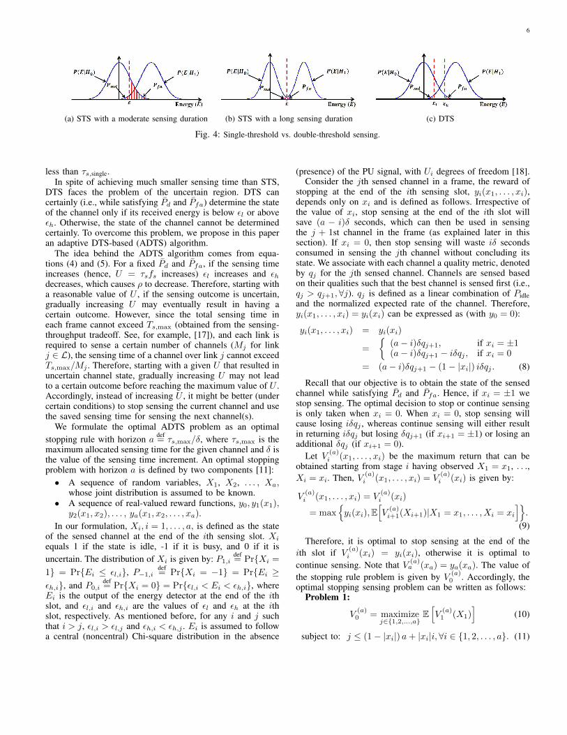
Using moderate sensing durations, STS cannot simultane-ously achieve low Pmd and low Pfa, as shown in Fig. 4. InFig. 4, P (E|H1) is the probability density function (pdf) of thereceived energy given that the channel is busy, and P (E|H0)is the pdf of the received energy given that the channel isidle. Fig. 4(a) shows that for a moderate sensing duration,and hence a moderate variance of the random variable E,STS cannot simultaneously guarantee low Pmd and low Pfa.Reducing the threshold ε reduces Pmd, but due to the directrelationship between Pmd and Pfa, Pfa increases. On the otherhand, increasing the sensing duration (and hence reducingthe variance of E) increases the possibility of simultaneouslysatisfying the required Pmd and Pfa, as shown in Fig. 4(b), butthis is undesirable as we intend to minimize the time spent inthe discovery phase. Accordingly, we resort to a DTS scheme,as shown in Fig. 4(c). DTS can simultaneously achieve lowPmd and low Pfa using a much smaller sensing time thanSTS. In DTS, εl is selected such that the required Pmd (whichequals to 1− Pd) is satisfied. On the other hand, εh is selectedto satisfy the required Pfa (which equals to Pfa). The relationsbetween εl and Pd, and εh and Pfa are given by:
εl(τs, Pd) = σ2n
[√2γ + 1
UQ−1(Pd) + γ + 1
](4)
εh(τs, Pfa) = σ2n
[√1
UQ−1(Pfa) + 1
]. (5)
The required sensing time to satisfy Pd and Pfa for STS andDTS schemes, denoted by τs,single and τs,double, respectively,can be easily expressed as [17]:
τs,single =1
γ2fs
[Q−1(Pfa)−Q−1(Pd)
√2γ + 1
]2(6)
τs,double =1
fs
[εh√
2γ + 1Q−1(Pd)− εlQ−1(Pfa)
εl − εh(γ + 1)
]2
.(7)
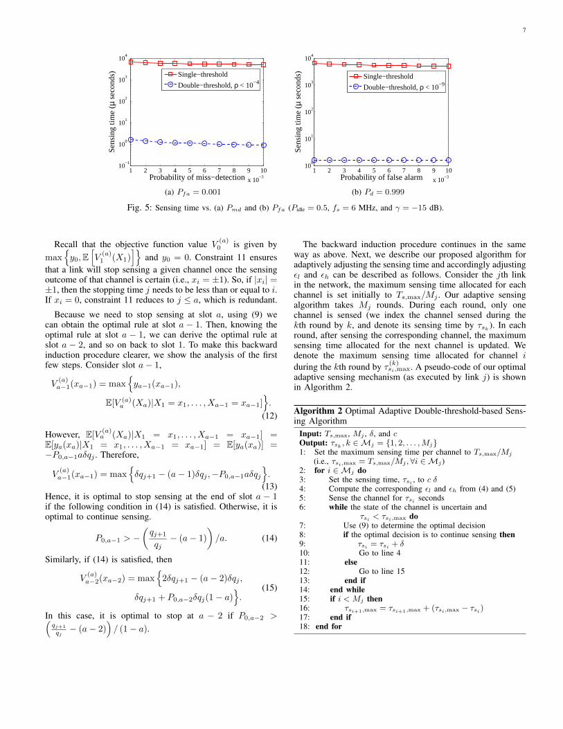
Let ρ denote the probability of uncertainty (i.e., the probabil-ity that the received energy over a given channel falls betweenεl and εh). Fig. 5 compares τs,single and τs,double for differentPd and Pfa values. It shows that for a given Pd and Pfa, andwith a small value of ρ, τs,double is 3 to 4 orders of magnitude
6
(a) STS with a moderate sensing duration (b) STS with a long sensing duration (c) DTS
Fig. 4: Single-threshold vs. double-threshold sensing.
less than τs,single.In spite of achieving much smaller sensing time than STS,
DTS faces the problem of the uncertain region. DTS cancertainly (i.e., while satisfying Pd and Pfa) determine the stateof the channel only if its received energy is below εl or aboveεh. Otherwise, the state of the channel cannot be determinedcertainly. To overcome this problem, we propose in this paperan adaptive DTS-based (ADTS) algorithm.
The idea behind the ADTS algorithm comes from equa-tions (4) and (5). For a fixed Pd and Pfa, if the sensing timeincreases (hence, U = τsfs increases) εl increases and εhdecreases, which causes ρ to decrease. Therefore, starting witha reasonable value of U , if the sensing outcome is uncertain,gradually increasing U may eventually result in having acertain outcome. However, since the total sensing time ineach frame cannot exceed Ts,max (obtained from the sensing-throughput tradeoff. See, for example, [17]), and each link isrequired to sense a certain number of channels (Mj for linkj ∈ L), the sensing time of a channel over link j cannot exceedTs,max/Mj . Therefore, starting with a given U that resulted inuncertain channel state, gradually increasing U may not leadto a certain outcome before reaching the maximum value of U .Accordingly, instead of increasing U , it might be better (undercertain conditions) to stop sensing the current channel and usethe saved sensing time for sensing the next channel(s).
We formulate the optimal ADTS problem as an optimalstopping rule with horizon a def
= τs,max/δ, where τs,max is themaximum allocated sensing time for the given channel and δ isthe value of the sensing time increment. An optimal stoppingproblem with horizon a is defined by two components [11]:• A sequence of random variables, X1, X2, . . . , Xa,
whose joint distribution is assumed to be known.• A sequence of real-valued reward functions, y0, y1(x1),
y2(x1, x2), . . . , ya(x1, x2, . . . , xa).In our formulation, Xi, i = 1, . . . , a, is defined as the state
of the sensed channel at the end of the ith sensing slot. Xi
equals 1 if the state is idle, -1 if it is busy, and 0 if it isuncertain. The distribution of Xi is given by: P1,i
def= Pr{Xi =
1} = Pr{Ei ≤ εl,i}, P−1,idef= Pr{Xi = −1} = Pr{Ei ≥
εh,i}, and P0,idef= Pr{Xi = 0} = Pr{εl,i < Ei < εh,i}, where
Ei is the output of the energy detector at the end of the ithslot, and εl,i and εh,i are the values of εl and εh at the ithslot, respectively. As mentioned before, for any i and j suchthat i > j, εl,i > εl,j and εh,i < εh,j . Ei is assumed to followa central (noncentral) Chi-square distribution in the absence
(presence) of the PU signal, with Ui degrees of freedom [18].Consider the jth sensed channel in a frame, the reward of
stopping at the end of the ith sensing slot, yi(x1, . . . , xi),depends only on xi and is defined as follows. Irrespective ofthe value of xi, stop sensing at the end of the ith slot willsave (a − i)δ seconds, which can then be used in sensingthe j + 1st channel in the frame (as explained later in thissection). If xi = 0, then stop sensing will waste iδ secondsconsumed in sensing the jth channel without concluding itsstate. We associate with each channel a quality metric, denotedby qj for the jth sensed channel. Channels are sensed basedon their qualities such that the best channel is sensed first (i.e.,qj > qj+1,∀j). qj is defined as a linear combination of Pidleand the normalized expected rate of the channel. Therefore,yi(x1, . . . , xi) = yi(xi) can be expressed as (with y0 = 0):
yi(x1, . . . , xi) = yi(xi)
=
{(a− i)δqj+1, if xi = ±1(a− i)δqj+1 − iδqj , if xi = 0
= (a− i)δqj+1 − (1− |xi|) iδqj . (8)
Recall that our objective is to obtain the state of the sensedchannel while satisfying Pd and Pfa. Hence, if xi = ±1 westop sensing. The optimal decision to stop or continue sensingis only taken when xi = 0. When xi = 0, stop sensing willcause losing iδqj , whereas continue sensing will either resultin returning iδqj but losing δqj+1 (if xi+1 = ±1) or losing anadditional δqj (if xi+1 = 0).
Let V (a)i (x1, . . . , xi) be the maximum return that can be
obtained starting from stage i having observed X1 = x1, . . .,Xi = xi. Then, V (a)
i (x1, . . . , xi) = V(a)i (xi) is given by:
V(a)i (x1, . . . , xi) = V
(a)i (xi)
= max{yi(xi),E
[V
(a)i+1(Xi+1)|X1 = x1, . . . , Xi = xi
]}.
(9)
Therefore, it is optimal to stop sensing at the end of theith slot if V
(a)i (xi) = yi(xi), otherwise it is optimal to
continue sensing. Note that V (a)a (xa) = ya(xa). The value of
the stopping rule problem is given by V (a)0 . Accordingly, the
optimal stopping sensing problem can be written as follows:Problem 1:
V(a)0 = maximize
j∈{1,2,...,a}E[V
(a)1 (X1)
](10)
subject to: j ≤ (1− |xi|) a+ |xi|i,∀i ∈ {1, 2, . . . , a}. (11)
7
1 2 3 4 5 6 7 8 9 10
x 10−3
10−1
100
101
102
103
104
Probability of miss−detection
Sen
sing
tim
e (µ
seco
nds)
Single−threshold
Double−threshold, ρ < 10−4
1 2 3 4 5 6 7 8 9 10
x 10−3
100
101
102
103
104
Probability of false alarm
Sen
sing
tim
e (µ
seco
nds)
Single−threshold
Double−threshold, ρ < 10−9
(a) Pfa = 0.001 (b) Pd = 0.999
Fig. 5: Sensing time vs. (a) Pmd and (b) Pfa (Pidle = 0.5, fs = 6 MHz, and γ = −15 dB).
Recall that the objective function value V(a)0 is given by
max{y0,E
[V
(a)1 (X1)
]}and y0 = 0. Constraint 11 ensures
that a link will stop sensing a given channel once the sensingoutcome of that channel is certain (i.e., xi = ±1). So, if |xi| =±1, then the stopping time j needs to be less than or equal to i.If xi = 0, constraint 11 reduces to j ≤ a, which is redundant.
Because we need to stop sensing at slot a, using (9) wecan obtain the optimal rule at slot a − 1. Then, knowing theoptimal rule at slot a − 1, we can derive the optimal rule atslot a − 2, and so on back to slot 1. To make this backwardinduction procedure clearer, we show the analysis of the firstfew steps. Consider slot a− 1,
V(a)a−1(xa−1) = max
{ya−1(xa−1),
E[V (a)a (Xa)|X1 = x1, . . . , Xa−1 = xa−1]
}.
(12)
However, E[V(a)a (Xa)|X1 = x1, . . . , Xa−1 = xa−1] =
E[ya(xa)|X1 = x1, . . . , Xa−1 = xa−1] = E[ya(xa)] =−P0,a−1aδqj . Therefore,
V(a)a−1(xa−1) = max
{δqj+1 − (a− 1)δqj ,−P0,a−1aδqj
}.
(13)Hence, it is optimal to stop sensing at the end of slot a − 1if the following condition in (14) is satisfied. Otherwise, it isoptimal to continue sensing.
P0,a−1 > −(qj+1
qj− (a− 1)
)/a. (14)
Similarly, if (14) is satisfied, then
V(a)a−2(xa−2) = max
{2δqj+1 − (a− 2)δqj ,
δqj+1 + P0,a−2δqj(1− a)}.
(15)
In this case, it is optimal to stop at a − 2 if P0,a−2 >(qj+1
qj− (a− 2)
)/ (1− a).
The backward induction procedure continues in the sameway as above. Next, we describe our proposed algorithm foradaptively adjusting the sensing time and accordingly adjustingεl and εh can be described as follows. Consider the jth linkin the network, the maximum sensing time allocated for eachchannel is set initially to Ts,max/Mj . Our adaptive sensingalgorithm takes Mj rounds. During each round, only onechannel is sensed (we index the channel sensed during thekth round by k, and denote its sensing time by τsk ). In eachround, after sensing the corresponding channel, the maximumsensing time allocated for the next channel is updated. Wedenote the maximum sensing time allocated for channel iduring the kth round by τ (k)
si,max. A pseudo-code of our optimaladaptive sensing mechanism (as executed by link j) is shownin Algorithm 2.
Algorithm 2 Optimal Adaptive Double-threshold-based Sens-ing Algorithm
Input: Ts,max, Mj , δ, and cOutput: τsk , k ∈Mj = {1, 2, . . . ,Mj}1: Set the maximum sensing time per channel to Ts,max/Mj
(i.e., τsi,max = Ts,max/Mj ,∀i ∈Mj)2: for i ∈Mj do3: Set the sensing time, τsi , to c δ4: Compute the corresponding εl and εh from (4) and (5)5: Sense the channel for τsi seconds6: while the state of the channel is uncertain and
τsi < τsi,max do7: Use (9) to determine the optimal decision8: if the optimal decision is to continue sensing then9: τsi = τsi + δ10: Go to line 411: else12: Go to line 1513: end if14: end while15: if i < Mj then16: τsi+1,max = τsi+1,max + (τsi,max − τsi)17: end if18: end for

8
Fig. 6: An illustrative example for the adaptive sensing algo-rithm.
Fig. 6 shows an illustrative example for the adaptive sensingalgorithm, where the number of channels to be sensed is 4.Initially, each channel is allocated a maximum sensing time ofTs,max/4, which is assumed in this example to be equal to 5δ.The first channel is sensed in the first round and its sensingtime τs1 is determined according to the above algorithm. Inour example, τs1 is assumed to be 3δ (i.e., 2δ less than themaximum allocated sensing time). The saved 2δ seconds areallocated for the next channel, so that the maximum sensingtime for the second channel becomes 5δ + 2δ = 7δ. Theremaining three rounds continue in the same way.
Remark 1: In the above formulation of the optimal ADTSscheme (Problem 1), we require a link to stop sensing a givenchannel once the state of this channel is certain (i.e., idle orbusy while satisfying the required Pmd and Pfa). Our objectivein Problem 1 is to minimize the per-channel sensing time (andhence maximize the total number of sensed channels) subjectto satisfying the required Pmd and Pfa.
Another ADTS scheme can be formulated by incorporatingPmd and Pfa into the optimization objective (in addition to theconstraints). In this case, the objective is to maximize the totalnumber of sensed channels that result in a certain outcome(hence, satisfy the minimum requirements on Pmd and Pfa)as well as minimize Pmd and Pfa. Therefore, even if thesensing outcome of a given channel at the end of the ith slot iscertain (i.e., xi = ±1), a link may decide to continue sensingthis particular channel; because this will improve its sensingaccuracy (i.e., achieve lower values of Pmd and Pfa). We referto this version of the ADTS scheme as optimal ADTS withenhanced accuracy (ADTSEA). The optimal ADTSEA can be
formulated by modifying the stopping reward in (8) as follows:
yi(x1, . . . , xi) = yi(xi)
=
{(a− i)δqj+1 + (1− Pmd) (1− Pfa) , if xi = ±1(a− i)δqj+1 − iδqj , if xi = 0.
(16)
Consider the case when xi = ±1. Note from (16) thatalthough the first term in yi(xi) decreases with i, the secondterm increases with i (both Pmd and Pfa decrease with thesensing time). Because in optimal ADTSEA a link mightcontinue sensing a given channel after its state being certain,constraint (11) in Problem 1 is removed in the case ofADTSEA.
In our current framework, we aim to maximize the amountof discovered opportunities subject to stringent requirementson PU protection, rather than optimizing the sensing accuracy.Therefore, in this paper we focus on the optimal ADTSscheme.
B. Scheduling of Sensing/Probing Processes for HP FlowsIn [2], an access point and spectral band selection scheme,
called MAWS, is proposed. In this scheme, the channel qualityis inferred by periodically probing random spectral bandswithout any proper scheduling mechanism. However, in ourscheme, while scheduling the sensing/probing processes forlinks transporting HP flows, we probabilistically guarantee theaggregate bandwidth of the discovered opportunities by eachlink j to be equal to R(j)
d + κ, where κ < R(j)d . The rationale
behind this approach is two-fold; to include the impact offluctuations in channel quality, and to ensure serving the linksthat carry LP flows in the network using the excess discoveredopportunities. Although the effect of mobility is indirectlybeing captured through the coherence time, it is very hard toguarantee the validity of the estimated channel quality withlapse in time. We assume that this quality does not varydrastically in a short interval of time. Hence, for any link j
with rate demand R(j)d , we choose κ such that κ < R
(j)d .
We formulate our scheduling problem as a constrainedoptimization problem with the objective of maximizing thenumber of HP flows with satisfied rate demands. Let N(|N | = N) be the set of channels that are considered forsensing/probing scheduling, and let L (|L| = L) be the set oflinks that will participate in the sensing/probing process. Lety
(j)i , i ∈ N , j ∈ L, be a binary variable which equals 1 if
channel i is scheduled to be sensed/probed by link j, and 0otherwise. Let R(j)
i be the rate supported by channel i overlink j, and Θ
(j)i
def= y
(j)i R
(j)i P
(i)idle(t). Then, our optimization
problem can be formulated as a non-linear binary program asfollows:
Problem 2:
maximizey(j)i
i∈N ,j∈L
∑j∈L
1{∑i∈N Θ
(j)i >R
(j)d +κ
} +
∑i∈Nj∈L
y(j)i R
(j)i∑
i∈Nj∈L
y(j)i Rmax
(17)

9
subject to:∑j∈L
y(j)i ≤ 1,∀i ∈ N (18)
∑i∈N
y(j)i ≤Mj ,∀j ∈ L (19)
where Rmax is the maximum supported data rate by anychannel i ∈ N , and 1{·} is the indicator function. Thefirst term in the objective function indicates that we wish tomaximize the number of satisfied HP flows through parallelsensing/probing. The second term is intended to resolve the tiein case of multiple optimal solutions. The second term alwayshas a value ≤ 1. Constraint (18) ensures that no channel canbe sensed/probed by more than one link in a given frame.Constraint (19) restricts the maximum number of channelsthat can be sensed/probed by link j to a predefined value Mj .Inoperable links whose requested rate demands cannot be metare made to sense the channels whose PU state is undeterminedto prevent the occurrence of a “starvation” condition. Con-straints (18) and (19) can be written in matrix form as A~y ≤ ~b,where A = (aij)1≤i≤N+L,1≤j≤NL, ~y = (y
(j)i )i∈N ,j∈L, and
~b = (1, . . . , 1,M1, . . . ,ML)T ∈ RN+L.Proposition 1. Matrix A in Problem 2 is totally unimodular
(TU) [19]. This means that the decision variables y(j)i can be
relaxed to continuous variables, and the resulted solution toProblem 2 is still optimal.
Proof: It can be seen that: (i) aij ∈ {0, 1}, (ii) eachcolumn in A contains at most two nonzero coefficients (i.e.,∑N+Li=1 |aij | ≤ 2), and (iii) there exists a partition (M1 =
{1, . . . , N},M2 = {N + 1, . . . , N + L}) of rows such thateach column j containing two nonzero coefficients satisfies:∑i∈M1
aij−∑i∈M2
aij = 0. Since the above three conditionsare satisfied, matrix A is TU [19].
C. Sensing/Probing Scheduling with Additional Practical Con-straints
In existing channel aggregation systems, a device cannotaggregate two channels if the frequency separation betweenthese channels exceeds a certain threshold. In this section, wemodify the sensing/probing scheduling scheme formulated inProblem 2 to account for this additional hardware constraint.
The channel aggregation constraint can be stated as follows:∀l, k ∈ N and ∀j ∈ L, if |l − k| > B then y
(j)l + y
(j)k ≤ 1,
where B is the maximum allowable separation between the ag-gregated frequency channels. To formally write this constraint,we introduce the following binary variables:
dl,k =
{1, if |l − k| > B0, otherwise ,∀l, k ∈ N ,∀j ∈ L
e(j)l,k =
{1, if y(j)
l + y(j)k ≤ 1
0, otherwise,∀l, k ∈ N ,∀j ∈ L.
(20)
Then, the constraint can be written as dl,k ≤ e(j)l,k ,∀l, k ∈
N ,∀j ∈ L. Next, we present a simplified way of representingthe binary variables in (20).
1. dl,k = 1 iff |l − k| > B can be reformulated as follows:• if |l−k| > B then dl,k = 1 can be equivalently written
as |l − k| − (M + 1) dl,k ≤ B − 1, where M is anupper bound of |l − k| − B.
• if dl,k = 1 then |l−k| > B can be equivalently writtenas |l−k|+mdl,k ≥ m+B, where m is a lower boundof |l − k| − B.
Because 1 ≤ |l − k| ≤ N , we set M and m to N − Band 1 − B, respectively. Hence, ‘dl,k = 1 iff |l − k| > B’can be equivalently written as: (B − 1) dl,k + 1 ≤ |l−k| ≤(N − B + 1
)dl,k + B − 1.
2. Similar to point 1 above, e(j)l,k = 1 iff y(j)
l + y(j)k ≤ 1 can
be reformulated as follows:• if y(j)
l + y(j)k ≤ 1 then e
(j)l,k = 1 can be equivalently
written as 2− y(j)l − y
(j)k ≤ 2e
(j)l,k .
• if e(j)l,k = 1 then y
(j)l + y
(j)k ≤ 1 can be equivalently
written as 2− y(j)l − y
(j)k ≥ e
(j)l,k .
Hence, ‘e(j)l,k = 1 iff y(j)
l + y(j)k ≤ 1’ can be equivalently
written as: e(j)l,k ≤ 2− y(j)
l − y(j)k ≤ 2e
(j)l,k .
Accordingly, to account for the additional channel aggrega-tion constraint, we add the following constraints to Problem2:
(B − 1)dl,k + 1 ≤ |l − k|≤(N − B + 1
)dl,k + B − 1,∀l, k ∈ N (21)
e(j)l,k ≤ 2− y(j)
l − y(j)k ≤ 2e
(j)l,k ,∀l, k ∈ N ,∀j ∈ L (22)
dl,k ≤ e(j)l,k ,∀l, k ∈ N ,∀j ∈ L (23)
dl,k, e(j)l,k ∈ {0, 1},∀l, k ∈ N ,∀j ∈ L. (24)
VI. ALLOCATION OF DATA CHANNELS
In this section, we propose an efficient data channel assign-ment algorithm, which incorporates channel aggregation andbonding techniques. Our objective is to minimize the numberof channels allocated to any HP link, in an attempt to maximizethe number of admitted flows in the network.
A. Channel Assignment AlgorithmSeveral wireless protocol designs have been proposed to
improve the spatial reuse of the network (e.g., [6]–[8]). Inaddition to maximize the network’s spatial reuse, our problemis further complicated by the need to meet the rate demands ofthe HP flows and guarantee interference-free communicationfor PUs. The proposed channel assignment algorithm attemptsto overcome these challenges by exploiting the available re-sources (channels) to the maximum extent.
Given the sensing/probing outcomes provided by the activelinks, the MD initially computes the feasibility of supportingthe rate demands of each HP flow using the channels whichwere sensed to be idle by the corresponding link. Let Kj(|Kj | = Kj) be the set of idle channels discovered by link

10
j. The MD checks if∑Kj
i=1R(j)i > R
(j)d . If this condition is
satisfied, the MD executes Problem 3 below to compute theoptimal number of channels needed to support the rate demandon that link. The links that do not meet the above conditionare classified as unsatisfied links. Let x(j)
i , i ∈ Kj , be a binaryvariable which equals 1 if channel i is assigned to link j, and0 otherwise. Our optimization problem is stated as follows.
Problem 3:
minimizex(j)i ,i∈Kj
∑i∈Kj
x(j)i +
∑i∈Kj
x(j)i R
(j)i∑
i∈Kjx
(j)i Rmax
(25)
subject to:∑i∈Kj
x(j)i R
(j)i ≥ R
(j)d . (26)
Problem 3 is a non-linear binary program. The objectivefunction aims at minimizing the number of channels to beallocated for a given link while meeting the requested ratedemand. The second term in the objective function is usedto break the ties among multiple optimal solutions. Whenmultiple optimal solutions exist, our formulation ensures theselection of channels with minimum aggregated data rate, suchthat the remaining channel(s) can be used during the secondround of channel probing to support other unsatisfied links inthe network.
B. Channel Assignment Algorithm with Additional PracticalConstraints
In this section, we modify the channel assignment schemeformulated in Problem 3 to account for two additional con-straints: (i) a link cannot aggregate two channels if the fre-quency separation between these channels exceeds B, and (ii)it cannot bond/aggregate more than C channels. Similar toSection V-C, to meet the first requirement we add the followingconstraints to Problem 3:
(B − 1)wl,k + 1 ≤ |l − k|≤ (Kj − B + 1)wl,k + B − 1,∀l, k ∈ Kj
(27)
v(j)l,k ≤ 2− x(j)
l − x(j)k ≤ 2v
(j)l,k ,∀l, k ∈ Kj (28)
wl,k ≤ v(j)l,k ,∀l, k ∈ Kj (29)
wl,k, v(j)l,k ∈ {0, 1},∀l, k ∈ Kj . (30)
To meet the second requirement, we add the followingconstraint to Problem 3:∑
i∈Kj
x(j)i ≤ C. (31)
C. Second Round of Channel ProbingTo meet the rate demand of an unsatisfied link, we first
compute the maximum data rate that can be supported by itschannel set, i.e., the channels that were sensed/probed by thatlink. Consequently, we schedule this link for a second round ofprobing over the channels that have been deemed excess by thesatisfied links in the network. More specifically, we allocate a
Fig. 7: Example illustrating the second round probing process.
total of 3 MASs before the start of a data transmission in S,S/P-1, and S/P-2 frames for the second round probing, whereina maximum of one channel can be probed by any unsatisfiedlink in the network. If the rate demand of the HP flow canbe satisfied by combining the channels in its own channel setand the newly probed channel, the receiver sends a positivefeedback to the transmitter, after which the transmitter startssending data by aggregating/bonding these channels.
In our design, we assume the presence of several linkscarrying LP flows throughout the operation of the network. Weare interested in supporting LP alongside HP flows. The drasticincrease in the number of discovered opportunities brought inby QASPA always guarantees fair share of bandwidth for theLP flows. Note that, LP flows have no stringent bandwidthrequirement, which permits us to assign channels to these flowsregardless of their exhibited quality. The idle channels whichare not assigned to HP flows are used by LP flows.
As an example for the second round probing, considertwo links l1 and l2 with rate demands of 10 and 7 Mbps,respectively, as illustrated in Fig. 7. Assume that the amountof bandwidth discovered by these two links during their sens-ing/probing phase are 7 and 5 Mbps, respectively. Hence, theirrate demands were not met using the discovered opportunities,making these links inoperable. Assume that h5 and h7 are thechannels that have been deemed excess by the satisfied linksin the network. We randomly assign h5 to l1 and h7 to l2 forprobing. We allocate channels in a random fashion because wedo not know the link-dependent channel quality informationahead of time. Assume that h5 can support 4 Mbps over l1 andh7 can support 2 Mbps over l2. Hence, we are able to satisfythe rate demand of l1, whereas the rate demand of l2 remainsunsatisfied. This way, we are able to increase the number ofsatisfied links at the cost of second round of probing.
Next, we discuss two important aspects in our protocol: thecontrol channel selection, and the adaptive reporting strategy.
Common Control Channel (CCC) Selection–The depen-dance on a dedicated CCC for control packets exchange hasbeen an impending issue since the inception of CRNs. UnlikeISM bands, TVWS communication demands guarantee oninterference-free communication for the PUs. This requirementcurbs the use of any channel in the licensed TVWS forcommunicating control/management information without theknowledge of its current state (idle/busy). The other issue inmaintaining a network-wide CCC in a multi-channel systemis synchronization (i.e., all SUs need to rendezvous during

11
the time of control packets exchange), which requires anappropriate signaling mechanism. By exploiting the propertiesof quorum systems, several distributed rendezvous schemeshave been proposed in the literature (see, for example, [20]–[24] and references therein).
In here, we exploit the centralized architecture to maintaina time-varying CCC using the estimated PU profiles. Theselection of a channel as a CCC depends on its PU state ratherthan its quality, as control packets are transmitted at the lowestrate. In the current frame, let H be the set of channels whoseToff > Tframe + µ, where µ (< Tframe) is a small quantity thataccounts for discrepancy in the estimated values of Toff. WithinH, the idle channel with the highest probability of remainingidle during the next frame is selected as a CCC. The selectedCCC is broadcasted by the MD during the BP at the end ofthe current frame.
Adaptive Reporting Strategy–Motivated by the highswitching speeds of the A/D converters deployed in softwaredefined radio front-ends [25], we propose an adaptive reportingstrategy wherein the time allocated to the reporting phase(Trep) is decided dynamically based on the number of channelsscheduled for sensing/probing. Assume that r channels werescheduled by the MD. We equally divide Trep into r sub-slots,one for each channel. In addition, the MD broadcasts a hoppingsequence to rendezvous with the devices to gather the reportpackets. This hopping sequence information is encapsulatedin the sensing/probing scheduling packet. Assume that thehopping sequence is C1, C2, . . . , Cr. The MD tunes to channelCi during the ith sub-slot. Suppose that channel i is scheduledfor sensing/probing by link j. If channel i is sensed to be idle,it will be probed. The destination device of link j will thensend a control packet to the MD, containing the PU state ofthe channel along with its quality (in case of successful probepacket exchange) during the ith sub-slot. Note that if a channelwas sensed to be busy by link j, no control packet is sentduring the ith sub-slot. Consequently, the MD interprets thischannel to be occupied, and excludes it when assigning chan-nels for data communication. The major accomplishment inthis reporting strategy is the elimination of channel contentiondelay, which might hinder the timely exchange of vital controlinformation. The MD waits for trep
def= Trep/r at each sub-slot
for hearing any control packets from the associated SUs. If thistime expires, the MD gracefully moves to the next sub-slot inTrep.
VII. PERFORMANCE EVALUATION
A. Evaluation SetupWe consider an area of 50 × 50 m2, mimicking an indoor
environment. We consider 40 channels in the UHF band, eachof 6 MHz bandwidth. Each channel can support one of fiverates viz. 2, 4, 8, 12, and 16 Mbps, each with probability 0.2.This randomness in the channel data rate captures wirelessphenomena like fading, shadowing, and RF interference in oursimulations. We use the approximation used in [26] to captureτc in our simulations. Specifically, τc(t) = 9λ
16πv(t) , wherev(t) represents the velocity of the CR transmitter towards theintended CR receiver along the line of sight, and λ = c
fc
TABLE I: Durations of various operations in the TDMA frame.
Operation Duration Operation Duration(MAS) (MAS)
Association 5 Channel Reporting 25Beacon Period 2 Channel Assignment 2S/P Scheduling 2 Second-round Probing 3
represents the wavelength of the signal corresponding to thecarrier frequency fc. We vary τc uniformly between 1 and 10secs. Ton = Toff = 5 secs.
As elucidated earlier, we resort to a frame-based time-slottedprotocol. The time slots can be described at the medium-access level using MASs, with the duration of each MASdefined to be 1 msec in our setup. The fixed number ofMASs allocated for each operation in our TDMA frame isillustrated in Table I. Tframe = 250 MASs. Each link carryingHP flow is randomly assigned a rate demand between 5 and15 Mbps. The rate demands of the HP flows are updatedonce they complete transferring their video flows of predefineddurations, as dictated by the video trace-files. Pd and Pfa areset to 0.9 and 0.25, respectively. β in Section IV is set to0.75. All LP flows are composed of constant bit rate (CBR)traffic with constant data-packet size of 1 K byte. We usea 500 byte control packet. All simulations are carried outfor 10000 frames using CSIM (a C-based process-orienteddiscrete-event simulation package), and reported values arethe average of 20 runs. The optimization problems are solvedusing MATLAB. Our simulations are conducted to evaluatethe performance gain resulted from the interactions betweenthe various proposed components: QASPA, AFS, and theadaptive channel assignment strategy. All the three componentscontribute to the enhancement in the network performanceachieved by the proposed protocol.
B. Evaluation of QASPA1) Impact of QASPA on Discovery Efficiency: We study the
discovery efficiency, defined as the number of idle channelsdiscovered per unit time, achieved by QASPA and contrastit with a random scheduling scheme which does not makeuse of the estimated PU profiles and prior channel qualityinformation while scheduling links for sensing/probing. Thisrandom scheduling is very similar to the channel probingscheme in [2]. Note that we allow unique sets of channels tobe sensed/probed by individual links even under the randomscheduling scheme, so as to prevent probe packet collisionduring the spectrum discovery phase. Ts,max = 20 msecs andκ = 2 Mbps. Rd = 3 Mbps for all HP flows. Fig. 8 shows thatthe number of operational links has a profound impact on thediscovery efficiency. Operation of sensing/probing processesin parallel boosts the discovery efficiency significantly. Incontrast, random scheduling, despite being facilitated withparallel sensing/probing, fail to match the efficiency of QASPAdue to the lack of knowledge on PUs profiles.
It is to be noted that the increase in discovery efficiency isalso heavily attributed to the optimal ADTS scheme. To verify

12
this, we compare the discovery efficiency of STS, DTS, andthe proposed ADTS and optimal ADTS schemes, for a single-link scenario under various values of Ts,max. DTS scheme usesa fixed per-channel sensing duration. The uncertain region inDTS prevents us from accurately deciphering the PU state ofthe channel, and as a conservative approach we deem thesechannels to be busy. This results in lower discovery efficiency,as several channels, which might be idle, are deemed occu-pied. We break this norm in our ADTS scheme, wherein weuse an adaptive per-channel sensing duration which helps usto accurately identify the PU state of the channel, therebyleading to improved sensing efficiency (defined as the ratiobetween the number of idle channels and the total numberof channels sensed during Ts,max), as seen in Fig. 9. Ouroptimal ADTS scheme further improves the sensing efficiencyby optimizing the sensing time. In contrast to STS, ADTS,and optimal ADTS, the sensing efficiency of DTS changesabruptly with the discovery time. This happens because ofthe uncertainty region. With slight changes in the discoverytime, several channels that had ‘certain’ states might fall in theuncertainty region, and vice versa. Although the uncertaintyregion also exists in the ADTS and ‘optimal ADTS’ schemes,the adaptability of the maximum per-channel sensing time inthese schemes makes them immune to such abrupt changes.
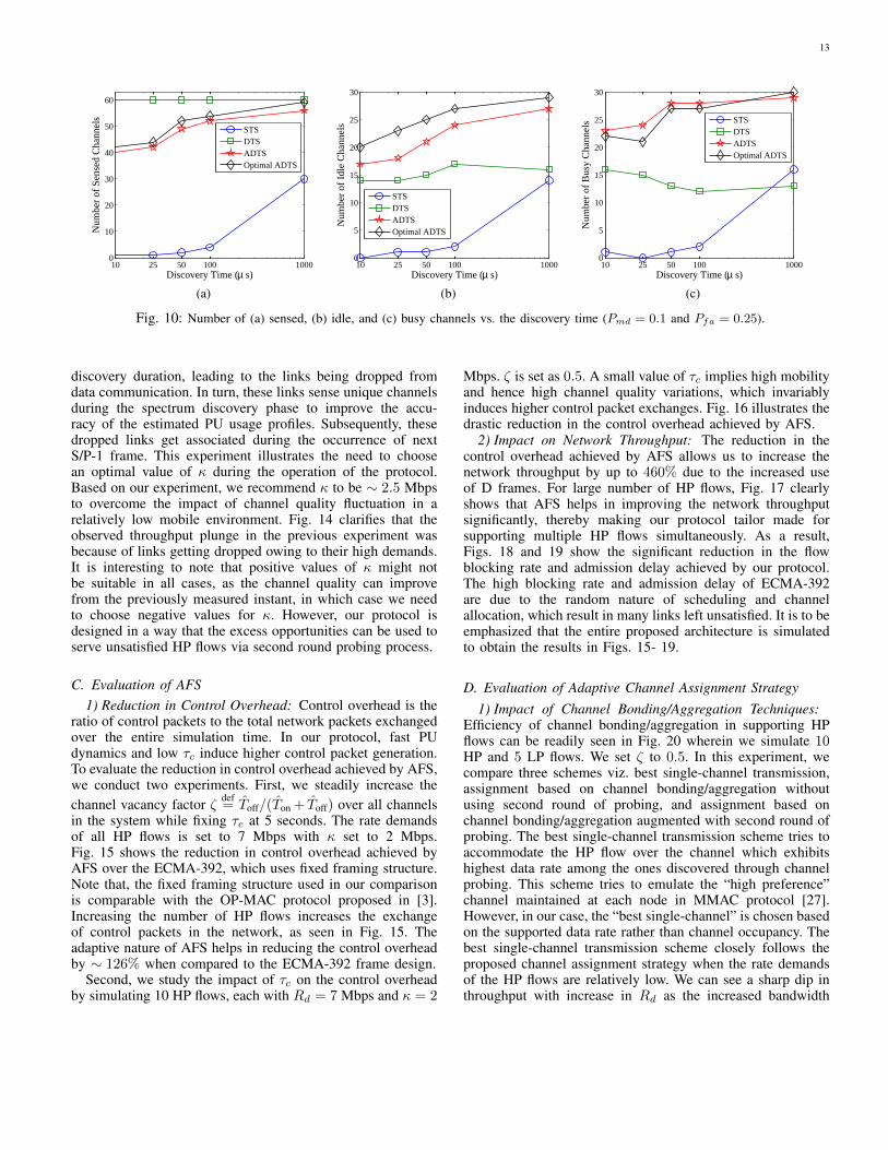
In Fig. 10, we provide a more detailed comparison betweenthe various sensing schemes. The total number of channels inthe system is 60. Fig. 10(a) shows the total number of sensedchannels as a function of the discovery time when Pmd =0.1 and Pfa = 0.25. Fig. 10(b) shows the number of sensedchannels that are found idle and Fig. 10(c) shows the numberof sensed channels that are found busy (both as a function ofthe discovery time). It is important to note that in contrast to allother sensing schemes, the sum of the idle and busy channels inthe DTS scheme does not equal to the total number of sensedchannels. In DTS, some of the sensed channels are neither idlenor busy (i.e., the total received energy over these channelsfalls in the uncertainty region). As shown in Fig. 10, the totalnumber of sensed channels that result in a certain outcome(i.e., the number of idle channels, shown in Fig. 10(a), plus thenumber of busy channels, shown in Fig. 10(b)) is significantlyhigher in ADTS compared to STS and DTS. Optimal ADTSfurther improves this total number of sensed channels with acertain outcome compared to ADTS. Note from Fig. 10(a) thatin DTS all channels can be sensed within 10µs while satisfyingthe required Pmd and Pfa (this is inline with Fig. 5). In theother sensing schemes (STS, ADTS, and optimal ADTS), thenumber of sensed channels increases with the discovery time.As shown in Fig. 10(a), the number of sensed channels in STSis very small because it requires a significantly larger sensingtime to satisfy the required Pmd and Pfa compared to theDTS-based schemes (i.e., DTS, ADTS, and optimal ADTS).
Next, we compute the bandwidth discovered by QASPAto illustrate the impact of considering the channel quality inthe sensing/probing scheduling. In this experiment, we fix thenumber of HP flows to 10, and vary Rd of each HP flow from5 to 15 Mbps. Fig. 11 shows that the bandwidth discoveredby random scheduling is much less than that of QASPA.Fig. 12 shows the significant reduction in the flow blocking
2 4 6 8 10 120
0.2
0.4
0.6
0.8
1
1.2
1.4
1.6
1.8
2
Number of active links
Dis
cove
ry e
ffic
ienc
y
QASPARandom scheduling
Fig. 8: Discovery efficiency of QASPA (Ts,max = 20 msecs andκ = 2 Mbps. Rd = 3 Mbps for all HP flows).
20 25 30 35 40 45 50 55 60600.1
0.15
0.2
0.25
0.3
0.35
0.4
0.45
0.5
Discovery time (msec)
Sens
ing
effi
cien
cy
STSDTSADTSOptimal ADTS
Fig. 9: Sensing efficiency (Ts,max = 20 msecs and κ = 2 Mbps.Rd = 3 Mbps for all HP flows).
rate achieved by QASPA as a function of Rd.Unlike other related works, we propose a complete end-to-
end architecture to support bandwidth-intensive applicationsin CRNs. To the best of our knowledge, this is the firstwork to propose one such comprehensive solution to supporthigh-bandwidth communications in CRNs. Thus, in order toaccurately project the efficiency of our overall architecture, wehad to compare the proposed components of our architecturewith base models.
2) Impact of κ on QASPA: κ plays a very important role inmobile wireless networks, wherein the quality of the channelchanges frequently due to node mobility. To evaluate theimpact of κ on network throughput, we consider 10 HP and 5LP flows. Ts,max is set to 20 milliseconds. Fig. 13 illustratesthe impact of κ on the network throughput for two differentrate demands. It is clear that the network throughput exhibitsan upward trend for increasing κ in both scenarios until itreaches a breaking point, beyond which it starts decreasing.
Increasing κ beyond a certain limit prevents the schedulerfrom scheduling channels for the links to discover the highbandwidth requirement of Rd + κ in a restricted spectrum
13
10 25 50 100 10000
10
20
30
40
50
60
Discovery Time (µ s)
Num
ber
of S
ense
d C
hann
els
STSDTSADTSOptimal ADTS
10 25 50 100 10000
5
10
15
20
25
30
Discovery Time (µ s)
Num
ber
of I
dle
Cha
nnel
s
STSDTSADTSOptimal ADTS
10 25 50 100 10000
5
10
15
20
25
30
Discovery Time (µ s)
Num
ber
of B
usy
Cha
nnel
s
STSDTSADTSOptimal ADTS
(a) (b) (c)
Fig. 10: Number of (a) sensed, (b) idle, and (c) busy channels vs. the discovery time (Pmd = 0.1 and Pfa = 0.25).
discovery duration, leading to the links being dropped fromdata communication. In turn, these links sense unique channelsduring the spectrum discovery phase to improve the accu-racy of the estimated PU usage profiles. Subsequently, thesedropped links get associated during the occurrence of nextS/P-1 frame. This experiment illustrates the need to choosean optimal value of κ during the operation of the protocol.Based on our experiment, we recommend κ to be ∼ 2.5 Mbpsto overcome the impact of channel quality fluctuation in arelatively low mobile environment. Fig. 14 clarifies that theobserved throughput plunge in the previous experiment wasbecause of links getting dropped owing to their high demands.It is interesting to note that positive values of κ might notbe suitable in all cases, as the channel quality can improvefrom the previously measured instant, in which case we needto choose negative values for κ. However, our protocol isdesigned in a way that the excess opportunities can be used toserve unsatisfied HP flows via second round probing process.
C. Evaluation of AFS1) Reduction in Control Overhead: Control overhead is the
ratio of control packets to the total network packets exchangedover the entire simulation time. In our protocol, fast PUdynamics and low τc induce higher control packet generation.To evaluate the reduction in control overhead achieved by AFS,we conduct two experiments. First, we steadily increase thechannel vacancy factor ζ def
= Toff/(Ton + Toff) over all channelsin the system while fixing τc at 5 seconds. The rate demandsof all HP flows is set to 7 Mbps with κ set to 2 Mbps.Fig. 15 shows the reduction in control overhead achieved byAFS over the ECMA-392, which uses fixed framing structure.Note that, the fixed framing structure used in our comparisonis comparable with the OP-MAC protocol proposed in [3].Increasing the number of HP flows increases the exchangeof control packets in the network, as seen in Fig. 15. Theadaptive nature of AFS helps in reducing the control overheadby ∼ 126% when compared to the ECMA-392 frame design.
Second, we study the impact of τc on the control overheadby simulating 10 HP flows, each with Rd = 7 Mbps and κ = 2
Mbps. ζ is set as 0.5. A small value of τc implies high mobilityand hence high channel quality variations, which invariablyinduces higher control packet exchanges. Fig. 16 illustrates thedrastic reduction in the control overhead achieved by AFS.
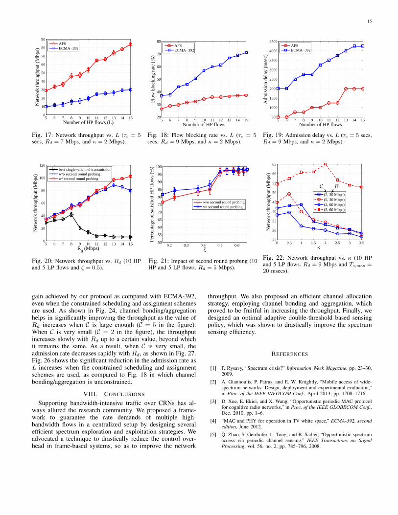
2) Impact on Network Throughput: The reduction in thecontrol overhead achieved by AFS allows us to increase thenetwork throughput by up to 460% due to the increased useof D frames. For large number of HP flows, Fig. 17 clearlyshows that AFS helps in improving the network throughputsignificantly, thereby making our protocol tailor made forsupporting multiple HP flows simultaneously. As a result,Figs. 18 and 19 show the significant reduction in the flowblocking rate and admission delay achieved by our protocol.The high blocking rate and admission delay of ECMA-392are due to the random nature of scheduling and channelallocation, which result in many links left unsatisfied. It is to beemphasized that the entire proposed architecture is simulatedto obtain the results in Figs. 15- 19.
D. Evaluation of Adaptive Channel Assignment Strategy1) Impact of Channel Bonding/Aggregation Techniques:
Efficiency of channel bonding/aggregation in supporting HPflows can be readily seen in Fig. 20 wherein we simulate 10HP and 5 LP flows. We set ζ to 0.5. In this experiment, wecompare three schemes viz. best single-channel transmission,assignment based on channel bonding/aggregation withoutusing second round of probing, and assignment based onchannel bonding/aggregation augmented with second round ofprobing. The best single-channel transmission scheme tries toaccommodate the HP flow over the channel which exhibitshighest data rate among the ones discovered through channelprobing. This scheme tries to emulate the “high preference”channel maintained at each node in MMAC protocol [27].However, in our case, the “best single-channel” is chosen basedon the supported data rate rather than channel occupancy. Thebest single-channel transmission scheme closely follows theproposed channel assignment strategy when the rate demandsof the HP flows are relatively low. We can see a sharp dip inthroughput with increase in Rd as the increased bandwidth

14
5 6 7 8 9 10 11 12 13 14 151530
40
50
60
70
80
90
100
110
120
Rd (Mbps)
Dis
cove
red
rate
(M
bps)
QASPARandom scheduling
Fig. 11: Bandwidth discovered by QASPA(L = 10).
5 6 7 8 9 10 11 12 13 14 15150
10
20
30
40
50
60
70
80
Rd (Mbps)
Flow
blo
ckin
g ra
te (
%)
QASPARandom scheduling
Fig. 12: Flow blocking rate vs. Rd (L = 10).
0 0.5 1 1.5 2 2.5 3 3.5 4420
30
40
50
60
70
80
90
κ
Net
wor
k th
roug
hput
(M
bps)
QASPA (Rd = 7 Mbps)
QASPA (Rd = 9 Mbps)
Fig. 13: Network throughput vs. κ (10 HPand 5 LP flows. Ts,max = 20 msecs).
0 0.5 1 1.5 2 2.5 3 3.5 4440
50
60
70
80
90
100
κ
Adm
issi
on r
ate
(%)
QASPA (Rd = 7 Mbps)
QASPA (Rd = 9 Mbps)
Fig. 14: Admission rate vs. κ (10 HP and 5LP flows. Ts,max = 20 msecs).
5 7 9 11 13 150
0.2
0.4
0.6
0.8
1
Number of HP flows (L)
Con
trol
ove
rhea
d
AFS (ζ = 0.2)AFS (ζ = 0.6)AFS (ζ = 0.7)ECMA−392 (ζ = 0.2)ECMA−392 (ζ = 0.6)ECMA−392 (ζ = 0.7)
Fig. 15: Control overhead vs. L (τc = 5 secs,Rd = 7 Mbps, and κ = 2 Mbps).
1 2 3 4 5 6 7 8 9 10100.1
0.2
0.3
0.4
0.5
0.6
0.7
0.8
0.9
τc (sec)
Con
trol
ove
rhea
d
ECMA−392AFS
Fig. 16: Control overhead vs. τc (10 HP,Rd = 7 Mbps, κ = 2 Mbps, & ζ = 0.5).
requirement can no longer be accommodated in a singlenarrow-band channel leading to the flow being dropped. Thisobservation is very unappealing given the requirements im-posed by current high-bandwidth applications. Channel bond-ing/aggregation scheme helps in significantly improving thethroughput as the value of Rd increases by bundling togetherthe available resources. One interesting observation made inFig. 20 is the minor reduction in throughput by using secondround channel probing when the value of Rd is relatively low.This demonstrates the slight increase in overhead introducedby second round channel probing process leading to a minorreduction in throughput. However, Fig. 20 also demonstratesthe increase in throughput brought in by deploying secondround probing process when the value of Rd is high. However,as the value of Rd increases, the efficiency of second roundchannel probing becomes prominent as we clearly observeimprovement in network throughput as shown in Fig 20.
2) Impact of Second Round Channel Probing: Second roundchannel probing often acts as a decider when it comes tosupporting multiple HP flows with very high demands. Whenthe PU activity is high over all channels, the number ofidle channels at any given instant is reduced, as a result
several links might not be able to meet their demands bysolely relying on the opportunities discovered by them. Insuch a scenario second round channel probing proves to bebeneficial as seen in Fig. 21. Thus, channel assignment basedon aggregation/bonding augmented with second round channelprobing can be very useful when multiple HP flows need tobe supported over a CRN exhibiting high PU activity.
E. Evaluation of Constrained Sensing/Probing Scheduling andChannel Assignment Strategies
In this section, we evaluate the throughput and admissionrate of the constrained scheduling and assignment strategiesproposed in Sections V-C and VI-B. Recall that C is themaximum number of channels that can be bonded/aggregatedand B is the maximum allowable separation between theaggregated channels.
Similar to Figs. 13 and 14, Figs. 22 and 25 show thatboth the throughput and admission rate exhibit an upwardtrend with κ until it reaches a breaking point, beyond whichthey start decreasing. Relaxing the scheduling and assignmentconstraints by increasing C, B, or both improves the throughputand admission rate. Fig. 23 shows the significant throughput
15
5 6 7 8 9 10 11 12 13 14 150
10
20
30
40
50
60
70
80
90
Number of HP flows (L)
Net
wor
k th
roug
hput
(M
bps)
AFSECMA−392
Fig. 17: Network throughput vs. L (τc = 5secs, Rd = 7 Mbps, and κ = 2 Mbps).
5 6 7 8 9 10 11 12 13 14 1520
30
40
50
60
70
80
Number of HP flows
Flo
w b
lock
ing
rate
(%
)
AFSECMA−392
Fig. 18: Flow blocking rate vs. L (τc = 5secs, Rd = 9 Mbps, and κ = 2 Mbps).
5 6 7 8 9 10 11 12 13 14 15500
1000
1500
2000
2500
3000
3500
4000
4500
Number of HP flows
Adm
issi
on d
elay
(m
sec)
AFSECMA−392
Fig. 19: Admission delay vs. L (τc = 5 secs,Rd = 9 Mbps, and κ = 2 Mbps).
5 6 7 8 9 10 11 12 13 14 15150
20
40
60
80
100
120
Rd (Mbps)
Net
wor
k th
roug
hput
(M
bps)
best single−channel transmissionw/o second round probingw/ second round probing
Fig. 20: Network throughput vs. Rd (10 HPand 5 LP flows and ζ = 0.5).
0.2 0.3 0.4 0.5 0.650
55
60
65
70
75
80
85
90
95
100
ζ
Perc
enta
ge o
f sa
tisfi
ed H
P fl
ows
(%)
w/o second round probingw/ second round probing
Fig. 21: Impact of second round probing (10HP and 5 LP flows. Rd = 5 Mbps).
0 0.5 1 1.5 2 2.5 3 3.525
30
35
40
45
50
55
60
65
κ
Net
wor
k th
roug
hput
(M
bps)
(2, 30 Mbps)(5, 30 Mbps)(2, 60 Mbps)(5, 60 Mbps)
C B
Fig. 22: Network throughput vs. κ (10 HPand 5 LP flows. Rd = 9 Mbps and Ts,max =20 msecs).
gain achieved by our protocol as compared with ECMA-392,even when the constrained scheduling and assignment schemesare used. As shown in Fig. 24, channel bonding/aggregationhelps in significantly improving the throughput as the value ofRd increases when C is large enough (C = 5 in the figure).When C is very small (C = 2 in the figure), the throughputincreases slowly with Rd up to a certain value, beyond whichit remains the same. As a result, when C is very small, theadmission rate decreases rapidly with Rd, as shown in Fig. 27.Fig. 26 shows the significant reduction in the admission rate asL increases when the constrained scheduling and assignmentschemes are used, as compared to Fig. 18 in which channelbonding/aggregation is unconstrained.
VIII. CONCLUSIONS
Supporting bandwidth-intensive traffic over CRNs has al-ways allured the research community. We proposed a frame-work to guarantee the rate demands of multiple high-bandwidth flows in a centralized setup by designing severalefficient spectrum exploration and exploitation strategies. Weadvocated a technique to drastically reduce the control over-head in frame-based systems, so as to improve the network
throughput. We also proposed an efficient channel allocationstrategy, employing channel bonding and aggregation, whichproved to be fruitful in increasing the throughput. Finally, wedesigned an optimal adaptive double-threshold based sensingpolicy, which was shown to drastically improve the spectrumsensing efficiency.
REFERENCES
[1] P. Rysavy, “Spectrum crisis?” Information Week Magazine, pp. 23–30,2009.
[2] A. Giannoulis, P. Patras, and E. W. Knightly, “Mobile access of wide-spectrum networks: Design, deployment and experimental evaluation,”in Proc. of the IEEE INFOCOM Conf., April 2013, pp. 1708–1716.
[3] D. Xue, E. Ekici, and X. Wang, “Opportunistic periodic MAC protocolfor cognitive radio networks,” in Proc. of the IEEE GLOBECOM Conf.,Dec. 2010, pp. 1–6.
[4] “MAC and PHY for operation in TV white space,” ECMA-392, secondedition, June 2012.
[5] Q. Zhao, S. Geirhofer, L. Tong, and B. Sadler, “Opportunistic spectrumaccess via periodic channel sensing,” IEEE Transactions on SignalProcessing, vol. 56, no. 2, pp. 785–796, 2008.

16
5 6 7 8 9 10 11 12 13 14 1520
30
40
50
60
70
80
Number of HP flows (L)
Net
wor
k th
roug
hput
(M
bps)
(2, 30 Mbps)(5, 30 Mbps)(2, 60 Mbps)(5, 60 Mbps)
C B
5 6 7 8 9 10 11 12 13 14 155
10
15
20
25
30
Number of HP flows (L)
Net
wor
k th
roug
hput
(M
bps)
(2, 30 Mbps)(5, 30 Mbps)(2, 60 Mbps)(5, 60 Mbps)
BC
(a) AFS (b) ECMA-392
Fig. 23: Network throughput vs. L (τc = 5 secs, Rd = 9 Mbps, and κ = 2 Mbps).
5 6 7 8 9 10 11 12 13 14 1520
30
40
50
60
70
80
90
Rd (Mbps)
Net
wor
k th
roug
hput
(M
bps)
(2, 30 Mbps)(5, 30 Mbps)
C B
Fig. 24: Network throughput vs. Rd (10 HPand 5 LP flows and ζ = 0.5).
0 0.5 1 1.5 2 2.5 3 3.530
35
40
45
50
55
60
65
70
75
κ
Adm
issi
on r
ate
(%)
(2, 30 Mbps)(5, 30 Mbps)(2, 60 Mbps)(5, 60 Mbps)
BC
Fig. 25: Admission rate vs. κ (10 HP and 5LP flows. Rd = 9 Mbps and Ts,max = 20msecs).
5 6 7 8 9 10 11 12 13 14 1535
40
45
50
55
60
65
70
Number of HP flows (L)
Adm
issi
on r
ate
(%)
(2, 30 Mbps)(5, 30 Mbps)(2, 60 Mbps)(5, 60 Mbps)
C B
Fig. 26: Admission rate vs. L (τc = 5 secs,Rd = 7 Mbps, and κ = 2 Mbps).
5 6 7 8 9 10 11 12 13 14 1530
40
50
60
70
80
90
Rd (Mbps)
Adm
issi
on r
ate
(%)
(2, 30 Mbps)(5, 30 Mbps)
C B
Fig. 27: Admission rate vs. Rd (L = 10).
[6] R. Choudhury, X. Yang, R. Ramanathan, and N. Vaidya, “On designingMAC protocols for wireless networks using directional antennas,” IEEETransactions on Mobile Computing, vol. 5, no. 5, pp. 477–491, May2006.
[7] H. Bany Salameh, M. Krunz, and O. Younis, “Cooperative adaptivespectrum sharing in cognitive radio networks,” IEEE/ACM Transactionson Networking, vol. 18, no. 4, pp. 1181–1194, Aug. 2010.
[8] T.-S. Kim, H. Lim, and J. C. Hou, “Improving spatial reuse throughtuning transmit power, carrier sense threshold, and data rate in multihopwireless networks,” in Proc. of the ACM MobiCom Conf., 2006, pp.366–377.
[9] J. Zhu, Z. Xu, F. Wang, B. Huang, and B. Zhang, “Double thresholdenergy detection of cooperative spectrum sensing in cognitive radio,”in Int’l Conf. on Cognitive Radio Oriented Wireless Networks andCommunications, 2008, pp. 1–5.
[10] J. Jafarian and K. Hamdi, “Throughput optimization in a cooperativedouble-threshold sensing scheme,” in Proc. of the IEEE WCNC Conf.,2012, pp. 1034–1038.
[11] T. S. Ferguson, Optimal stopping and applications. [Online]. Available:http://www.math.ucla.edu/ tom/Stopping/Contents.html.
[12] N. Chang and M. Liu, “Optimal channel probing and transmissionscheduling for opportunistic spectrum access,” IEEE/ACM Transactionson Networking, vol. 17, no. 6, pp. 1805–1818, 2009.
[13] T. Bansal, B. Chen, and P. Sinha, “DISCERN: Cooperative whitespace
scanning in practical environments,” in Proc. of the IEEE INFOCOMConf., April 2013, pp. 719–727.
[14] H. Kim and K. Shin, “Fast discovery of spectrum opportunities incognitive radio networks,” in Proc. of the IEEE DySPAN Conf., Oct.2008, pp. 1–12.
[15] A. Kumar, K. G. Shin, Y. J. Choi, and D. Niculescu, “On time-domaincoexistence of unlicensed and licensed spectrum users,” in Proc. of theIEEE DySPAN Conf., Oct 2012, pp. 223–234.
[16] P. Bahl, R. Chandra, T. Moscibroda, R. Murty, and M. Welsh, “Whitespace networking with Wi-Fi like connectivity,” in Proc. of the ACMSIGCOMM Conf., Aug. 2009, pp. 27–38.
[17] Y.-C. Liang, Y. Zeng, E. C. Y. Peh, and A. T. Hoang, “Sensing-throughput tradeoff for cognitive radio networks,” IEEE Transactionson Wireless Communications, vol. 7, no. 4, pp. 1326–1337, April 2008.
[18] F. Digham, M.-S. Alouini, and M. Simon, “On the energy detectionof unknown signals over fading channels,” in Proc. of the IEEE ICCConf., May 2003, pp. 3575–3579.
[19] S. O. Krumke, Integer Programming: Poly-hedra and Algorithms. [Online]. Available:http://staff.guilan.ac.ir/staff/users/salahi/fckeditor repo/file/ip-lecture-new.pdf.
[20] K. Bian, J.-M. Park, and R. Chen, “Control channel establishment incognitive radio networks using channel hopping,” IEEE Journal onSelected Areas in Communications, vol. 29, no. 4, pp. 689–703, 2011.

17
[21] M. J. Abdel-Rahman, H. Rahbari, and M. Krunz, “Adaptive frequencyhopping algorithms for multicast rendezvous in DSA networks,” inProc. of the IEEE DySPAN Conf., Oct. 2012, pp. 517– 528.
[22] M. J. Abdel-Rahman, H. Rahbari, M. Krunz, and P. Nain, “Fastand secure rendezvous protocols for mitigating control channel DoSattacks,” in Proc. of the IEEE INFOCOM Mini-Conf., April 2013, pp.370–374.
[23] M. J. Abdel-Rahman and M. Krunz, “Game-theoretic quorum-basedfrequency hopping for anti-jamming rendezvous in DSA networks,” inProc. of the IEEE DySPAN Conf., April 2014, pp. 248–258.
[24] M. J. Abdel-Rahman, H. Rahbari, and M. Krunz, “Multicast rendezvousin fast-varying DSA networks,” IEEE Transactions on Mobile Comput-ing, 2014.
[25] A. Sampath, L. Yang, L. Cao, H. Zheng, and B. Y. Zhao, “Highthroughput spectrum-aware routing for cognitive radio networks,” inProc. of the CROWNCOM Conf., 2007.
[26] V. Kanodia, A. Sabharwal, and E. Knightly, “MOAR: A multi-channelopportunistic auto-rate media access protocol for ad hoc networks,” inProc. of the IEEE BroadNets Conf., Oct. 2004, pp. 600–610.
[27] J. So and N. H. Vaidya, “Multi-channel MAC for ad hoc networks:Handling multi-channel hidden terminals using a single transceiver,” inProc. of the ACM MobiHoc Conf., 2004, pp. 222–233.