1 optimizations and tradeoffs we now know how to build digital circuits –how can we build better...
Post on 20-Dec-2015
217 views
TRANSCRIPT

1
Optimizations and Tradeoffs• We now know how to build digital circuits
– How can we build better circuits?
• Let’s consider two important design criteria– Delay – the time from inputs changing to new correct stable output– Size – the number of transistors– For quick estimation, assume
• Every gate has delay of “1 gate-delay”• Every gate input requires 2 transistors• Ignore inverters
16 transistors2 gate-delays
F1
wxy
wxy
F1 = wxy + wxy’
(a)
4 transistors1 gate-delay
F2
F2 = wx
(b)
wx
= wx(y+y’) = wx
Transforming F1 to F2 represents an optimization: Better in all
criteria of interest
(c)
20
15
10
5
F1
F2
1 2 3 4delay (gate-delays)
size
(tra
nsi
stors
)

2
Optimizations and Tradeoffs• Tradeoff
– Improves some, but worsens other, criteria of interest
Transforming G1 to G2 represents a tradeoff: Some criteria better, others worse.
14 transistors2 gate-delays
12 transistors3 gate-delays
G1 G2
w w
xyz
x
wyz
G1 = wx + wy + z G2 = w(x+y) + z
20
15
10
5
G1G2
1 2 3 4delay (gate-delays)
size
(tra
nsi
stors
)

3
Optimizations and Tradeoffs
• We obviously prefer optimizations, but often must accept tradeoffs– You can’t build a car that is the most comfortable, and has the best
fuel efficiency, and is the fastest – you have to give up something to gain other things.
delaydelay
OptimizationsTradeoffs
All criteria of interestare improved (or at
least kept the same)
Some criteria of interest are improved, while others are worsenedsi
ze
size
4
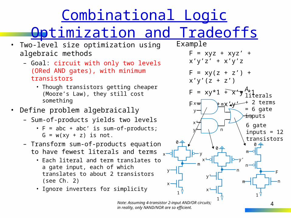
Combinational Logic Optimization and Tradeoffs• Two-level size optimization using
algebraic methods– Goal: circuit with only two levels (ORed
AND gates), with minimum transistors• Though transistors getting cheaper
(Moore’s Law), they still cost something
• Define problem algebraically– Sum-of-products yields two levels
• F = abc + abc’ is sum-of-products; G = w(xy + z) is not.
– Transform sum-of-products equation to have fewest literals and terms
• Each literal and term translates to a gate input, each of which translates to about 2 transistors (see Ch. 2)
• Ignore inverters for simplicity
F = xyz + xyz’ + x’y’z’ + x’y’z
F = xy(z + z’) + x’y’(z + z’)
F = xy*1 + x’y’*1
F = xy + x’y’
0
1
x’ y’
ny’
x’
0
1
m
m
n
n
F
0
1
y
my
x
x
F
x
y
x’
y’
m
n
4 literals + 2 terms = 6 gate inputs
6 gate inputs = 12 transistors
Note: Assuming 4-transistor 2-input AND/OR circuits;in reality, only NAND/NOR are so efficient.
Example

5
Algebraic Two-Level Size Minimization• Previous example showed common
algebraic minimization method– (Multiply out to sum-of-products, then)– Apply following as much possible
• ab + ab’ = a(b + b’) = a*1 = a
• “Combining terms to eliminate a variable”– (Formally called the “Uniting theorem”)
– Duplicating a term sometimes helps• Note that doesn’t change function
– c + d = c + d + d = c + d + d + d + d ...
– Sometimes after combining terms, can combine resulting terms
F = xyz + xyz’ + x’y’z’ + x’y’z
F = xy(z + z’) + x’y’(z + z’)
F = xy*1 + x’y’*1
F = xy + x’y’
F = x’y’z’ + x’y’z + x’yz
F = x’y’z’ + x’y’z + x’y’z + x’yz
F = x’y’(z+z’) + x’z(y’+y)
F = x’y’ + x’z
G = xy’z’ + xy’z + xyz + xyz’
G = xy’(z’+z) + xy(z+z’)
G = xy’ + xy (now do again)
G = x(y’+y)
G = x
a
a
a

6
Karnaugh Maps for Two-Level Size Minimization• Easy to miss “seeing” possible opportunities
to combine terms• Karnaugh Maps (K-maps)
– Graphical method to help us find opportunities to combine terms
– Minterms differing in one variable are adjacent in the map
– Can clearly see opportunities to combine terms – look for adjacent 1s
• For F, clearly two opportunities• Top left circle is shorthand for x’y’z’+x’y’z =
x’y’(z’+z) = x’y’(1) = x’y’• Draw circle, write term that has all the literals
except the one that changes in the circle– Circle xy, x=1 & y=1 in both cells of the circle,
but z changes (z=1 in one cell, 0 in the other)
• Minimized function: OR the final terms
F = x’y’z + xyz + xyz’ + x’y’z’
0 0
0 0
00 01 11 10
0
1
F yz
x
1
x’y’
1 1 0 0
00 01 11 10
0 0
0
1 1 1
F yz
x
xy
x’y’z’
00 01 11 10
0
1
x’y’z x’yz x’yz’
xy’z’ xy’z xyz xyz’
F yzx
1
Notice not in binary order
Treat left & right as adjacent too
1 1
F = x’y’ + xy
Easier than all that algebra:
F = xyz + xyz’ + x’y’z’ + x’y’zF = xy(z + z’) + x’y’(z + z’)F = xy*1 + x’y’*1F = xy + x’y’
K-map
a
a
a

7
K-maps• Four adjacent 1s means
two variables can be eliminated– Makes intuitive sense – those
two variables appear in all combinations, so one must be true
– Draw one big circle – shorthand for the algebraic transformations above
G = xy’z’ + xy’z + xyz + xyz’
G = x(y’z’+ y’z + yz + yz’) (must be true)
G = x(y’(z’+z) + y(z+z’))
G = x(y’+y)
G = x
0 0 0 0
00 01 11 10
1 1
0
1 1 1
G yz
x
x
0 0 0 0
00 01 11 10
1 1
0
1 1 1
G yz
x
xyxy’
Draw the biggestcircle possible, oryou’ll have more termsthan really needed

8
K-maps• Four adjacent cells can be in
shape of a square• OK to cover a 1 twice
– Just like duplicating a term• Remember, c + d = c + d + d
• No need to cover 1s more than once– Yields extra terms – not minimized
0 1 1 0
00 01 11 10
0 1
0
1 1 0
H yz
x
z
H = x’y’z + x’yz + xy’z + xyz (xy appears in all combinations)
0 1 0 0
00 01 11 10
1 1
0
1 1 1
I yz
x
x
y’z
The two circles are shorthand for:I = x’y’z + xy’z’ + xy’z + xyz + xyz’I = x’y’z + xy’z + xy’z’ + xy’z + xyz + xyz’I = (x’y’z + xy’z) + (xy’z’ + xy’z + xyz + xyz’)I = (y’z) + (x)
1 1 0 0
00 01 11 10
0 1
0
1 1 0
J yz
x
xz
y’zx’y’
a
a
a

9
K-maps• Circles can cross left/right sides
– Remember, edges are adjacent• Minterms differ in one variable only
• Circles must have 1, 2, 4, or 8 cells – 3, 5, or 7 not allowed– 3/5/7 doesn’t correspond to
algebraic transformations that combine terms to eliminate a variable
• Circling all the cells is OK– Function just equals 1
0 1 0 0
00 01 11 10
1 0
0
1 0 1
K yz
x
xz’
x’y’z
0 0 0 0
00 01 11 10
1 1
0
1 1 0
L yz
x
1 1 1 11
00 01 11 10
1 1
0
1 1 1
E yz
x

10
K-maps for Four Variables• Four-variable K-map follows
same principle– Adjacent cells differ in one
variable– Left/right adjacent– Top/bottom also adjacent
• 5 and 6 variable maps exist– But hard to use
• Two-variable maps exist– But not very useful – easy to do
algebraically by hand
0 0 1 0
00 01 11 10
1 1
00
01 1 0
0 0 1 0
0 0
11
10 1 0
F yz
wx
yz
w’x
y’
0 1 1 0
00 01 11 10
0 1
00
01 1 0
0 1 1 0
0 1
11
10 1 0
G yz
wx
z
0 1
0
1
F z
y
G=z
F=w’xy’+yz

11
Two-Level Size Minimization Using K-mapsGeneral K-map method
1. Convert the function’s equation into sum-of-products form
2. Place 1s in the appropriate K-map cells for each term
3. Cover all 1s by drawing the fewest largest circles, with every 1 included at least once; write the corresponding term for each circle
4. OR all the resulting terms to create the minimized function.
Example: Minimize:
G = a + a’b’c’ + b*(c’ + bc’)
1. Convert to sum-of-products
G = a + a’b’c’ + bc’ + bc’
2. Place 1s in appropriate cells
0 0
00 01 11 10
0
1
G bc
a
1
bc’
1a’b’c’1 1 1 1
a
a
3. Cover 1s
1 0 0 1
00 01 11 10
1 1
0
1 1 1
G bc
a
a
c’
4. OR terms: G = a + c’

12
• Minimize:– H = a’b’(cd’ + c’d’) + ab’c’d’ + ab’cd’
+ a’bd + a’bcd’
1. Convert to sum-of-products:– H = a’b’cd’ + a’b’c’d’ + ab’c’d’ +
ab’cd’ + a’bd + a’bcd’
2. Place 1s in K-map cells
3. Cover 1s
4. OR resulting terms
Two-Level Size Minimization Using K-maps – Four Variable Example
1 1
00 01 11 10
00
01 1 1 1
1
11
10
0 0
0
0 0 0 0
0 0 1
H cd
ab
a
a’bd
a’bc
b’d’
Funny-looking circle, but remember that left/rightadjacent, and top/bottom adjacent
a’b’c’d’
ab’c’d’ a’bda’b’cd’
ab’cd’
a’bcd’
H = b’d’ + a’bc + a’bd

13
Multi-Level Logic Optimization – Performance/Size Tradeoffs
• We don’t always need the speed of two level logic– Multiple levels may yield fewer gates– Example
• F1 = ab + acd + ace F2 = ab + ac(d + e) = a(b + c(d + e))• General technique: Factor out literals – xy + xz = x(y+z)
ace
ca
a
b
d
4F1
F2
F1 = ab + acd + ace(a)
F2 = a(b+c(d+e))(b) (c)
22 transistors2 gate delays
16 transistors4 gate-delays
a
b
c
d
e
F1
F220
15
10
5
1 2 3 4delay (gate-delays)
4
4
4
4
4
6
6
6
size
(tra
nsi
stors
)

14
Multi-Level Example
• Q: Use multiple levels to reduce number of transistors for– F1 = abcd + abcef
a
• A: abcd + abcef = abc(d + ef)• Has fewer gate inputs, thus fewer transistors
abcef
bc
a
dF1
F2
F1 = abcd + abcef F2 = abc(d + ef)(a) (b) (c)
22 transistors2 gate delays
18 transistors3 gate delays
abc
d
e
f
F1
F220
15
10
5
1 2 3 4delay (gate-delays)
46
4
4
8
10
4
size
(tra
nsi
stors
)

15
State Reduction (State Minimization)
x y
if x = 1,1,0,0then y = 0,1,1,0,0
• Goal: Reduce number of states in FSM without changing behavior– Fewer states potentially reduces size of state register
• Consider the two FSMs below with x=1, then 1, then 0, 0
xstate
y
xstate
y
S0 S0S1 S1S1 S1S2 S0S2 S0
S0 S1
y=0 y=1
S2
y=0
S3
y=1
x
x x
x’
x’
xx’ x’
Inputs: x; Outputs: y
S0 S1
y=0 y=1
x’ x
x
x’
For the same sequence of inputs,the output of the two FSMs is the same
a

16
State Reduction: Equivalent StatesTwo states are equivalent if:
1. They assign the same values to outputs– e.g. S0 and S2 both assign y to 0,– S1 and S3 both assign y to 1
2. AND, for all possible sequences of inputs, the FSM outputs will be the same starting from either state– e.g. say x=1,1,0,0,…
• starting from S1, y=1,1,0,0,…
• starting from S3, y=1,1,0,0,…
S0 S1
y=0 y=1
S2
y=0
S3
y=1
x
x x
x’
x’
xx’ x’
Inputs: x; Outputs: y
States S0 and S2 equivalent
States S1 and S3 equivalent
S0,S2
S1,S3
y=0 y=1
x’ x
x
x’
a
17
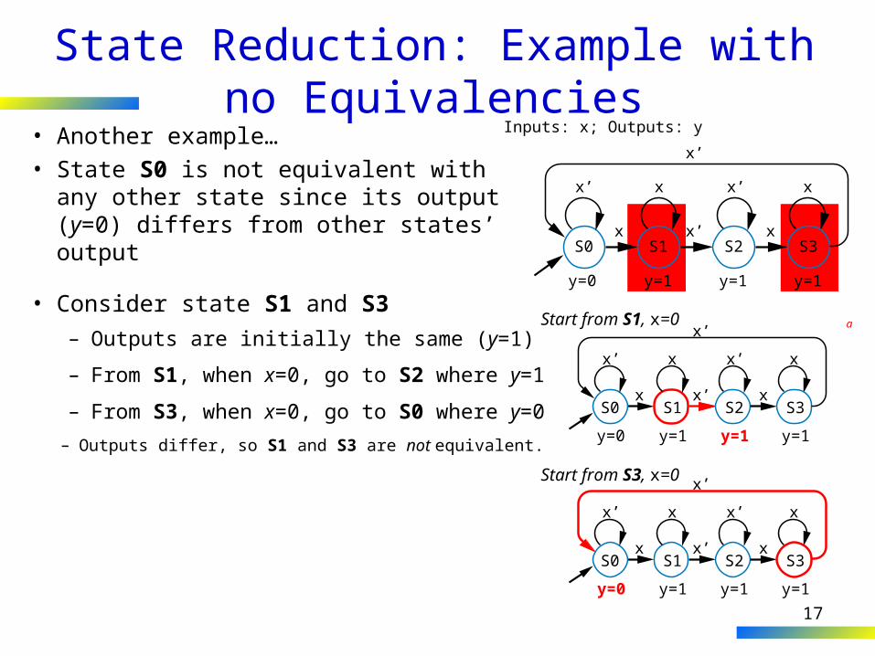
State Reduction: Example with no Equivalencies• Another example…• State S0 is not equivalent with any
other state since its output (y=0) differs from other states’ output S1
y=0 y=1
S2
y=1
S3
y=1
x x
x x
x’
x’
x’
x’
Inputs: x; Outputs: y
S0
• Consider state S1 and S3
S1
y=0 y=1
S2
y=1
S3
y=1
x x
x x
x’
x’
x’
x’
S0
Start from S1, x=0
S1
y=0 y=1
S2
y=1
S3
y=1
x x
x x
x’
x’
x’
x’
S0
Start from S3, x=0
– Outputs are initially the same (y=1)
– From S1, when x=0, go to S2 where y=1
– From S3, when x=0, go to S0 where y=0– Outputs differ, so S1 and S3 are not equivalent.
a

18
State Encoding• Encoding: Assigning a unique
bit representation to each state• Different encodings may
optimize size, or tradeoff size and performance
• Consider 3-Cycle Laser Timer…– Example 3.7’s encoding: 15
gate inputs
– Try alternative encoding• x = s1 + s0• n1 = s0• n0 = s1’b + s1’s0• Only 8 gate inputs
11 10
00
01 10 11
b’
b
x=0
x=1 x=1 x=1
Inputs: b; Outputs: x
On1 On2 On3
Off
11
00
11
00
a

19
State Encoding: One-Hot Encoding• One-hot encoding
– One bit per state – a bit being ‘1’ corresponds to a particular state
– Alternative to minimum bit-width encoding in previous example
– For A, B, C, D: A: 0001, B: 0010, C: 0100, D: 1000
• Example: FSM that outputs 0, 1, 1, 1– Equations if one-hot encoding:
• n3 = s2; n2 = s1; n1 = s0; x = s3 + s2 + s1
– Fewer gates and only one level of logic – less delay than two levels, so faster clock frequency
00
01
Inputs: none; Outputs: xx=0
x=1
A
B
11
10
D
C
x=1
x=1
1000
0100
0001
0010
clk
s1
n1
x
s0n0
State registerclk
n0
s3 s2 s1 s0
n1n2
n3
State register
x
8642
2 3 41delay (gate-delays)
one-hot
binary
a

20
One-Hot Encoding Example: Three-Cycles-High Laser Timer
• Four states – Use four-bit one-hot encoding– State table leads to equations:
• x = s3 + s2 + s1• n3 = s2• n2 = s1• n1 = s0*b• n0 = s0*b’ + s3
– Smaller• 3+0+0+2+(2+2) = 9 gate inputs• Earlier binary encoding (Ch 3): 15
gate inputs
– Faster • Critical path: n0 = s0*b’ + s3• Previously: n0 = s1’s0’b + s1s0’• 2-input AND slightly faster than 3-
input AND
0001
0010 0100 1000
b’
b
x=0
x=1 x=1 x=1
Inputs: b; Outputs: x
On1 On2 On3
Off
a