1 ngao sdr agenda 9:00 welcome & introductions (armandroff) 9:10 charge (lewis) 9:20 review...
Post on 20-Dec-2015
213 views
TRANSCRIPT

1
NGAO SDR Agenda
9:00 Welcome & Introductions (Armandroff)
9:10 Charge (Lewis)
9:20 Review Panel closed session (Hubin)
9:45 Re-entry for non-Panel participants
9:50 Comments from Chair (Hubin)
10:00 NGAO Report
17:30 General Discussion & Questions (Hubin et al.)
18:00 End
KAON 584: NGAO SDR Presentation

2
LGSAO Kuiper Belt objects
Galactic Center
Merging galaxies Substellar binaries
Crab Nebula
Keck AO has been a tremendous success thus far

3
AO Science Productivity
• 175 refereed AO science papers – 38 LGS AO– 18 Interferometer
Refereed Keck AO Science Papers by Year & Type
0.0
5.0
10.0
15.0
20.0
25.0
2000 2001 2002 2003 2004 2005 2006 2007
Year
Nu
mb
er o
f P
aper
s
Solar System
Galactic
Extra-galactic
Refereed Keck AO Science Papers by Year & Type
0
5
10
15
20
25
30
2000 2001 2002 2003 2004 2005 2006 2007
Year
Nu
mb
er o
f P
aper
s
IF
LGS
NGS

4
Most recent AO upgrade, NGWFC, resulted in significant performance gains
60+% Strehl for R=14 NGS
Natural Guide Star
Laser Guide Star

5
WMKO is committed to raisingneeded NGAO funds
• Funding plans will be reviewed by CARA Board• Goodwin, Armandroff, Bolte & Kulkarni are
charged with NGAO fundraising• 2/3 private support
– Very active Advancement Office at WMKO– MOSFIRE: about 50% private support
• 1/3 federal support– All relevant funding opportunities– ExoPlanet Task Force recommendation: “Implement next-
generation high spatial resolution imaging techniques on ground-based telescopes (AO for direct detection of young low mass companions)”

6
Welcome Attendees
Reviewers: Norbert Hubin (Chair - ESO), Brent Ellerbroek (TMT), Bob Fugate (NMT), Andrea Ghez (UCLA), Gary Sanders (TMT), Nick Scoville (CIT)
SSC: Jean Brodie (UCSC), Tom Greene (NASA), Mike Liu (UH), Chris Martin (CIT), Jerry Nelson (UCSC)
TSIP: Robert Blum, Mark Trueblood
Directors: Taft Armandroff (WMKO), Hilton Lewis (WMKO), Shri Kulkarni (CIT)
NGAO Participants:
CIT: Antonin Bouchez, Rich Dekany, Anna Moore, Viswa Velur
UCSC: Don Gavel, Renate Kupke, Chris Lockwood, Claire Max, Liz McGrath, Marco Reinig
WMKO: Sean Adkins, Erik Johansson, David Le Mignant, Chris Neyman, Peter Wizinowich

Thank you for Thank you for your role in your role in
making Keck making Keck NGAO a success!NGAO a success!

8
Review Panel Report Questions
1. Assess the impact of the science cases in terms of the competitive landscape in which the system will be deployed.
2. Assess the maturity of the science cases & science requirements and the completeness & consistency of the technical requirements.
3. Evaluate the conceptual design for technical feasibility & risk, & assess how well it meets the scientific & technical requirements.
4. Assess whether the design can be implemented within the proposed schedule & budget.
5. Evaluate the suitability & effectiveness of the project management, organization, decision making & risk mitigation approaches, with an emphasis on the next project phase (preliminary design) and also with respect to the entire project.
6. Provide feedback on whether the overall strategy will optimize the delivery of new science.
7. Gauge the readiness of the project to proceed to the preliminary design phase.

9
NGAO SDR Agenda
9:00 Welcome & Introductions (Armandroff)
9:10 Charge (Lewis)
9:20 Review Panel closed session (Hubin)
9:45 Re-entry for non-Panel participants
9:50 Comments from Chair (Hubin)
10:00 NGAO Report
17:30 General Discussion & Questions (Hubin et al.)
18:00 End

NGAO System Design Review NGAO System Design Review ReportReport
Peter Wizinowich, Rich Dekany, Don Gavel, Claire MaxPeter Wizinowich, Rich Dekany, Don Gavel, Claire Maxfor NGAO Team:for NGAO Team: S. Adkins, B. Bauman, A. Bouchez, M. Britton, S. Adkins, B. Bauman, A. Bouchez, M. Britton,
J. Bell, J. Chin, R. Flicker, E. Johansson, R. Kupke, D. Le Mignant, J. Bell, J. Chin, R. Flicker, E. Johansson, R. Kupke, D. Le Mignant, C. Lockwood, E. McGrath, D. Medeiros, A. Moore, C. Lockwood, E. McGrath, D. Medeiros, A. Moore,
C. Neyman, M. Reinig, V. VelurC. Neyman, M. Reinig, V. Velur
System Design ReviewSystem Design ReviewApril 21, 2008April 21, 2008

11
NGAO SDR Agenda10:00 Introduction & Presentation Approach (Wizinowich)10:05 Science Cases & Science Requirements (Max) SCRD11:15 Break11:30 Requirements (Wizinowich) SRD,FRD12:00 Design (Gavel) SDM12:30 Lunch13:30 Design Q&A (Gavel) SDM14:00 Performance Budgets (Dekany) SDM14:45 Project Management (Wizinowich) SEMP15:15 Risks (Wizinowich) Risk
KAONs15:45 Break16:00 Cost Estimate (Dekany) SEMP16:40 PD Schedule & Budget (Wizinowich) SEMP
+ Phased Implementation17:20 Conclusion (Wizinowich)17:30 General Discussion & Questions (Hubin et al.)18:00 End

12
Tomorrow’s Agenda
8:30 Review Panel closed session (Hubin)
9:30 Questions for NGAO EC as needed
10:00 Review Panel closed session
11:30 Review Panel draft report (Hubin)To Directors & NGAO EC
12:15 Lunch
13:00 End

13
Presentation Approach
• The agenda topics were selected to correspond to the major System Design deliverables and the 7 topics in the Review Panel Charge.– With input from the Panel Chair.
• Each session in the agenda is organized to:– Provide a brief overview to address the specific charge & associated
questions.
– Provide answers to major questions from the reviewers.
– Provide time for additional reviewer questions & team responses.
• Assumptions: – People have read the System Design materials.
– Reviewers have read our responses to their questions.• 89 questions received & answered.
– We will not need to use this meeting to bring people up to speed.

Science Case & Science Case & Science Case Requirements Science Case Requirements

15
Charges 1 & 2: Science CasesCharges 1 & 2: Science Cases• Charge 1: “Assess the impact of the science cases in
terms of the competitive landscape in which the system will be deployed.”– “Are the science cases given in the Science Case Requirements
document complete & compelling?”
• Charge 2: “Assess the maturity of the science cases & science requirements ...”– “Are the science requirements clear, complete & compelling?”
• NGAO Team response: – NGAO will provide the WMKO community with an extremely
competitive & complementary facility.– The science cases addressed to date are complete and
compelling, and the science requirements are well defined.• Some requirements will be further developed during PD.

16
We categorized science cases into 2 classesWe categorized science cases into 2 classes
1.1. Key Science Drivers:Key Science Drivers:
– These push the limits of AO system, instrument, and telescope performance. Determine the most difficult performance requirements.
2.2. Science Drivers:Science Drivers:
– These are less technically demanding but still place important requirements on available observing modes, instruments, and PSF knowledge.

17
““Key Science Drivers” Key Science Drivers” (in inverse order of distance)(in inverse order of distance)
1.1. High-redshift galaxiesHigh-redshift galaxies
2.2. Black hole masses in nearby AGNsBlack hole masses in nearby AGNs
3.3. General Relativity at the Galactic CenterGeneral Relativity at the Galactic Center
4.4. Planets around low-mass starsPlanets around low-mass stars
5.5. Asteroid companionsAsteroid companions

18
1.1. Gravitationally lensed galaxiesGravitationally lensed galaxies
2.2. QSO host galaxiesQSO host galaxies
3.3. Resolved stellar populations in crowded fieldsResolved stellar populations in crowded fields
4.4. Astrometry science (variety of cases)Astrometry science (variety of cases)
5.5. Debris Disks and Young Stellar ObjectsDebris Disks and Young Stellar Objects
6.6. Giant Planets and their moonsGiant Planets and their moons
7.7. Asteroid size, shape, compositionAsteroid size, shape, composition
““Science Drivers” Science Drivers” (in inverse order of distance)(in inverse order of distance)

19
Conclusions from Science CasesConclusions from Science Cases
• Our scientists want a high performance AO system that will enable a wide variety of science cases
• They want it to open up new vistas of both wide and narrow field science at shorter wavelengths andand higher sky coverage
• We determined that these science goals could best be met by using new technologies rather than modest extension of existing ones– Scaling existing technologies did not meet the desired science
performance (KAON 461)
– Any new Keck AO system will be expensive, and hence should have a commensurately large payoff
• Keck has an excellent history of world leadership in AO– First high-order AO systems on 8-10 m telescopes
– First operational laser guide star
• High payoff at modest risk are consistent with Keck’s approach to science and instrumentation

20
Charge 1: “Assess impact of science cases in Charge 1: “Assess impact of science cases in terms of competitive landscape...”terms of competitive landscape...”
• Other ground-based observatories
• JWST & ALMA
• TMT

21
NGAO in the world of 8-10 m telescopes: NGAO in the world of 8-10 m telescopes: Uniqueness is high spatial resolution, shorter Uniqueness is high spatial resolution, shorter ’s, AO-fed NIR d-IFS’s, AO-fed NIR d-IFS
• Most 8-10 m telescopes plan either high contrast or wide field AO
• Only the VLT has a narrow-field mode (7.5” FOV, 10% Strehl @ 750 nm)
Type Telescope GSNext-Generation AO Systems
for 8 to 10 m telescopesCapabilities Dates
High-contrast Subaru N/LGS Coronagraphic Imager Hi(CIAO)Good Strehl, 188-act curvature,
4W laser2008
High-contrast VLT NGS Sphere (VLT-Planet Finder) High Strehl 2010
High-contrast Gemini-S NGS Gemini Planet Imager (GPI) Very high Strehl 2010
Wide-field Gemini-S 5 LGS MCAO 2Õ FOV 2009
Wide-field Gemini 4 LGS GLAO Feasibility Study Completed ?
Wide-field VLT 4 LGSHAWK-I (near IR imager) +
GRAAL GLAO7.5' FOV, AO seeing reducer,
2 x EE in 0.1''2012
Wide-field VLT 4 LGSMUSE (24 vis. IFUs) +
GALACSI GLAO1' FOV; 2 x EE in 0.2" at 750nm 2012
Narrow-field VLT 4 LGSMUSE (24 vis. IFUs) +
GALACSI GLAO7.5Ó FOV, 10% Strehl @ 750 nm 2012
Table 1. Next-Generation AO Systems Under Development for 8 - 10 meter Telescopes

22
JWST will push major advances in:JWST will push major advances in:
• End of the Dark AgesEnd of the Dark Ages
• Assembly of galaxiesAssembly of galaxies
• Birth of stars, protoplanetary systemsBirth of stars, protoplanetary systems
• Properties of planetary systems including our ownProperties of planetary systems including our own
Our goal is to position NGAO to build on, and complement, JWST discoveries
Our goal is to position NGAO to build on, and complement, JWST discoveries

23
Competitive Landscape: JWSTCompetitive Landscape: JWST
• JWST advantages– JWST will have better sensitivity than NGAO (low
backgrounds)– Diffraction limited imaging between 2.4 and 5 m – Multiplexed slit spectroscopy (x 100)
• But only 1 IFU
– Maximum spectral resolution R = 2700
• Keck NGAO advantages– Better spatial resolution than JWST at
wavelengths below 2 m• JWST pixels under-sample the diffraction limit at
these wavelengths
– Spectroscopy at spatial resolutions < 0.1”– Multi-IFU spectroscopy– Spectroscopy at spectral resolutions R > 2700– Higher resolution imaging at wavelengths < 2 m

24
Competitive Landscape: ALMACompetitive Landscape: ALMA
• Millimeter and sub-millimeter wavelengths (0.35 - 9 mm)
• Typical spatial resolutions ~ 0.1”
• Resolutions for widest arrays as low as 0.004” at the highest frequencies
• ALMA science: regions colder and more dense than those seen in the visible and near-IR by NGAO
• Keck NGAO observations of H2 and atomic hydrogen near IR emission lines: characterize warmer outer regions of the disks and molecular clouds seen by ALMA, at similar spatial resolution
• Keck NGAO and ALMA observations complementary for:
– Spatially resolved galaxy kinematics, z < 3
– Debris disks and young stellar objects

25
Complementarity with TMTComplementarity with TMT
• TMT (2017?)
– TMT has significant spatial resolution & sensitivity advantages over NGAO
– NGAO d-IFS has spatially resolved spectra & higher spatial resolution than TMT’s IRMS; available a generation before IRMOS
– NGAO proving MOAO, variable asterisms, Point-and-Shoot sharpening, MEMS DM’s, to TMT’s benefit

26
NGAO with multiplexed IFU: NGAO with multiplexed IFU: a real complement to TMTa real complement to TMT
• TMT IRMS: AO multi-slit (MOSFIRE) fed by MCAO– Slits: 0.12” and 0.16”, Field of regard: 2 arc min– Lower backgrounds: 10% of sky + telescope
• NGAO with multiplexed deployable IFUs– MOAO better spatial resolution than MCAO over full field– Better spatial resolution: 0.07” is current spec.– Higher backgrounds: 30% of sky + telescope (but much better
than current AO system)
• TMT IRMS strengths: lower backgrounds, higher sensitivity• NGAO d-IFU strengths: higher spatial resolution, 3D information,
wide field performance• NGAO d-IFU a pathfinder for TMT IRMOS
• TMT IRMS strengths: lower backgrounds, higher sensitivity• NGAO d-IFU strengths: higher spatial resolution, 3D information,
wide field performance• NGAO d-IFU a pathfinder for TMT IRMOS

27
Charge 2: “Assess the maturity of the science Charge 2: “Assess the maturity of the science cases & science requirements ...”cases & science requirements ...”
• Science Cases fully described in the Science Case Requirements Document (SCRD, KAON 455)
• Here: Choose one “Key Science Driver” and walk through the requirements process with you
Galaxy Assembly and Star Formation HistoryGalaxy Assembly and Star Formation History
• Broad scientific goals• Major sub-cases• How requirements were derived• Remaining issues

28
Galaxy Assembly and Star Formation History: Galaxy Assembly and Star Formation History: Focusing our AnalysisFocusing our Analysis
• “High Redshift Galaxies” has very wide scope– z > 6: Finding and characterizing galaxies
– 3 < z < 6: Morphologies, colors
– 1 < z < 3: Internal kinematics, structure at time of peak star formation
• To define “Key Science Driver” we focused on 1 < z < 3– 1 < z < 3 epoch: spatial resolution of 10-m telescope has strong impact
• Prominent emission lines redshifted to J, H, K bands
• Sufficient signal-to-noise to spatially resolve internal kinematics, star formation rates, metallicity gradients using spatially resolved spectroscopy
StarFormation
High Redshift Galaxy
Bulge
Spiral Arm
Super- nova
star cluster
Internal velocities
Metallicity
JWST will JWST will excel hereexcel here

29
What is happening to galaxies at 1 z 3?• At z ~ 1 – 3, galaxies accumulate most of their stellar
mass, rate of major mergers peaks.
• This activity transforms irregular galaxies into the familiar Hubble sequence of the local universe.
• Studying these galaxies in detail is key to understanding galaxy formation and the buildup of structure in the universe.
– Global properties of these galaxies are being well studied.
– Little is known about internal kinematics or small-scale structure, mode of dynamical support, spatial distribution of star formation.
– Is star formation due to rapid nuclear starbursts during major mergers? To circum-nuclear starbursts caused by bar-mode or other gravitational instabilities? Or to consumption of gas reservoirs in stable rotationally-supported structures?

30
Substantial benefit from observing many of these galaxies at once
• In survey mode, could make good use of as many as 20-25 IFUs at once
• In more focused mode, typical science paper will study a sub-category of these galaxies. Multiplexing factors of 6-12 fit many subcases.
Type of Object Density per sq arc min
SCUBA sub-mm galaxies to 8 mJy 0.1
Old and red galaxies with 0.85 < z < 2.5 and R < 24.5
2
Field galaxies w/ emission lines in JHK windows, 0.8 < z < 2.6 & R < 25
> 25
Center of rich cluster of galaxies at z > 0.8 > 20
All galaxies K < 23 > 40

31
Many Sub-Cases, Galaxies at 1 Many Sub-Cases, Galaxies at 1 z z 3 3
• Kinematic evolution from random sub-pieces to organized rotation
• Patterns of star formation (nuclear first? rings? uniform? ...) and their trends with redshift
• Dependence of star formation rate on current merger activity and/or existence of close companion galaxies
• How does status as Active Galactic Nucleus influence star formation pattern and rate?
• Does status as Active Galactic Nucleus correlate with recent merger activity? Existence of close companion galaxies?
• Sub-classes of targets will be selected using ongoing large surveys (e.g. COSMOS, GOODS, ...)
Goal is to derive science requirements to jointly optimize as many of these sub-cases as possibleGoal is to derive science requirements to jointly optimize as many of these sub-cases as possible

32
Requirements Shared by Most Sub-CasesRequirements Shared by Most Sub-Cases
• Spatially resolved spectroscopy (2 spatial dimensions)
– e.g. to distinguish ordered rotation from discrete sub pieces, to see patterns of star formation or metallicity
– Size of field for each galaxy? “Typical” galaxy is 1 arc sec; want additional real estate in order to measure sky background or to accomodate larger galaxies when needed. Chose 1” x 3” as minimum field size for IFUs.
• High sky coverage fraction: ≥ 30%
• Multiplexing to maximize science return per hour of observing
– Multiplexing factor of N is equivalent to N Keck Telescopes
– Requirement: Target sample size of ≥ 200 galaxies observable with ~10 nights of allocated telescope time. (More on next slide)
• Spectral bands: J, H, K with spectral resolution 3000-4000
– Major emission lines redshifted into JHK (H and [NII], [OII], [OIII])
– Spectral resolution chosen to look between the OH night-sky lines
• Choose lowest resolution that does this, to preserve faint-object sensitivity

33
Sensitivity Requirement is the Hardest to Jointly Optimize
• Overall requirement: spectra of ≥ 200 high-z galaxies in 10 nights of observing time
Must be able to observe ≥ 20 galaxies per 10-hour night (see table) to SNR ≥ 10
• Choice of pixel / spaxel scale is key, for galaxies with at least some fuzzy structure
– Extended H emission, low surface-brightness disks, largest galaxies, ...
– For these, larger pixels/spaxels are better for SNR. Optimum at 0.1”/px or more.
– But of course larger pixels/spaxels are worse for spatial resolution
• For smaller galaxies at 1 z 3, or those that have point-like substructures, pixel scales 0.05” are best * Not desirable
Integration time to reach SNR ≥ 10
implies this
minimum IFU
Multiplicity
0.5 hrs 1
1 hr 2
2 hrs 4
3 hrs 6
6 hrs* 12
10 hrs* 20

34
Sensitivity Requirement and Pixel/Spaxel Size, continued
• Recap: – Sensitivity will depend on pixel/spaxel size
– Different sub-cases of the 1 ≤ z ≤ 3 science case optimize at different pixel/spaxel sizes
– Large galaxies with diffuse Ha emission: 0.1” / px or more
– “Galaxies” consisting of several point-like star-forming knots: ≤ 0.05”
• Compromise for the deployable IFU: pixel/spaxel scale = 0.07”– Narrow-field high-resolution IFU (OSIRIS-like) will have variable scales.
For example OSIRIS goes down to 0.02”
• Implications for the deployable IFU:
– Can meet 200-galaxy requirement with 0.07” spaxels, background due to AO less than 30% of unattenuated (sky + telescope) between OH lines
– Yields 2-3 hr integration times (see next slide), min 4-6 deployable IFUs

35
Requirement on AO background: Requirement on AO background: Example of analysis logicExample of analysis logic
• Tint = 3 hours AO contribution to background = 30%, 6 IFUs
• Then 70% throughput cool AO system to -15C
• Calculations will be refined for PDR, now that optical design is defined

36
Each Science Driver has a “Requirements Table”
• Summarizes requirements discussed in text and figures
• Formatted for input into System Requirements Document and into the Contour Database of Functional Requirements
• Example: part of the Requirements Table for High-Redshift Galaxies
Requirements Table 1. High-Redshift Galaxies derived requirements
# Science Performance Requirement
AO Derived Requirements
Instrument Requirements
1.1 Spectral Sensitivity. SNR 10 for a z = 2.6 galaxy in an integration time Š 3 hours for a spectral resolution R = 3500 with a spatial resolution of 50 mas
Sufficiently high throughput and low emissivity of the AO system science path to achieve this sensitivity. Background due to AO less than 30% of unattenuated (sky + telescope) at wavelength of 2209 nm and at a spectral resolution / = 5000.
1.2 Target sample size of 200 galaxies in Š 3 years (assuming a target density of 4 galaxies per square arcmin)
Multi-object AO system: one DM per arm, or an upstream MCAO system correcting the entir e field of regard. 6-12 arms on 5 square arc minutes patrol field.
Multiple (6-12) IFUs, deployable on the 5 square arc minute field of regard
1.3 Spectroscopic and imaging observing wavelengths = J, H and K (to 2.4 µm)
AO system must transmit J, H, and K bands1
Infrared imager and IFUs designed for J, H, and K. Each entire wavelength band should be observable in one exposure.
1.4 Spectral resolution = 3000 to 4000
Spectral resolution of >3000 in IFUs
1.5 Narrow field imaging: diffraction limited at J, H, K
Wavefront error 170 n m or better
Nyquist sampled pixels a t each wavelength
1.6 Encircled energy at least 50% in 70 mas for sky coverage of 30% (see 1.12)
Wavefront err or sufficiently low (~170 nm) to achieve the stated requirement in J, H, and K bands.
IFU spaxel size: either 3 5 or 70 mas, TBD during the design study for th e multiplexed IFU spectrograph
1.7 Velocity determined to Š 20 km/sec for spatial resolutions of 70 mas
PSF intensity distributio n known to Š 10 % per spectral channel.
1.8 IFU field of view 1” x 3” to allow sky background meas’t at same time as observing a ~1” galaxy
Each MOAO IFU channel passes a 1”x3” field.
Each IFU unit’s field o f view is 1” x 3”

37
Science Team Tasks During PD Phase
• Expand upon goals of “Science Drivers”, and finish documenting the AO performance necessary to achieve these goals.
• Generate a Science Requirements Summary Matrix that rolls-up the most demanding requirements for each part of the architecture
• Develop detailed observing scenarios for each “Key Science Driver” to define pre- and post-observing tools and observing sequences.
• Detailed science simulations of “Key Science Drivers” to assess the required level of PSF accuracy, stability, uniformity, and knowledge as a function of position and time. Implications for:
– achievable astrometric and photometric accuracy
– achievable contrast ratio
– morphological studies

38
Science Team Tasks During DD-FSD Phases
• Develop a “Design Reference Mission” for at least two “Key Science Drivers”
– Simulate expected on-sky performance.
– End-to-end simulation: planning tools, observing proposal, observing sequences, science operations, PSF models, analysis tools, data products.
– Integrate tasks and deliverables from throughout the NGAO Work Breakdown Structure to ensure they work together and provide a seamless observing process that meets all specifications.
• Design Reference Mission will help ensure that commissioning runs smoothly, to advance to full-scale science operations as quickly as possible and maximize the scientific return of NGAO.

39
Additional Science Team Efforts
• Continued discussions with Keck community to ensure that science case requirements remain consistent and up-to-date with changing methodology, advancing AO system design, and maturing instrument concepts.
• Input from observers to improve planning tools, observing practices, support, and efficiency.
• Feedback regarding NGAO science opportunities that complement other ground-based AO and space-based facilities, and that take advantage of the uniqueness space provided by NGAO at Keck.

40
Reviewer Q & A
• MCAO/MOAO Trade-offs
• Contrast requirements and capabilities
• PSF requirements and analyses

41
MCAO/MOAO Tradeoff: Key Science Drivers
• Four of the five Key Science Drivers use very narrow fields:
– Black hole mass in nearby AGNs ( 5 arc sec field)
– General Relativity in the Galactic Center (10 arc sec field)
– Extrasolar planets around nearby stars (5 arc sec field)
– Minor planet multiplicity (3 arc sec field)
The fifth Key Science Driver, Galaxy Assembly and Star Formation History, needs wide fields and high sky coverage.
In all Science Cases, infrared tip-tilt stars need to be AO-corrected, for high sky coverage.

42
All narrow-field Key Science Drivers are within one isoplanatic angle
• Nearby AGNs, extrasolar planets, multiplicity of minor planets use 0.85 1.6 m, field radii 3 arc sec
• Galactic Center uses ~ 2.2 m, field radius 5 arc sec
Seeing: Challenging Median Good Excellent
r0
0.5 m14 cm 16 cm 18 cm 22 cm
0
0.85 m
1.2 m
1.6 m
2.2 m
4.1”
6.2”
8.7”
12.7”
5.1”
7.7”
11.3”
16”
5.5”
8.3”
11.7”
17.2”
7.6”
11.4”
16.2”
23.7”
These cases don’t need MCAO or MOAO for the science field
These cases don’t need MCAO or MOAO for the science field

43
But most narrow field science cases need MCAO or MOAO for high sky coverage
• Laser tomography needs 3 natural stars for tip-tilt and other low modes
• For high sky coverage, these tip-tilt stars must be AO-corrected (can use fainter stars which are more plentiful)
• Drives towards infrared tip-tilt stars, since these will have better AO-correction than visible ones
• For AO correction of widely spaced tip-tilt stars, must have laser asterism extending to relatively large radius
– TMT NFIRAOS: 2 arc min technical field for tip-tilt sensors, lasers on 1.2 arc min diameter circle.
– NGAO: 2.5 arc min technical field for tip-tilt sensors; point 3 lasers directly at tip-tilt stars; science lasers variable up to 2.5 arc min diameter field.
• Can be done either using overall wide-field MCAO correction, or putting MOAO units within each tip-tilt sensor.
– This decision is independent of whether science field uses MCAO or MOAO.

44
Science Drivers (not “Key”): Which ones need wide science field?
• Narrow Field Science (< isoplanatic angle, don’t need MOAO or MCAO except for tip-tilt)
– QSO Host Galaxies– Gravitational lensing of galaxies by galaxies– Some of the narrow-field astrometry science– Debris disks– Young Stellar Objects– Size, shape, composition of minor planets– Gas giant planet moons– Uranus and Neptune
• Wider Field Science– Gravitational lensing by clusters– Some wide-field astrometry science cases– Resolved stellar populations in crowded fields– Imaging of Jupiter and Saturn disks and rings– Imaging of Uranus and Neptune rings
Can be done by mosaicing
smaller fields

45
Science Drivers (not “Key”): Which ones need wide science field?
• Narrow Field Science (< isoplanatic angle, don’t need MOAO or MCAO except for tip-tilt)
– QSO Host Galaxies– Gravitational lensing of galaxies by galaxies– Some of the narrow-field astrometry science– Debris disks– Young Stellar Objects– Size, shape, composition of minor planets– Gas giant planet moons– Uranus and Neptune
• Wider Field Science– Gravitational lensing by clusters– Some wide-field astrometry science cases– Resolved stellar populations in crowded fields– Imaging of Jupiter and Saturn disks and rings– Imaging of Uranus and Neptune rings
Potentially benefits most from MCAO

46
Can NGAO meet its contrast goals?Can NGAO meet its contrast goals?
• Science Case: Planets around
nearby low-mass stars
Brown dwarf 1/30 mass of Sun (hidden behind occulting mask)
Giant planet (2x mass of Jupiter)
Simulations by Bruce Macintosh and Chris Neyman

47
Can NGAO meet its Contrast Goals?Can NGAO meet its Contrast Goals?
Target Sample 1: Old field brown dwarfs to 20pc
Requirement: H=14, H=10 at 0.2” (2MJ at 4 AU)
Target Sample 2: Young (<100Myr) brown dwarfs & low-mass stars to 80pc
Requirement: J=11, 1MJ: J=11, 2MJ: J=8.5• (minimum) J=8.5 at 0.1”• (nominal) J=11 at 0.2”• (goal) J=11 at 0.1”
Target Sample 3: Solar-type stars in Taurus and Ophiuchus, and young clusters at 100-150 pc.
Requirement: J=10-12, 1MJ: J=13.5, 5MJ: J=9• (difficult goal) J=13.5 at 0.07”• (goal) J=9 at 0.07”

48
Simulations of Contrast Performance• Numerical simulation
inputs:– Keck pupil– 7 layer turbulence
model, median to good conditions
– 36x36 subaps– Measurement
errors due to spot elongation & fratricide
– 1 kHz frame rate– 5 LGS at 11”– Tip/Tilt error (3
NGS, J=16 at 30”)– Static telescope
errors - 65 nm
• No treatment of non-common-path errors yet
NGAO, no coronagraph
Coronagraphs
Occulting spot sizes

49
Target Sample 1
Target Sample 2a
Target Sample 2b
Target Sample 2c
Target Sample 3b
Target Sample 3a

50
Conclude that Science “Requirements” (but only one “Goal”) can be met for Exoplanets science case
Target Sample 1: Old field brown dwarfs to 20pc at 8 Requirement: H=14, H=10 at 0.2” (2MJ at 4 AU)
Target Sample 2: Young (<100Myr) brown dwarfs and low-mass stars to 80pc
Requirement: J=11, 1MJ: J=11, 2MJ: J=8.5
• (minimum) J=8.5 at 0.1” at 8 • (nominal) J=11 at 0.2” at 5 • (goal) J=11 at 0.1”
Target Sample 3: Solar-type stars in Taurus and Ophiuchus, and young clusters at 100-150 pc.
Requirement: J=10-12, 1MJ: J=13.5, 5MJ: J=9
• (difficult goal) J=13.5 at 0.07” • (goal) J=9 at 0.07” ? at 5

51
What are the requirements for What are the requirements for PSF stability and knowledge?PSF stability and knowledge?
• In System Design phase, we stated requirements in terms of photometric and astrometric accuracy
• These in turn will be only achievable with specific levels of PSF stability, uniformity, and knowledge
– “Stability” refers to temporal uniformity
– “Uniformity” refers to spatial uniformity (specify over what field)
– “Knowledge” -- no matter what the actual stability and uniformity, how well do you know the PSF that pertained during a specific science exposure?

52
PSF-Related Plans During Preliminary Design PhasePSF-Related Plans During Preliminary Design Phase
• During Preliminary Design phase we will:– Develop a set of quantitative measures of “PSF Knowledge”
• Different science cases are sensitive to different aspects of the PSF
– Translate our photometry and astrometry requirements into specific requirements on PSF knowledge
– Develop an astrometry error budget for specific science cases
– Work with ongoing projects at CfAO etc. to develop methods of deriving PSFs from atmospheric measurements plus with telemetry from the laser tomography system
• CfAO projects under David Le Mignant & Ralf Flicker, and Matthew Britton
• Ongoing work at other observatories (VLT, Gemini, NSO)
• Main issues? Based on experience at CFHT and on simulations, we expect to do well if the laser tomography AO system at tip-tilt system are operating at high signal to noise. For cases where the SNR is low, need “plan B”.
• Monitor PSF stars at other places in field, etc.

53
NGAO SDR Agenda10:00 Introduction & Presentation Approach (Wizinowich)10:05 Science Cases & Science Requirements (Max) SCRD11:15 Break11:30 Requirements (Wizinowich) SRD,FRD12:00 Design (Gavel) SDM12:30 Lunch13:30 Design Q&A (Gavel) SDM14:00 Performance Budgets (Dekany) SDM14:45 Project Management (Wizinowich) SEMP15:15 Risks (Wizinowich) Risk
KAONs15:45 Break16:00 Cost Estimate (Dekany) SEMP16:40 PD Schedule & Budget (Wizinowich) SEMP
+ Phased Implementation 17:20 Conclusion (Wizinowich)17:30 General Discussion & Questions (Hubin et al.)18:00 End

Requirements Requirements

55
Charge 2: Requirements
• Charge 2: “Assess … the completeness & consistency of the technical requirements.”– “Is a clear flow down established from the science requirements to
the technical requirements?”– “Are the technical requirements clear, complete & documented?”
• NGAO Team response:– The science, system and technical requirements are well
documented in a requirements database.– The flow down has clearly driven the technical requirements.– Additional review is required in the preliminary design to ensure
that the technical requirements and flow down documentation is complete and consistent.

56

57
Science Requirements Summary

58
Science Requirements Flow-Down (1/2)
1. Dramatically improved performance at NIR wavelengths.a. Improved IR sensitivity.
• High Strehls required over narrow fields. Flow-down derived from WFE performance budget & assumptions about how error terms can be met.
• Lower backgrounds. Need to cool AO system & operating temperature driven by high redshift galaxy science.
b. Improved astrometric, photometric & companion sensitivity performance.• Improved IR sensitivity required (see above).• Improved PSF stability & knowledge. Required PSF stability & knowledge,
astrometric budget & PSF tools TBD during PD.
2. Increased sky coverage.• Wide field required.
• Drove architecture to incorporate a wider field of regard for tip-tilt stars than needed for d-IFS science alone.
• Ability to use faint NGS. • Drove architecture to incorporate MOAO correction of tip-tilt stars to achieve
high infrared Strehl ratio.

59
Science Requirements Flow-Down (2/2)
3. Efficient extragalactic target surveys. a. Science instrument.
• Efficient acquisition of spectral & imaging data drove IFS selection.• Multiple targets over 2′ dia field & survey efficiency drove multiple heads.• Need to adapt to observation field drove deployable heads.
b. Sensitivity.• Required image resolution allowed EE requirement requiring fewer actuators
than for narrow field science.• This, & requirement to AO correct tip-tilt NGS over a wide field, drove
MC/MOAO choice. Maximizing performance over narrow non-contiguous fields led to MOAO.
• Low backgrounds need drove cooled AO enclosure.
4. AO correction in red portion of visible spectrum.• Drove requirements to transmit to visible science instruments & to share
visible light with LGS & NGS WFSs via dichroics.
5. Science instruments that facilitate the range of science programs.• Drove science instrument selection & concept.• Drove providing locations for these science instruments.

60
Database Tool for Requirements Management
• NGAO will have a few thousand requirements.• Team needs to keep science, system and subsystem requirements
consistent.• Searched for an affordable software tool & selected Contour by Jama
Software, Inc. Key features:– web-based
– multi-user tool
– no client software required
– easy to use and configurable to meet our needs
– affordable
– user community includes Intel, Amgen, and Lockheed-Martin, as well as smaller companies and startups

61
Key Requirements Data Contained in One Place
Organized by SRD section
Short name for easier searching
Requirements document section: easier to organize final documents
Rationale and traceability

62
Attach documents or web links
Link to other database elements (traceability)
Add notes and email change notices
Compare versions
Key Requirements Data Contained in One Place

64
Reviewer Q & A

65
NGAO SDR Agenda10:00 Introduction & Presentation Approach (Wizinowich)10:05 Science Cases & Science Requirements (Max) SCRD11:15 Break11:30 Requirements (Wizinowich) SRD,FRD12:00 Design (Gavel) SDM12:30 Lunch13:30 Design Q&A (Gavel) SDM14:00 Performance Budgets (Dekany) SDM14:45 Project Management (Wizinowich) SEMP15:15 Risks (Wizinowich) Risk
KAONs15:45 Break16:00 Cost Estimate (Dekany) SEMP16:40 PD Schedule & Budget (Wizinowich) SEMP
+ Phased Implementation 17:20 Conclusion (Wizinowich)17:30 General Discussion & Questions (Hubin et al.)18:00 End

NGAO System DesignNGAO System Design

67
Charge 3&7: Design
• Charge 3: Evaluate the conceptual design for technical feasibility …, & assess how well it meets the scientific & technical requirements.– Does the conceptual design appear feasible?
• Charge 7: Gauge the readiness of the project to proceed to the preliminary design phase.– Is the technical design sound?– Is the design concept & architecture adequately documented?
• NGAO Team response:– A feasible and optimal conceptual design has been developed and
documented to meet the science and technical requirements.

68Narrow field science
WavefrontWavefrontsensingsensing
68
NGAO Block Diagram
Wide fieldscience

6969
NGAO Asterisms
Narrow Field Science Wide Field Science

70
Flowed-Down Key Architectural Features (1/2)• Laser tomography to measure wavefronts & overcome cone effect.
• Variable radius LGS asterism to maximize performance for each science field & changing atmospheric turbulence profiles.
• LGS projection from behind secondary to minimize perspective elongation.
• Nasmyth platform location for sufficient space & stability.
• Cooled AO system to meet background requirements.– Alternate approaches including adaptive secondary considered.
• K-mirror rotator at AO input to keep field or pupil fixed. – AO system would need cooling even without a rotator.– Provides most AO/instrument stability.
• Wide-field (150" dia.) relay to LGS wavefront sensors, TT sensors, & d-IFS.
• Conventional (5 mm pitch) DM to transmit wide field.
• Low-order (20 actuators across pupil) DM for wide-field relay– Limits size.– Permits closed loop AO on LGS WFSs & keeps them in smaller, more easily calibrated
linear range.– Reduces requirement on downstream open-loop correction.

71
Flowed-Down Key Architectural Features (2/2)
• Open loop MOAO-corrected NIR TT sensors to maximize sky coverage. – MOAO maximizes delivered Strehl over narrow fields. – Open-loop correction applies tomographic reconstruction result to point in field. – NIR sensing since AO will sharpen NGS image & provide better TT information. – 2 TT sensors & 1 TT-focus-astigmatism sensor provides optimum correction.
• Open loop MOAO-corrected d-IFS heads to meet ensquared energy requirement over required field of regard.
• Open loop MOAO-correction to narrow field science instruments to reduce cost (compared to alternate large relay &/or MCAO architectures).
• MEMS DM’s for MOAO-correction.– Very compact. Lab demonstrated to accurately go where commanded. – Small, modest cost 32x32 MEMS DM’s provide TT sensors & d-IFS correction. – 64x64 element MEMS provides AO correction to narrow field science instruments.
• High order AO relay to feed narrow field (30“ dia.) science instruments.– Science instruments fed by this relay only require a narrow-field.– Narrow field facilitates single MEMs DM for all instruments. – Science instruments include NIR & visible imagers & OSIRIS. – Larger, 60" diameter, field to the NGS WFS.

72
AO System Optical Layout

73
Science Instruments• Provide imaging and spectroscopy over the full NGAO passband• Support both narrow field and ‘wide’ field relays• Use simple, heritage based designs where possible
• Imagers– Near-IR 0.97 to 2.4 µm, Visible 0.7 (0.62) to 1.05 µm
– 30" diameter FOV
– Well sampled (3 pixel) diffraction limited images
– Coronagraph
– Selection of filters
– Integral field option (2" x 2") for the visible wavelength range
– Low (well controlled) background

74
Science Instruments• Spectrographs
– Near-IR single object integral field spectrograph (IFS)• 0.97 to 2.4 µm, diffraction limited spatial sampling (20 to 35 mas)• Up to 4" x 4" FOV desired• R ~3,000 to 4,000 (goal of ~15,000)• Use OSIRIS initially (0.32" x 1.28" FOV at 20 mas) and develop new
instrument in a later phase
– Visible single object IFS• Provided by integral field unit in visible imager
– Near-IR deployable multi-channel IFS (d-IFS)• 1 to 2.4 µm, spatial sampling optimized for 50% EE (50 to 70 mas)• Six channels, 1" x 3" FOV, total FOR 120" • R ~4,000• Close packed mode (goal of 0.5" gaps between channels in one dimension)• Direct imaging mode (through slicer)

75
LGS Facility Layout

76
System ConfigurationsPrimary Secondary Primary Secondary
1 Minor planets as remnants of early Solar System Survey 4e 4a-d,4f Orbit Determination 5a 4ef,5b
2 Planets around low-mass stars Survey 4c-f,6c-f Spectra 6c-f,4c-f
3 General Relativity at the Galactic Center Astrometry 4a 4c Radial Velocities with dIFS 1 Radial Velocities with OSIRIS 6ac
4 Black hole masses in nearby AGNs Vis spectra 6ce5 High-redshift galaxies 1
# Science Drivers1 Asteroid size, shape, composition 5a 4e2 Giant Planets and their moons
Imaging 4a 5a, 7a 4ace 5a, 7ace Spectroscopy 6a 6ace
3 Debris disks and Young Stellar Objects Imaging 4ab 4a-f Spectroscopy 6ab 6a-f
4 Astrometry in sparse fields 4ace5 Resolved stellar populations in crowded fields 4ace6 QSO host galaxies
Imaging 4ace Spectroscopy 6ace
7 Gravitationally lensed galaxies by other galaxies Imaging 4ace 5a Spectroscopy 6ace
8 Gravitationally lensed galaxies by clusters Imaging 4ace Spectroscopy 1
9 Backup Science Faint NGS science 9ab Seeing-limited science with acquisition camera
NGS Configuration LGS Configuration# Key Science Drivers
Science Cases drive the AO system configurations (i.e., required hardware & control)

77
System Configurations
# ConfigurationScience
λ
Science Field
DiameterRotator Mode
Projected LGS
Asterism
LGS Asterism Rotation Woofer
LGS dichroic
LGS WFSs
Post Relay 1 Dichroic
Interfer-ometer
Fold
NGS Acquis Fold
LOWFS/TWFS Diff Tracking
1 d-IFS z - K ≤ 120" Fixed field Wide Yes for field Yes In 9 Out Out Out No4a ≤ 30" Fixed field ≤ Medium Yes for field 9 Option4b ≤ 2" Fixed pupil Narrow No, fixed 6 No4c ≤ 30" Fixed field ≤ Medium Yes for field 9 Option4d ≤ 2" Fixed pupil Narrow No, fixed 6 No4e ≤ 30" Fixed field ≤ Medium Yes for field 9 Option4f ≤ 2" Fixed pupil Narrow No, fixed 6 No5a ≤ 30" Fixed field ≤ Medium Yes for field 9 Option5b ≤ 2" Fixed pupil Narrow No, fixed 6 No0.7-1µmVisible Camera
LGS Science Modes
JH transmit / vis reflect Out Out
Out
Yes In
NIR Camera
K
Yes In
JH transmit / K reflect
Out
HJ transmit /
H reflect
z - JH transmit
/zJ refl
#
LOWFS & PSF ADC
LOWFS +
Tweeter
1st relay Truth
Sensor
PSF Monitor +Tweet d-IFS
Interferometer OHANA
2nd Relay
Tweeter
NGS WFS
Dichroic
NGS Visible
ADC
Field Steering Tracking
2nd FSM Position
NGS WFS
2nd relay Truth
Sensor
Visible Imager
Dichroic
Visible Imager
ADCVisible Imager
NIR ADC
OSIRIS Fold OSIRIS
NIR Camera
1 Tracking 3 Yes Option Yes 4a 3 Option Option Yes4b 1 on-axis Unlikely Unlikely on-axis4c 3 Option Option Yes4d 1 on-axis Unlikely Unlikely on-axis4e 3 Option Option Yes4f 1 on-axis Unlikely Unlikely on-axis5a 3 Option Option Yes5b 1 on-axis Unlikely Unlikely on-axis
LGS Science Modes
Tracking
Yes
Yes OutTrack or
out
OutTracking YesTrack or
outOut or IR
transOption TWFS
YesVis reflect
OutTrack or
outTWFSOption

78
Flowed-down Key Control Features
• AO controls fully integrated with observatory• Integrated control of AO, laser, telescope offloads• Three-stages of science operations support:
– Observation planning tools
– On-sky operations sequencer
– Post-processing tools, e.g. incorporating AO diagnostics, PSF calculation, etc.
• Archiving system• etc…• Separate safety control system
78

79
Science Operations Design• Classical observing model: astronomers are in charge
– Model-of-choice for our community and the Observatory.– Built-in flexibility to switch between NGAO mode and instruments.– Back-up program is the responsibility of the astronomer.
• Within these constrains, the science operations design optimizes. observing efficiency: 80% open shutter time for high-z galaxies– Pre-observing tools: selection of guide stars, performance and SNR
prediction, planning and saving the observation sequences. – Operations tools integrating NGAO, telescope and instruments, allowing
for parallel command and multi-system coordination.– Dithering/offsetting/centering using internal steering optics, that do not
require to open/close AO loops and offset telescope.
• Quality of the final data product:– Use of WFC and ancillary data for monitoring atmospheric conditions
and image quality (SR, EE, photometry, etc).– Data archiving for calibration and science products. – PSF calibration, including PSF reconstruction from telemetry.
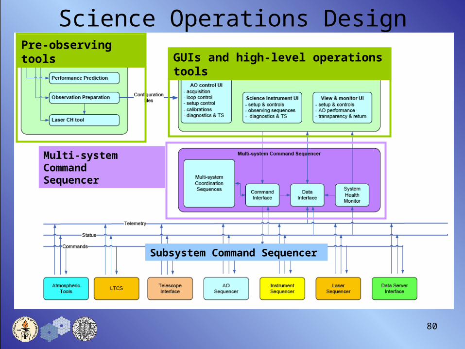
80
Pre-observing toolsGUIs and high-level operations tools
Multi-system Command Sequencer
Subsystem Command Sequencer
Science Operations Design

81
Control System Block Diagram
• Highly distributed control system• Client/Server relationships
between components, with master sequencer
• Communication paths identified• Communication protocols TBD

8282
Non-Real-Time Control Elements• Motion and bench automation control
– Field derotator
– Calibration source in/out
– Dichroic changers
– LGS WFS assembly
– LOWFS pickoff assembly
– Acquisition pickoffs
– Laser constellation configuration
– Laser pointing and centering
– Etc.
• Device control– Sensors configuration control (HOWFS, LOWFS, …)
– Device power control (DMs, cal sources…)
– Environmental control (temperature, humidity, particulates, cooling)
– Laser diagnostics sensors and power/environment control
82
Within a uniform motion control architecture and design approach•Standardization of motors/servos•Uniform specs for electronic drives•Electronics location requirements•Reliability specifications

83
Flowed-Down Real-Time Control Features• Performs high speed tomography of the atmosphere
– Up to 9 LGS, 3 LOWFS (2 tip/tilt, 1 tip/tilt/focus/astigmatism) sensors– Up to 11 DMs (woofer, narrow field tweeter, 6 d-IFS tweeters, 3 LOWFS tweeters– Multiple atmospheric layer tomography– Up to 2kHz frame rate
• Incorporates external parametric information– Cn2 (atmospheric) profile– Sodium layer profile– Wind profile
• Flexible with science observing mode– Variable LGS constellation
• Optimize for narrow and wide field– Arbitrary tip/tilt star locations and magnitudes
• “Point and shoot” option– NGS narrow field
83

8484
Real-time Control Architecture
• Massively parallel processor (MPP) implementation is the only feasible approach
• All aspects of the RTC algorithms have been analyzed and mapped to MPP implementation
84
ImageProcessors
ImageProcessorsImage
ProcessorsImageProcessors
WavefrontSensorsWavefrontSensorsWavefront
SensorsWavefrontSensors
TomographyUnit
ImageProcessorsImage
ProcessorsImageProcessorsDM
Fit
WavefrontSensorsWavefrontSensorsWavefrontSensors
DMProjection
DM field positionCn2 profile
Actuator influencefunction
Centroid algorithmr0, guidstar brightness,
Guidestar position
ImageProcessorsImage
ProcessorsImageProcessorsDeformable
Mirrors
Kolmogorovspectrum
Layer heightsGuide starheight
RTC top level of parallelization

85
Reviewer Q & A
• Start with control block diagrams requested by Fugate.

8686
Science Inst
Science Inst
Tweeter
Tweeter
LGS Wide Field Tomography Woofer/Tweeter MOAOFeeding Deployable Integral Field Spectrographs (d-IFS)
LGSWFS (9)
LOWFS (3)
Woofer & TT
Tweeter & TT (6)
d-IFS (6)
-
+-
+
Deployable on the field
LOWFSTweeter & TT (3)
-
+
W
W
W-T
TTomogRecon
TruthWFS

87
LGS Narrow Field Woofer/TweeterFeeding IFU, Vis and NIR Imagers
LGSWFS (9)
LOWFS (3)
Woofer & TT
Tweeter & TT
ScienceInst
-
+-
+
LOWFSTweeter & TT (3)
-
+
W
W
W-T
TTomogRecon
Truth WFS

88
Point and Shoot OptionFeeding IFU, Vis and NIR Imagers
LGSWFS (6)
LOWFS (3)
Woofer & TT
Tweeter & TT
ScienceInst
-
+-
+
LOWFSTweeter & TT (3)
-
+
W
W
W-T
TTomogRecon
LGSWFS (3)
WF Recon-structor
Truth WFS

89
NGS Narrow Field Woofer/Tweeter
NGSWFS
Woofer & TT
Tweeter & TT
ScienceInst
-
+
-
+
W
W W-T
T
WF Recon-structor

90
Brent Ellerbroek's "Big Three" Questions
1. Is the requirement for order 64x64 LGS wavefront sensing realistic, and how is it driving the design?• Yes, it is realistic. To be discussed in the performance section.• Drove us to a cascaded relay (or alternatively a split relay).
2. Can the MOAO/MCAO tradeoff be quantified further in terms of the performance - science - technical risk - programmatic risk - cost metrics that are defined in the report?• See answers in design, performance, risk & cost sections.
3. Is it too ambitious to develop a single AO system design for both the narrow field and wide(r) field applications?• We initially proposed a single large relay.• Five architectures were evaluated during the system design.• The large relay received a low ranking for several reasons including
size and cost.

9191
Q&A: 64x64 Wavefront SensingIs 64x64 LGS wavefront sensing realistic, and how is it driving the design?
• Drives the design in the following ways:• DM clear aperture sets the 2nd relay beam size• 64x64 LGS & NGS WFS needed for high Strehl science• All the LGS WFS will need to accommodate the wavefront spatial
sampling (at least 256x256 assuming a square grid CCD)• See performance section for more
• 32x32 fall-back impact:• Reduces 2nd relay beam size from 20 to 10 mm, making space for
instrument switchyard smaller & mechanically more difficult to design.• Relaxes requirements on number of LGS & NGS CCD pixels• DM less costly
• WFS risks: 240x240 PN sensor available. Baseline 256x256 CCID-56 under development.

92
Q&A: Addressing MEMS Risk4K Device (engineering grade) has been delivered to GPI
92
DM will be mounted on a tip/tilt stage
Mount design concepts under consideration

93
Cooling the Boston Micromachines MEMS does not appear to be a problem
• Source: Steve Cornelisson, Boston Micromachines
• Deflection vs. voltage is temperature independent, +20 C to -30 C
• For Nusil adhesive, no temperature effect on rms surface figure, +24 C to -30 C

94
Q&A: MOAO vs MCAOQ: MOAO/MCAO trade study not adequately quantified. MCAO should
be considered further, particularly if (i) fold mirror at an appropriate conjugate & (ii) order 64x64 wavefront correction not practical due to laser power. Impact on WFE budget if increased DM projection error for MCAO traded against MOAO implementation errors?
94
• KAON 499 multi-parameter scoring system used instead of KAON 452 metrics for the architecture decision.
• MOAO benefits are pretty clear from Figure
• Science cases require significantly reducing the generalized anisoplanatism error, driving an impractical number of MCAO DMs.
• DM projection & open loop go-to error are characterized & are significantly smaller (~30 nm for go-to, ~50 nm for implementation now verified on-sky)

9595
Q&A: MEMS CalibrationQ: What is your plan to calibrate the MEMs control in open loop?
BMC 144 actuator MEMS successfully calibrated at LAO. The open-loop performance of this same mirror has been confirmed on-sky in the Villages experiment. A similar approach will be taken with the 32x32 & 64x64 MEMS.

9696
Q&A: RTC ChallengeQ: NGAO is clearly a challenging system from the point of view of Real
Time Computer. … concerned by the fact that FPGA does not offer large flexibility during optimization of the AO system. … new ideas or new ways to control these systems will significantly evolve … flexibility in the SW implementation should be considered ...
• MPP design approach based on breaking down problem into basic key algorithms & allowing a maximum of flexibility in combining building blocks.
• Design will allow either of the presently proven stable LTAO algorithms: Fourier-Domain Pre-conditioned Conjugate Gradient Back Projection Tomography, and V-cycle Multi-grid Spatial Domain.
• Design will allow full flexibility in number of modeled atmospheric layers, number of subapertures in wavefront sensors, number of DMs, DM architecture (MOAO or MCAO), a-priori Cn2 model, asynchronous WFS frame rates, etc.
• The needed compute power scales with "problem size" (e.g. number of layers or number of subapertures) but the MPP architecture can track this with additional identical FPGA-populated boards & maintain the overall system throughput rate.

97
NGAO SDR Agenda10:00 Introduction & Presentation Approach (Wizinowich)10:05 Science Cases & Science Requirements (Max) SCRD11:15 Break11:30 Requirements (Wizinowich) SRD,FRD12:00 Design (Gavel) SDM12:30 Lunch13:30 Design Q&A (Gavel) SDM14:00 Performance Budgets (Dekany) SDM14:45 Project Management (Wizinowich) SEMP15:15 Risks (Wizinowich) Risk
KAONs15:45 Break16:00 Cost Estimate (Dekany) SEMP16:40 PD Schedule & Budget (Wizinowich) SEMP
+ Phased Implementation17:20 Conclusion (Wizinowich)17:30 General Discussion & Questions (Hubin et al.)18:00 End

Performance BudgetsPerformance Budgets

99
Charge 2&3: Performance• Charge 2: “Assess … the completeness & consistency of the technical
requirements.”– “Are the performance & error budgets complete & consistent with the
science requirements?”• Charge 3: “Evaluate the conceptual design for technical feasibility &
risk, & assess how well it meets the scientific & technical requirements.”– “Does the performance predicted for the conceptual design meet the
scientific and technical requirements given in the System Requirements document?”
– “If the predicted performance of the conceptual design does not meet the scientific or technical requirements are there adequate plans for addressing these deficiencies as the project continues?
• NGAO Team response:– The NGAO team has developed and is utilizing a capable set of well
anchored error budget and simulation tools to understand and evaluate performance, and to optimize the design.
• Additional improvements to these tools are planned for the PD.– The predicted performance meets the science requirements.
• But not all the high contrast goals.– Astrometry performance tools need to be developed during PD.

100
Performance Budgets and ToolsKAON # Detailed Efficient Analytical Key Design
System Spreadsheet Relationships DriversPerformance Budget Simulation Tool or Code Documented Identifed
Residual wavefront error 471 Ensquared energy 471 Transmission and background radiation 501 -- High-contrast observations 497 1 1 Astrometric precision 480 2,3 PD Photometric precision 474 2,3 -- -- Polarimetric precision -- -- -- 4
Efficiency Budget
Observing efficiency 463 5 PD PD System uptime PD -- PD PD x
Overall summary of SD activities 491
Legend Mature capability; will continue to evolve as requiredx Initial capability; will continue to develop in PD phase
PD No current capability; will develop during PD phase-- Not planned
Notes1 Further analysis of high-contrast performance requires coordination with the NIR and visible
coronagraph instruments.2 Will support via detailed, Monte Carlo simulation-based PSF libraries (LAOS, Arroyo)3 Used for a posteriori performance verfication; we do not plan to use for requirements flowdown4 PD phase support for Keck interferometer only5 During the DD phase, we may implement a prototypical simulation of AO observing sequences.
KAON # Detailed Efficient Analytical Key Design System Spreadsheet Relationships Drivers
Performance Budget Simulation Tool or Code Documented Identifed
Residual wavefront error 471 Ensquared energy 471 Transmission and background radiation 501 -- High-contrast observations 497 1 1 Astrometric precision 480 2,3 PD Photometric precision 474 2,3 -- -- Polarimetric precision -- -- -- 4
Efficiency Budget
Observing efficiency 463 5 PD PD System uptime PD -- PD PD x
Overall summary of SD activities 491
Legend Mature capability; will continue to evolve as requiredx Initial capability; will continue to develop in PD phase
PD No current capability; will develop during PD phase-- Not planned
Notes1 Further analysis of high-contrast performance requires coordination with the NIR and visible
coronagraph instruments.2 Will support via detailed, Monte Carlo simulation-based PSF libraries (LAOS, Arroyo)3 Used for a posteriori performance verfication; we do not plan to use for requirements flowdown4 PD phase support for Keck interferometer only5 During the DD phase, we may implement a prototypical simulation of AO observing sequences.

101
NGAO Performance
ObservationTT
refer-ence
LGS asterism
dia.
TTerror(mas)
SkyCover-
age
HOWFE(nm)
Eff.WFE(nm)
HStrehl
/ EE
KStrehl/ EE
IoScienceTarget NGS 2.7 NGS 104 112 83% 90%
KBO Companion Survey
FieldStar 11” 4.7 10% 154 175 64% 78%
Exo-Jupitersw/ LGS
ScienceTarget 11” 2.4 N/A 152 157 69% 82%
Galaxy /Galaxy Lensing
FieldStar 11” 9.5 30% 159 226 47% 66%
High-RedshiftGalaxies
FieldStar 51” 9.3 30% 204 257 55% 63%
Galactic Center IRS 7 11” 3.0 N/A 177 184 61% 76%
All but 1 case assume 100WHigh-redshift galaxies 150W

102
Reviewer Q & A

103
Q&A: WFE Budget Tool• WFE budget tool treats a wide variety of physical effects at appropriate
levels of detail for our major design decisions. It includes:– Estimates based on first principles (e.g. DM fitting error)
– Estimates based on real optical measurements • e.g. static & dynamic telescope errors
– Estimates based on parametric models grounded in more detailed stand-alone numerical codes (Monte Carlo simulations)
• e.g., background model, LGS tomography (3 independent codes compared), LOWFS architecture & sky coverage
– Key interactions between systems • e.g. LOWFS NGS sharpening, LGS WFS degradation by Rayleigh backscatter
• WFE budget tool has been anchored against:– Independent Keck AO WFE budget
– On-sky NGS & LGS performance of Keck & Palomar AO systems

105
Q&A: LGS WFS CCD noise has moderate performance impact(in part due to high SNR for good WF measurement)
Gal / Gal Lensing Performance vs. LGS WFS CCD noise(for 100W, 3+3 LGS WFS, 64x64 subaps, 4x4 pixels/subap, simple
0
50
100
150
200
250
300
0 2 4 6 8 10 12
RON [e-, rms] @ optimal rate
Tota
l equiv
ale
nt
WFE [
nm
]
0
200
400
600
800
1000
1200
1400
1600
1800
Opti
mal LG
S W
FS
Fra
me
Rate
[H
z] High-order WFE
Total WFE
Optimal frame rate
Benefit of optimal centroiding algorithms not shown
These curves are for read noiseIndependent of frame rate - we
usually link these through adetailed CCD noise model
170 nm requirement

106
Gal / Gal Lensing Performance vs. LOWFS read noise(for 100W, 3+3 LGS WFS, 2 TT + 1 TTFA, 2x2 pixels/subap, 30% sky, simple centroiding)
0
2
4
6
8
10
12
0 2 4 6 8 10 12 14 16
RON [e-, rms] @ optimal rate
Tota
l T
T E
rror
[mas]
0
100
200
300
400
500
600
700
Op
tim
al LO
WFS
Fra
me
Rate
[H
z]
TT Error [mas]Optimal frame rate
Q&A: IR LOWFS noise has modest performance impact(in part due to flexure, other TT error terms)
For this science case, 15 mas TT requirement met across range of LOWFS read noises
(Tightest requirement (Gal Center) also has brightest IR TT star)

107
Q&A: Number of Subapertures / Rates
“150W… seems inadequate… for up to 9… beacons, 17cm subapertures, and up to 2000 Hz frame rates.”
– Order 64x64 wavefront sensing/correction drives complexity of many other systems…
• True, but this combination of parameters is not an optimal performance point– Optimum WFE is found at N = 64 & 1055 Hz
• For half this sodium return, optimum is N = 58 (19 cm) & 908 Hz
• Design includes selectable pupil samples, N=16, 32, and 64 • Design drivers / Rationale
– N=64 correction intended to reduce telescope fitting error and to provide a large dark hole and fine control of residual PSF speckles
– N=64 WFS is optimal for bright NGS, less so for LGS (but N.B. future uplink AO)
– 2,000 Hz frame rate needed for bright NGS, high-contrast (where latency speckles are more insidious then noise speckles), and outlying Greenwood frequencies (where we accept larger WFE)

108Error budget corresponding to reviewer’s questioned scenario:
150W SOR, 9 beacons, 2,000 Hz frame rate, N=64 WFS’ing, 4e9 Na
Keck Wavefront Error Budget Summary Version 1.35
Mode: NGAO LGS
Instrument: TBD mSci. Observation: KBO m
/D (mas)
Atmospheric Fitting Error 48 nm 64 SubapsBandwidth Error 30 nm 100 Hz (-3db)High-order Measurement Error 107 nm 150 WLGS Tomography Error 37 nm 9 beacon(s)Asterism Deformation Error 22 nm 0.50 m LLTMultispectral Error 22 nm 30 zenith angle, H bandScintillation Error 13 nm 0.34 Scint index, H-bandWFS Scintillation Error 10 nm Alloc
131 nmUncorrectable Static Telescope Aberrations 43 nm 64 ActsUncorrectable Dynamic Telescope Aberrations 17 nm Dekens Ph.DStatic WFS Zero-point Calibration Error 25 nm AllocDynamic WFS Zero-point Calibration Error 40 nm AllocLeaky Integrator Zero-point Calibration Error 15 nm AllocGo-to Control Errors 38 nm AllocResidual Na Layer Focus Change 34 nm 30 m/s Na layer velDM Finite Stroke Errors 0 nm 4.0 um P-P strokeDM Hysteresis 13 nm from TMTHigh-Order Aliasing Error 16 nm 64 SubapsDM Drive Digitization 1 nm 16 bitsUncorrectable AO System Aberrations 30 nm AllocUncorrectable Instrument Aberrations 30 nm TBD InstrumentDM-to-lenslet Misregistration 15 nm AllocDM-to-lenslet Pupil Scale Error 15 nm Alloc
99 nmAngular Anisoplanatism Error 23 nm 1.5 arcsec
Total High Order Wavefront Error 164 nm 166 nm High Order Strehl
ParameterWavefrontError (rms)
Science High-order Errors (LGS Mode)

109
NGAO Major Error Terms Depending on Subaperture Sampling
(for KBO science case, r0 @ 30 zen =14.7 cm, 100W SOR power, median LGS spot size ~1.71", 3 Sci Ast + 3 PnS Ast WFS's @ fixed 1000 Hz)
0
20
40
60
80
100
120
0 10 20 30 40 50 60 70 80
Number of Actuators Across Telescope Diameter
rms
WFE
[n
m] Telescope Fitting Error
Measurement Error
Atm Fitting Error
RSS Sum

110
Q&A: MOAO PnS vs. MCAO for TT sharpening
• “What is the quantitative impact on sky coverage if the PnS lasers are eliminated from the system?”– “What is the impact if MOAO is replaced with MCAO?”
• Both questions are directed to the benefits of superior sharpening of IR WFS NGS’s
• Assumptions– NGAO IR WFS NGS MOAO PnS sharpening model
• Interior to the Science Asterism– No anisoplanatism, constant tomography error
• Exterior to the Science Asterism– Tomography error transitions smoothly to single-LGS focal anisoplanatism error
– NGAO IR WFS NGS MCAO sharpening model• Interior to the Science Asterism (which must be expanded to increase NGS sharpening)
– No anisoplanatism, increased constant tomography error
• Exterior to the Science Asterism– Fall off as normal single-conjugate anisoplanatism: ~ ((sci_aster) / 0_eff)5/6

111
NGS Sharpening Model
(for KBO science case, r0 @ 30 zen =14.7 cm, 100W SOR power, median LGS spot size ~1.71",N=32 actuators, 38 nm Go-To errors (MOAO), 1060 Hz,
3 Sci Ast 3 on 5" radius + 3 PnS Ast at NGS (MOAO) OR "5+1" Sci Ast on 21" radius (MCAO))
0.00
0.10
0.20
0.30
0.40
0.50
0.60
0 10 20 30 40 50 60 70
Off-axis distance [arcsec]
J-band S
trehl R
ati
o
MOAO
MCAO
Extending sci asterism further pushes ‘roll-off’ edge outward at cost of greater tomography error in the science direction
Going from 5 to 21” in this example increased sci direction tomography error from 54 nm to 70 nm
112
Q&A: MOAO PnS vs. MCAO for TT sharpening
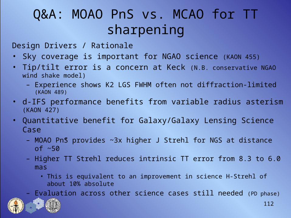
Design Drivers / Rationale• Sky coverage is important for NGAO science (KAON 455)
• Tip/tilt error is a concern at Keck (N.B. conservative NGAO wind shake model)
– Experience shows K2 LGS FWHM often not diffraction-limited (KAON 489)
• d-IFS performance benefits from variable radius asterism (KAON 427)
• Quantitative benefit for Galaxy/Galaxy Lensing Science Case– MOAO PnS provides ~3x higher J Strehl for NGS at distance of ~50”
– Higher TT Strehl reduces intrinsic TT error from 8.3 to 6.0 mas• This is equivalent to an improvement in science H-Strehl of about 10% absolute
– Evaluation across other science cases still needed (PD phase)

113
Q&A: MOAO PnS vs. MCAO for TT sharpening
Design Drivers / Rationale (cont.)• Better-corrected NGS PSF’s are operationally easier to handle
– More likely to obtain a diffraction-limited PSF core across a variety of environmental conditions
– More consistent core expected to improve acquisition efficiency
• Not all science targets follow Spagna statistics– c.f. GOODS-N/S, HDF N/S, Chandra DFS, Lockman Hole, COSMOS field– Design for wider NGS field of regard than indicated by Spagna average
values
• Cost / Benefit of PnS architecture (vs. scalable but fixed geometry asterism) is subject of a preliminary design study

114
Q&A: Sodium Layer Photoreturn• Basic assumption (based on published SOR measured return)
– 150 ph/cm2/s/W
• Explicit assumptions– All lasers contribution to science wavefront calculation
• Worst case Point-and-Shoot laser is ~75” off-axis. The “10% metapupil shear height” at this angle is ~3 km, which is above ~80% of the turbulence in the MK Ridge model. The claim therefore that the PnS LGS sample most of the save volume as the science asterism, so their photons also count.
– During the PD phase, this will be confirmed using detailed LAOS simulations.
– Transmission(s)• Up: LGSF 0.75 x Atm30 up 0.78 = 0.59• Down: Atm30 down 0.78 x Telescope 0.61 x NGAOHOWFS 0.37 X HOWFS QE589
0.80 = 0.14
• Implicit assumptions– SOR technology (or its equivalent) can be made available to NGAO– NGAO lasers will be backpumped and return will be invariant across
different magnetic field lines

115
NGAO Performance vs. Photoreturn
0.25
0.30
0.35
0.40
0.45
0.50
0.55
0.60
0.65
0.70
0.75
0 0.25 0.5 0.75 1 1.25 1.5 1.75 2
Relative photoreturn(1 = baseline; 150 ph/cm2/s/W, 100W, 4e9 cm-2 Na)
H-S
tre
hl
N = 64 KBON = 32 KBON = 64 Gal Gal LensN = 32 Gal Gal Lens
At each data point, the frame rate that minimized WFE is used (ranging from 425 fps to 1886 fps)
NGAO performance is robust to fluctuations in laser photoreturn(from Na column density, laser return per W, or laser power)
For only 50W laser power, performance pivots around relative photoreturn = 0.5; not acceptable
H
Str
ehl

116
NGAO SDR Agenda10:00 Introduction & Presentation Approach (Wizinowich)10:05 Science Cases & Science Requirements (Max) SCRD11:15 Break11:30 Requirements (Wizinowich) SRD,FRD12:00 Design (Gavel) SDM12:30 Lunch13:30 Design Q&A (Gavel) SDM14:00 Performance Budgets (Dekany) SDM14:45 Project Management (Wizinowich) SEMP15:15 Risks (Wizinowich) Risk
KAONs15:45 Break16:00 Cost Estimate (Dekany) SEMP16:40 PD Schedule & Budget (Wizinowich) SEMP
+ Phased Implementation17:20 Conclusion (Wizinowich)17:30 General Discussion & Questions (Hubin et al.)18:00 End

Project ManagementProject Management

118
Charge 5: Project Management
• Charge 5: Evaluate the suitability & effectiveness of the project management, organization, decision making …, with an emphasis on the next project phase (preliminary design) and also with respect to the entire project.– Does the performance of the project to date support the project’s approach
to management & decision making?
– Is the project’s proposed approach to management & decision making likely to succeed? What modifications would be advantageous to assure the success of the entire project?
• NGAO Team response:– SDR deliverables complete.
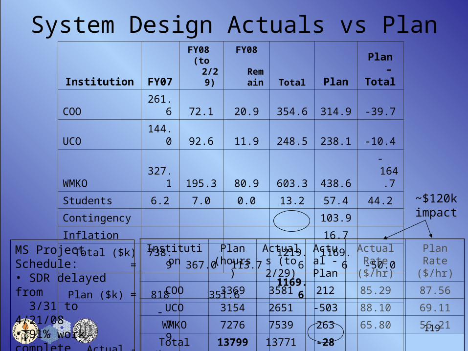
– 4% schedule & budget overruns (3 weeks & $50k).– ~7% of planned work postponed or cancelled (equivalent to ~$70k).– ~$120k used for higher than planned salary rates.
– Improved management/org structure defined for next phase.– Structure will be further strengthened for detailed design
119
System Design Actuals vs Plan
Institution FY07FY08
(to 2/29)FY08
Remain Total PlanPlan –Total
COO 261.6 72.1 20.9 354.6 314.9 -39.7
UCO 144.0 92.6 11.9 248.5 238.1 -10.4
WMKO 327.1 195.3 80.9 603.3 438.6 -164.7
Students 6.2 7.0 0.0 13.2 57.4 44.2
Contingency 103.9
Inflation 16.7
Total ($k) = 738.9 367.0 113.7 1219.6 1169.6 -50.0
Plan ($k) = 818 351.6 1169.6
Actual - Plan = -79.1 129.2 50.0
Institution Plan (hours)
Actuals (to 2/29)
Actual - Plan
Actual Rate ($/hr)
Plan Rate ($/hr)
COO 3369 3581 212 85.29 87.56
UCO 3154 2651 -503 88.10 69.11
WMKO 7276 7539 263 65.80 56.21
Total (hrs) = 13799 13771 -28
MS Project Schedule:• SDR delayed from 3/31 to 4/21/08• 91% work complete thru SDR
~$120kimpact

120
Organization Structure

121
Decision MakingOrganization structure assigns responsibilities/authority:• Clear requirements & interfaces should facilitate localized technical decision making.• Systems engineering flows down requirements, interface definitions & architecture, &
evaluates changes.• PM makes or delegates project decisions, in consultation with senior NGAO management.
• Direction & consultation on major changes (funding, cost, schedule or requirements) &
priorities (schedule, budget &/or requirements) will be sought from WMKO Directorate. • Science consultation with SSC as needed.
Decision making falls into several categories:• Configuration control
– Requirements & interface definitions will be under configuration control immediately, & designs starting during Detailed Design.
– Change Control Board reviews & approves changes to the above starting in Detailed Design.– Science & System Requirement changes additionally approved by Project Scientist & PM.
• Risks– Risks will be tracked by PM & Systems Eng. Decisions to retire risks early wherever possible.
• Build versus Buy– Need to determine any constraints imposed by the Directors.– Prefer to buy when we can at a level existing vendors have demonstrated their ability to deliver.
• Reviews (provide input to the Directors & NGAO team for decision making)– Project reviews provide an opportunity to review project decisions at key milestone points.– Monthly report, SSC presentations & meetings with the Directorate.

122
Charge 6&7: Project Management
• Charge 6: Provide feedback on whether the overall strategy will optimize the delivery of new science.
• Charge 7: Gauge the readiness of the project to proceed to the preliminary design phase.– Has the project adequately defined the objectives, work breakdown
structure & task plan for the next design phase?
• NGAO Team response:– Overall strategy optimizes science delivery.
– PD plan well defined.• Further improvements could be made starting with DD.

123
Work Breakdown Structure

124
Integration & Test
+ Reviews
18 months 6 mos24 mos
Milestones
PDR22 mos
SDR

125
Integration & Test
+ Reviews
6 mos 6 mos 4 mos
AO Unavailable (12 mos)Milestones

126
Reviewer Q & A

Technical & Programmatic RisksTechnical & Programmatic Risks& Risk Mitigation& Risk Mitigation

128
Charge 3&5: Risk
• Charge 3: “Evaluate the conceptual design for technical feasibility & risk, & assess how well it meets the scientific & technical requirements.”
• Charge 5: Evaluate the suitability & effectiveness of the project management, organization, decision making & risk mitigation approaches, with an emphasis on the next project phase (preliminary design) and also with respect to the entire project.
• NGAO Team response:– The technical & programmatic risks have been identified and
ranked, and will be tracked.– Risk mitigation approaches have been identified.
• Risk mitigation during PD funding limited.

129
Risk Overview
1. Inadequate PSF calibration2. Inadequate sky coverage3. Required lasers unavailable4. WFE budget assumptions5. Inadequate tomographic reconstruction6. Astrometric performance7. Tomographic computer HW architecture8. Keck Interferometer needs9. SW control complexity & instability10. CCD availability
5
4 4 1,2
3 20 11,12 5-8 3
2 21-22 13-19 9,10
1 24 231 2 3 4 5
L
ikel
iho
od
Consequences
5
4 5,6
3 10 7-9 3,4 1,2
2
1 1 2 3 4 5
L
ikel
iho
od
Consequences
Technical Programmatic
1. NGAO funding
2. Required lasers unavailable
3. Rapid project ramp up
4. Growth in cost estimate5. Lack of full-time personnel
6. Management structure
7. Science instruments schedule
8. Funding schedule impact
9. Contract schedule slips

130
Technical Risk Evaluation
1. Inadequate PSF calibration• Most impact on Galactic Center GR & narrow-field proper motion
astrometry, & detection of planets around low mass stars.a) Collaborate on CfAO-funded PSF reconstruction effortb) Produce a system-level design for PSF calibrationc) Investigate Mauna Kea atmospheric profiler collaboration
2. Inadequate sky coverage to support wavefront error budget• AO corrected low order wavefront sensing using low noise NIR
detectors assumed.a) NIR TT sensor to demo detector & AO correction. Investigate IRIS
LOWFS study collaborationb) Lab &/or on-sky demo during DD.
3. Required lasers unavailable• Sodium return inadequate. See programmatics risks.

131
Risk Mitigation with ongoing experiments at LAO/Mt Hamilton with ViLLaGEs*
• Objectives1. Test MEMS deformable mirrors on-sky2. Open-Loop AO3. Uplink-corrected laser projection
• Implementation– AO system on Nickel 40” telescope– 140-DOF BMC micro deformable mirror– CCD-39 WFS with simultaneous wavefront measurements
1. Uncorrected (Open loop) wavefront2. Closed loop residual corrected wavefront3. Sharpened tip/tilt star
*Visible Light Laser Guidestar Experiments
132132
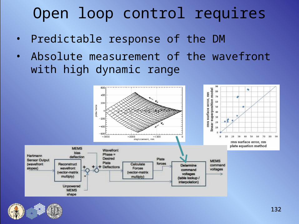
Open loop control requires
• Predictable response of the DM
• Absolute measurement of the wavefront with high dynamic range

133
Villages open-loop on-sky AO results
[Montage of open-loop controlled images in V, R, I, 900nm bands]
Strehl vs wavelengthOn-sky Data and Prediction Using Error
Allocation Model
Strehl vs wavelengthOn-sky Data and Prediction Using Error
Allocation Model
Error AllocationError Allocation
Internal Calibrator(650 nm)
900/40 nm I band (800 nm)
R band (600 nm) V band (500 nm)
Uncorrected
1”

135
Rejection Ratio of Temporal Power in the Wavefront Residuals
135
Closed Loop
Open Loop

136
Open vs Closed Loop Conclusions
• Open loop control has higher bandwidth• Closed loop control does better at low frequencies (consequence of
open loop cancelation accuracy)
• On sky, we noticed no difference in Strehl performance between open-loop and closed-loop operation
Take-Home Points• We now have on-sky experience with MEMS DMs• Open-loop control appears to be working in a way that is
consistent with NGAO error budget models
136

137
Programmatic Risk Evaluation
1. NGAO funding• Not a review item
2. Required lasers unavailable &/or too expensive• Business model for affordable SOR or LMCT-type lasers?a) Determine best laser availability solution b) Evaluate impact of procuring less laser power
3. Rapid project ramp-up• Rapid personnel ramp-up required after preliminary designa) Produce a viable ramp up planb) Find funds to allow more people to be involved earlier
4. Cost estimate growtha) Identify & exploit cost savings opportunitiesb) Employ a design to cost approach

138
Laser Systems
• NGAO laser procurement issues– Single frequency CW laser appears to produce the most return per watt
– All known systems require engineering development to be suitable for NGAO deployment
– TMT also needs lasers, it appears NGAO requirements can be harmonized with TMT requirements
– This creates a more realistic commercial opportunity for vendors
• NGAO laser procurement strategy– Develop harmonized requirements by collaborating with TMT
– Issue an RFP for laser system development• Start as early as possible with contract for laser engineering (detailed
design) phase
– Procure lasers in some way that allows vendor to build 6 x 50 watt, (or 12 x 25 watt) over some reasonable period for both NGAO and TMT
– Ensure reliable source of spare parts and long term support

139
Reviewer Q & A

140
NGAO SDR Agenda10:00 Introduction & Presentation Approach (Wizinowich)10:05 Science Cases & Science Requirements (Max) SCRD11:15 Break11:30 Requirements (Wizinowich) SRD,FRD12:00 Design (Gavel) SDM12:30 Lunch13:30 Design Q&A (Gavel) SDM14:00 Performance Budgets (Dekany) SDM14:45 Project Management (Wizinowich) SEMP15:15 Risks (Wizinowich) Risk
KAONs15:45 Break16:00 Cost Estimate (Dekany) SEMP16:40 PD Schedule & Budget (Wizinowich) SEMP
+ Phased Implementation 17:20 Conclusion (Wizinowich)17:30 General Discussion & Questions (Hubin et al.)18:00 End

Cost EstimationCost Estimation

142
Charge 4: Cost Estimate
• Charge 4: Assess whether the design can be implemented within the proposed schedule & budget.– Are the plans for completion of the project, including the cost
estimate, schedule & budget to completion, sufficiently detailed?– Is the methodology used to develop the cost estimates sound?– Is the proposed budget to completion realistic?– Is there sufficient management reserve (contingency) allocated in
the proposed budget to completion?
• NGAO Team response:– A detailed and realistic bottoms-up cost estimate has been
prepared for the completion of the project and for each major phase, including identification of contingency.

143
Cost Estimation Methodology (KAON 546)
• Cost estimation spreadsheets– Based on TMT Cost Book approach, simplified for SD phase– Prepared for each WBS element (~75 in all)– Prepared for each of 4 phases
• Preliminary design, detailed design, full scale development, delivery/commissioning
– Prepared by technical experts responsible for deliverables– Process captures
• WBS dictionary• Major deliverables• Estimates of labor hours• Estimates of non-labor dollars (incl. tax & shipping) & travel dollars• Basis of estimate (e.g. vendor quote, CER, engineering judgment)• Contingency risk factors & estimates• Descope options
– Standard labor classes, labor rates & travel costs used

144
Cost Estimate to Completion (FY08 $k)
WBS WBS Title PD DD FSD D&CBaseCost
Contin-gency
Total($k)
2 Management 874 1,232 1,594 657 4,356 318 4,674
3 Systems Eng 811 1,004 478 193 2,485 401 2,886
4 AO System Dev 730 2,208 9,742 3 12,683 3,849 16,533
5 Laser System Dev 285 1,947 6,619 128 8,980 1,935 10,915
6 Science Operations 166 756 646 1,568 233 1,801
7 Tel. & Summit Eng. 95 424 1,049 19 1,587 344 1,932
8 Telescope I&T 46 106 114 1,944 2,211 525 2,735
9 Ops Transition 14 20 555 70 660 91 750
Sub-Totals ($k) 3,021 7,697 20,797 3,015 34,530 7,697 42,227
11%
7%
39%
26%
4%
5%
6%
2%
100%

145
Cost Estimate to Completion (FY08 $k)
PhaseLabor (PY)
Cost Estimate (FY08 $k)% of
NGAO BudgetLabor
Non-Labor
TravelSub-Total
Contin-gency
Total
Preliminary Design 21.0 2,582 216 224 3,022 458 3,479 8%
Detailed Design 43.6 5,516 1,827 354 7,697 1,403 9,100 22%
Full Scale Develop 50.5 5,661 14,510 626 20,797 5,234 26,031 62%
Delivery/Commission 22.4 2,287 250 478 3,015 602 3,617 9%
Total = 138 16,045 16,804 1,681 34,531 7,697 42,227 100%
% = 46% 49% 5% 100% 22% 122%

146
Reviewer Q & A

147
Q&A: Cost Impact of MOAO/MCAOfor TT Sharpening
• “What is the impact of the MCAO/MOAO tradeoff on the cost estimate, particularly if the order of correction were scaled back to 32x32 or 20x20?”
• Cost increments for MCAO vs. MOAO for purpose of NGS sharpening
– Savings ~$2,100K?• Remove three LOWFS 32x32 MEMS: ~$500k hardware• Reduce RTC requirements: ~$600k hardware• Reduce LOWFS Assembly, I&T, RTC & Commissioning labor: ~$1,000k?
– Increases ~$1,700K - $2,600K?• 20x20 or 32x32 9 km conjugate DM: $300k or $1200k.• Increase RTC requirements: ~$400k hardware(?)• Increase Optical Relay, I&T, RTC, Commissioning labor: ~$1,000k?

148
Q&A: Cost Impact of MOAO/MCAOfor Science
• Achieving science goals with MCAO requires somewhat different approach (KAON 452)
• N = 64 x 64 actuators for narrow-field science path (KAON 499)
– DM with appropriate pitch and large stroke unavailable– Result drives architecture toward our MCAO “Large Relay” option
• Incremental cost comparison during architecture downselect indicated that Large Relay was ~$2.6M greater cost than Cascaded Relay
• MOAO would likely still be required for dIFS (KAON 471)
– 2’ circular field of regard suffers from generalized anisoplanatism, not present in MOAO architecture
• Details have not been quantified, but using MOAO we barely meet the dIFS performance requirements
• MOAO could be avoidable over ~60” field of regard
– d-IFS impact was not considered in earlier cost comparison

Schedule & BudgetSchedule & Budget

150
Charge 4&7: Schedule, Budget & Resources
• Charge 4: Assess whether the design can be implemented within the proposed schedule & budget.
• Charge 7: Gauge the readiness of the project to proceed to the preliminary design phase.– Are the resources identified for the next design phase sufficient to
address the scope of work?
• NGAO Team response:– This section will only address the PD phase (the rest of the project
has been addressed in earlier sections)– A realistic budget and schedule has been produced for the PD
phase.– Excellent team for PD. Resources are sufficient.
• Will need more full-time effort starting with DD.

151
Preliminary Design Phase Schedule
• PD phase tasks & hours from cost estimation entered in MS Project.• Personnel assigned to tasks.• Tasks scheduled in required sequence & in order to fit within FY
available budgets.

152
Preliminary Design Budget (FY08 $k)
Institution
Work (hours) Cost ($k)
FY08 FY09 FY10 Total FY08 FY09 FY10 Total
COO 1116 4360 927 6403 107 419 88 614
UCO 1719 6407 1675 9801 113 444 118 675
WMKO 2542 11633 3030 17204 196 841 228 1264
Free (Max + WMKO) 292 1068 203 1563 0 0 0 0
Student/Postdoc 227 933 0 1160 9 37 0 46
Labor Total = 5895 24401 5835 36131 425 1741 434 2600
Procurements ($k) 2 164 50 216
Travel ($k) 28 125 61 214
Labor & Non-Labor Total ($k) = 30 289 111 430
Contingency ($k) 0 0 449 449
Total ($k) = 455 2030 994 3479
Available ($k) = 455 2000 1024 3479
Available - Total ($k) = 0 -30 30 0

153
Preliminary Design Core TeamName Inst Role %
Adkins, Sean WMKO Laser procurement, instrument interfaces 26
Bell, Jim WMKO AO enclosure & infrastructure 23
Britton, Matthew COO Wavefront sensor design, performance budgets 24
Dekany, Rich COO COO project management, systems engineering 52
EE / Programmer UCO Real-time control 78
Gavel, Don UCO UCO project management, technical overview 37
Johansson, Erik WMKO Non-real time controls & software, systems eng 89
Kupke, Renate UCO AO optical design 25
Le Mignant, David WMKO Science operations tools, operations concept 93
Lockwood, Chris UCO AO mechanical design 36
Max, Claire UCO Project Scientist, science requirements development 35
McGrath, Elizabeth UCO Postdoc for Project Scientist, science development 100
Morrison, Doug WMKO Non-real time control software 25
Neyman, Chris WMKO Systems engineering, laser & AO facility design 84
Velur, Viswa COO Wavefront sensor design 58
Wetherell, Ed WMKO Non-real time control electronics 34
Wizinowich, Peter WMKO Project manager, technical overview 59
Zolkower, Jeff COO Wavefront sensor design 28
EC
Full-time

154
Reviewer Q & A

Phased ImplementationPhased Implementation
156
Charge 6: Staged Implementation/Descopes
• Charge 6: Provide feedback on whether the overall strategy will optimize the delivery of new science.– Are there possibilities for staged implementation or descopes that
are viable in terms of the science requirements?
• Disclaimer: Not a System Design phase deliverable.– Some initial thoughts presented here.
– Options can be considered during Preliminary Design.
– Staged implementation will be more expensive, but allows science return as funding available.

157
One Phased Approach OptionPhase 1: Laser tomography• 50W laser, fewer LGS• fewer LGS WFS & LOWFS• no MEMS or MOAO control• no new instruments• uncooled enclosure Higher SR from laser power &
reduced focal anisoplanatism
Add back based on science priority
RTC
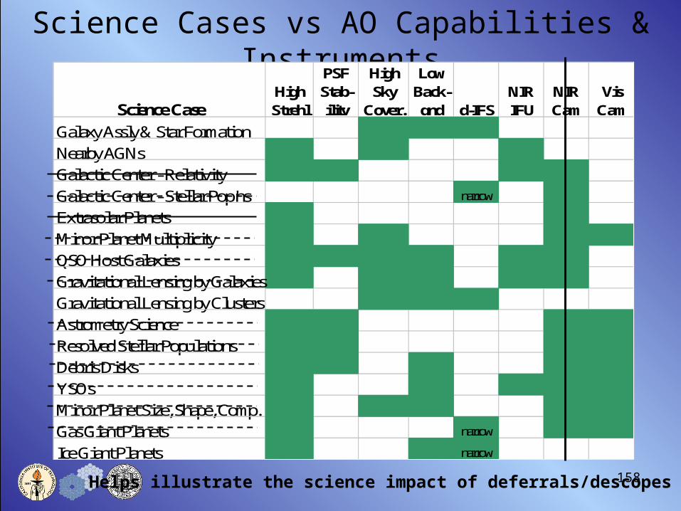
158
Science Cases vs AO Capabilities & Instruments
Helps illustrate the science impact of deferrals/descopes
Science CaseHigh Strehl
PSF Stab-ility
High Sky
Cover.
Low Back-gnd d-IFS
NIR IFU
NIR Cam
Vis Cam
Galaxy Assly & Star FormationNearby AGNsGalactic Center - RelativityGalactic Center - Stellar Pop'ns narrow
Extrasolar PlanetsMinor Planet MultiplicityQSO Host GalaxiesGravitational Lensing by GalaxiesGravitational Lensing by ClustersAstrometry ScienceResolved Stellar PopulationsDebris DisksYSOsMinor Planet Size, Shape, Comp.Gas Giant Planets narrow
Ice Giant Planets narrow

159
Reviewer Q & A

160
Review Panel Report Questions1. Assess the impact of the science cases in terms of the competitive landscape in which the
system will be deployed. – Science section
2. Assess the maturity of the science cases & science requirements and the completeness & consistency of the technical requirements. – Science, Requirements & Performance sections
3. Evaluate the conceptual design for technical feasibility & risk, & assess how well it meets the scientific & technical requirements.– Design, Performance & Risk sections
4. Assess whether the design can be implemented within the proposed schedule & budget.– Cost & PD Schedule & Budget sections
5. Evaluate the suitability & effectiveness of the project management, organization, decision making & risk mitigation approaches, with an emphasis on the next project phase (preliminary design) and also with respect to the entire project.– Project Management & Risk sections
6. Provide feedback on whether the overall strategy will optimize the delivery of new science.– Project Management & Phased Implementation sections
7. Gauge the readiness of the project to proceed to the preliminary design phase.– Design, Project Management & PD Schedule & Budget sections

161
Conclusion• NGAO will provide the WMKO community with a powerful & unique
scientific capability.• The requirements are well understood & have been flowed down to
the design.• A feasible and optimal conceptual design has been developed.• The technical and programmatic risks are well understood.• A solid cost estimate has been developed.• The management structure, plan and personnel are in place for the
preliminary design.
• The very significant scientific rewards offered by NGAO come with significant technical & programmatic challenges.
• We have a team capable of addressing these challenges and delivering this powerful new scientific capability.
• We are ready, willing & able to proceed with the preliminary design.

162
NGAO SDR Agenda10:00 Introduction & Presentation Approach (Wizinowich)10:05 Science Cases & Science Requirements (Max) SCRD11:15 Break11:30 Requirements (Wizinowich) SRD,FRD12:00 Design (Gavel) SDM12:30 Lunch13:30 Design Q&A (Gavel) SDM14:00 Performance Budgets (Dekany) SDM14:45 Project Management (Wizinowich) SEMP15:15 Risks (Wizinowich) Risk
KAONs15:45 Break16:00 Cost Estimate (Dekany) SEMP16:40 PD Schedule & Budget (Wizinowich) SEMP
+ Phased Implementation17:20 Conclusion (Wizinowich)17:30 General Discussion & Questions (Hubin et al.)18:00 End