1 modeling interactions and behavior lecturer dr. mai fadel
TRANSCRIPT

1
Modeling interactions and behavior
Lecturer Dr. Mai Fadel

2
Introduction
• An interaction model shows a set of actors and objects interacting by exchanging messages.
• A behavior model shows how an object or system changes state in reaction to series of events.

3
8.1 Interaction diagrams• Interaction diagrams are used to model the dynamic
aspects of a software system – they help to visualize how the system runs.
• They show how a set of actors and objects communicate with each other to perform the steps of a use case or some other piece of functionality.
• Interaction diagrams can show several types of communication. e.g. messages exchanged over a network, simple procedure calls, and commands issued by an actor through the user interface. Collectively these are referred to as messages.
• The following elements can be found in an interaction diagram:– Instances of classes or actors: use same symbols for objects
and actors– Messages: shown as arrows. One of the objectives of interaction
diagrams is to better understand the sequence of messages.
4
Sequence diagrams
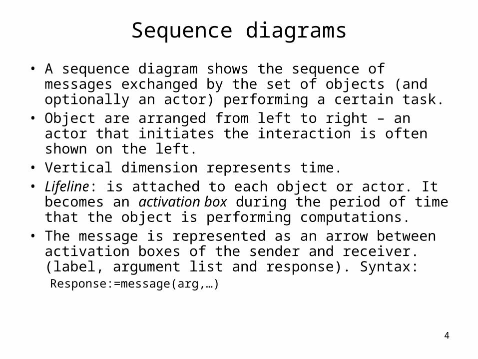
• A sequence diagram shows the sequence of messages exchanged by the set of objects (and optionally an actor) performing a certain task.
• Object are arranged from left to right – an actor that initiates the interaction is often shown on the left.
• Vertical dimension represents time.• Lifeline: is attached to each object or actor. It becomes
an activation box during the period of time that the object is performing computations.
• The message is represented as an arrow between activation boxes of the sender and receiver. (label, argument list and response). Syntax:Response:=message(arg,…)

5
Example: the process of the registration of a student in a course
+getPrerequisite()
Course
+requestToRegister()+addToRegistrationList()
CourseSection Registration
+addToSchedule()+hasPassedCourse()
Student*1 *1 *1
:CourseSection
:Registration
:Student
Top Package::Actor1
requestToRegistercreate
addToRegistrationList
addToSchedule

6
Example: the process of the registration of a student in a course – detailed level
:GUI :CourseSection
:Registration
aStudent:Student :Course
requestToRegister
RequestToRegister(a student)
prereq := getPreRequisite
hasPrerequisite := hasPassedCourse(prereq)
create
addToSchedule
addToRegistrationList
opt[hasPrerequisite]
7
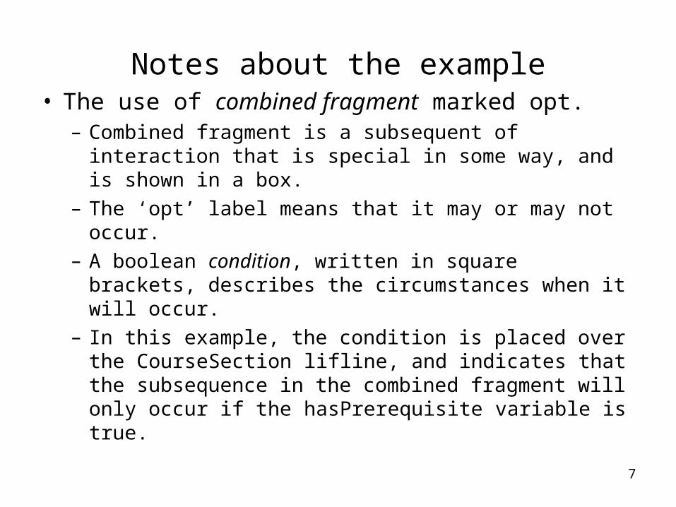
Notes about the example• The use of combined fragment marked opt.
– Combined fragment is a subsequent of interaction that is special in some way, and is shown in a box.
– The ‘opt’ label means that it may or may not occur. – A boolean condition, written in square brackets,
describes the circumstances when it will occur.– In this example, the condition is placed over the CourseSection lifline, and indicates that the subsequence in the combined fragment will only occur if the hasPrerequisite variable is true.

8
Representing loops in a combined fragment
Bill Purchase Item*1
* 1
:Bill
:Purchase :Item
getSubtotal
getUnitPrice
ComputeTotal
0..numPurchases
loop

9
Destroy symbol in sequence diagrams
:SpecificFlight :Booking :PassengerRole
cancelBooking
cancel
deleteFromItinerary
deleteFromPassengerList

10
Communication Diagrams
• A communication diagram shows several objects working together.
• It is very much like an object diagram except that it shows communication links instead of links of associations.
• It has much in common with sequence diagrams• Message: arrow with label, and a prefix number
showing the order of the message• Communication links can exist between two
objects whenever it is possible for one object to send a message to the other one.

11
:CourseSection :Registration :Student
2: addToSchedule1: create
3: addToRegistrationList
:GUI :CourseSection :Course
aStudent:Student :Registration
2:prereq := getPrerequisite1:requestToRegister(aStudent)<<local>>
5:addToSchedule<<parameter>>
3:hasPrerequisite :=hasPassedCourse(prereq)
<<parameter>>6:addToRegistrationList
<<parameter>>4:create

12
How to choose between using a sequence or a communication diagram
• Sequence diagrams are often the better choice for the following situations:– You want the reader to be able to easily see the order in which
the messages occur– You want to build an interaction model from use case. (they
already have a sequence of steps, SD shows the objects involved)
– You need to show the details of messages, such as parameters, and return values. (CD too much clutter)
– You need to show loops, optional sequences and other things that can only be properly expressed using combined fragments.
• Prefer CD when deriving interaction diagram from class diagrams. (CD are very similar to object diagrams)
• CD can be used to validate class diagrams: suggest adding an association in order to make an interaction possible.

13
State diagrams• Also known as state machine diagram• It is another way of expressing dynamic information about
a system• At any given point in time, the system or object is said to
be in a certain state. It remains in this state until an event occurs that causes it to change state.
• In each state, the system behaves in a different way.• A transition represents a change of state in response to
an event, and is considered to occur instantaneously –that is it takes no time.
• Symbols in state diagrams: rounded rectangles, arrows, labels on arrows, black circle, black circle with a ring around.
• A start state: when a system starts running, it immediately takes a transition from the start state to a regular state. Only one start state and one unlabelled transition from it.
• End state: when the system finishes its work when such a state is reached. More than one end state.

14

15
Elapsed-time transition
The event that trigger a transition can be a certain amountof elapsed time.
after (30s)
• No end state
16
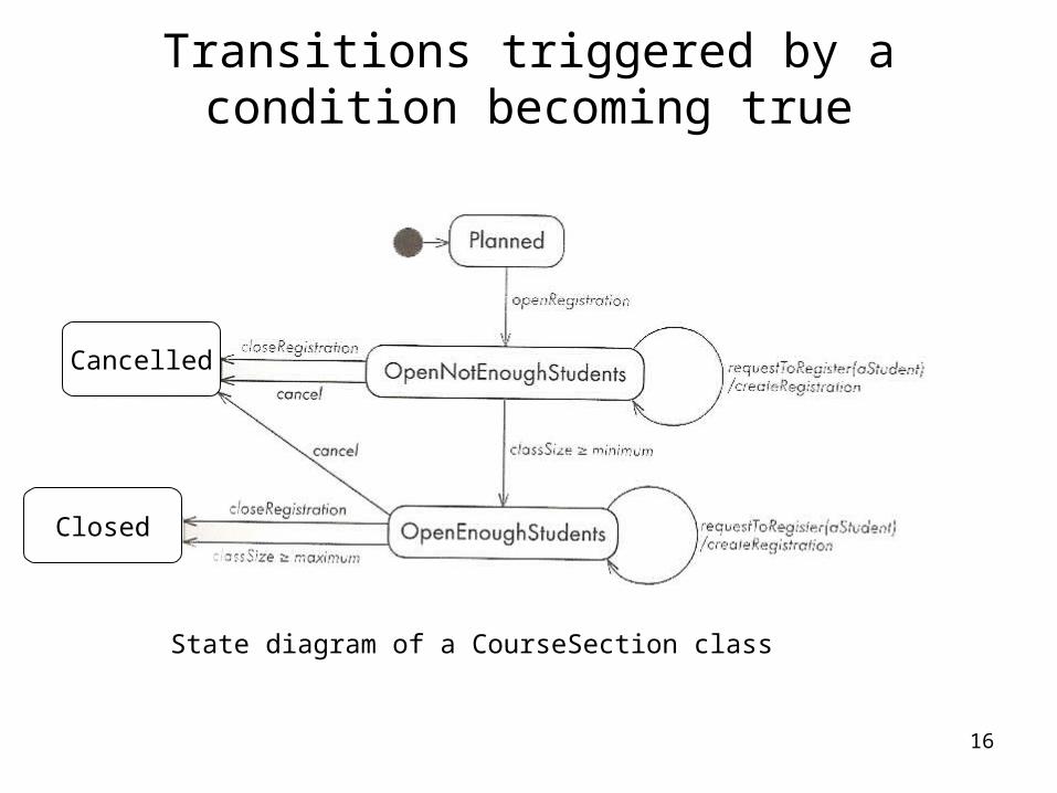
Transitions triggered by a condition becoming true
Cancelled
Closed
State diagram of a CourseSection class
17
Activities and actions in state diagrams
• You can present two kinds of computations using state diagrams: activities and actions.
• Activity is something that occurs over a period of time while the system is in a state.– The system may take a transition out of the state in
response to completion of the activity.– If some other transition is triggered first, then the
system has to terminate the activity as it leaves the state
– It is shown textually by the word do/, followed by the description of what is to be done.
18
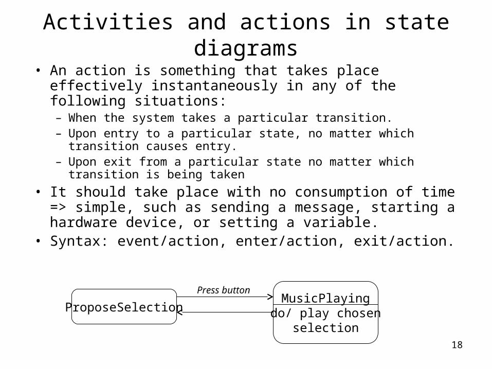
• An action is something that takes place effectively instantaneously in any of the following situations:– When the system takes a particular transition.– Upon entry to a particular state, no matter which transition
causes entry.– Upon exit from a particular state no matter which transition is
being taken
• It should take place with no consumption of time => simple, such as sending a message, starting a hardware device, or setting a variable.
• Syntax: event/action, enter/action, exit/action.
Activities and actions in state diagrams
ProposeSelectionMusicPlaying
do/ play chosenselection
Press button

19
State diagram for a garage door opener
Partial state diagram for a tape recorder