1 ligo-g050263-00-d ligo commissioning pac meeting, 18 may 2005, ligo livingston joe giaime, lsu...
TRANSCRIPT
1
LIGO-G050263-00-D
LIGO Commissioning
LIGO Commissioning
PAC Meeting, 18 May 2005, LIGO Livingston
Joe Giaime, LSU & LLO, for the entire commissioning team.
PAC Meeting, 18 May 2005, LIGO Livingston
Joe Giaime, LSU & LLO, for the entire commissioning team.

2
Hydraulic External Pre-
isolation
Hydraulic External Pre-
isolation•LIGO Livingston shut down for half a year to install an additional stage of seismic isolation to isolate the detector from our excess ground motion. Work was completed in Fall ’04.
•The payload is supported by large coil springs, and actuated by quiet, high force hydraulic bridges.
•Vibration reduction is obtained by actively following inertial sensor signals from payload-mounted seismometers and by canceling floor vibrations.
•Work of LSC at Stanford, MIT, Caltech, LSU, etc.
•LIGO Livingston shut down for half a year to install an additional stage of seismic isolation to isolate the detector from our excess ground motion. Work was completed in Fall ’04.
•The payload is supported by large coil springs, and actuated by quiet, high force hydraulic bridges.
•Vibration reduction is obtained by actively following inertial sensor signals from payload-mounted seismometers and by canceling floor vibrations.
•Work of LSC at Stanford, MIT, Caltech, LSU, etc.

3
X-arm length disturbance, noisy afternoon
X-arm length disturbance, noisy afternoon
•Noisy afternoon of Aug 10, 2004 had a BLRMS ground velocity 1–3 Hz monitor value between the 90th and 95th percentiles.
•With HEPI in use, we expect the LLO detector to work on such a day, with a factor of 2 headroom.
•Noisy afternoon of Aug 10, 2004 had a BLRMS ground velocity 1–3 Hz monitor value between the 90th and 95th percentiles.
•With HEPI in use, we expect the LLO detector to work on such a day, with a factor of 2 headroom.

4
L1 lock stats versus ground motion
L1 lock stats versus ground motion
The 95th percentile values from Ed Daw's long-term statistical study are as follows:f (Hz) LVEA X LVEA Y
EX X EY Y0.03-0.1 [no stats for 0.03-0.1]0.1-0.3
1.7e-6 1.7e-6 1.6e-61.7e-60.3-1 6.3e-7 6.3e-76.5e-7 1.4e-61-3 4.0e-7
3.8e-7 4.7e-7 1.7e-7

5
… higher frequencies… higher frequencies

6
S4 run lock statistics
duty cycle S3 S4
L1 22% 75%
H1 69% 81%
H2 63% 81%
Triple 16% 57%
Pow
er
failu
re
H1
Pow
er
failu
re
L1
Triple

7
CO2
Laser
?
Over-heatcorrectionaperture
Inhomogeneouscorrection aperture
Under-heatcorrectionaperture
ZnSeviewport
Over-heat pattern:Inner radius = 4cmOuter radius =11cm
Thermal compensation of optics
Thermal compensation of optics
•Recycling cavity supports a 6 cm beam and is 12 m long, so the sideband light mode shape and finesse are strong functions of mirror optical loss through thermal distortions.
•We compensate for this by applying a disk or annulus of 10 µm laser light to increase or decrease the thermal lensing.
•Power levels are adjusted to maximize sideband power and minimize RF phase noise coupling
Arm input coupler (ITM)
No heat 30 mW 60 mW 90 mW

8
LIGO noise levels during S4 (March ’05)
LIGO noise levels during S4 (March ’05)
cal
NS/NS range ≈ 7 - 8 Mpc
AC
line
Viol
in-
strin
g m
ode
cal
cal
cal
Shot noise from ≈
2 W
AC
line
AC
line
Viol
in

9
LIGO Livingston S4 noise model
LIGO Livingston S4 noise model
more laser more laser power, WFS & power, WFS &
TCS workTCS work
more laser more laser power, WFS & power, WFS &
TCS workTCS work
range/range/
gain of gain of
test mass test mass
force force
feedbackfeedback
range/range/
gain of gain of
test mass test mass
force force
feedbackfeedback
AC AC
cleanup, cleanup,
upconversi
upconversi
on on
reductionreduction
AC AC
cleanup, cleanup,
upconversi
upconversi
on on
reductionreduction

LIGO I
H1 and H2:Accomplished since last August
Ø New actuation electronics (DAC / Dewhitening / Coil Driver) New Table Top FSS (800 kHz bandwidth) Installed new MC / CM board (100kHz / 45kHz bandwidth)
also for L1 after S4 WFS head simplified (more RF gain / no oscillation) 1-FSR (37kHz) and 100kHz channel readout implemented IOT EO shutter replaced with fast shutter Equi=Tech balanced power installed (all End’s, Mid’s and DC power supplies in
LVEA) New TCS Chillers Some front-end code changes:
gain ramping (nice!) LSC to ETM SUS timing improved …
Photon calibrator: Tested on EX
LIGO I
H1:Accomplished since last August
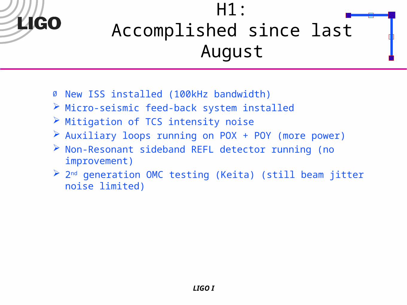
Ø New ISS installed (100kHz bandwidth) Micro-seismic feed-back system installed Mitigation of TCS intensity noise Auxiliary loops running on POX + POY (more power) Non-Resonant sideband REFL detector running (no improvement) 2nd generation OMC testing (Keita) (still beam jitter noise limited)

LIGO I
H2:Accomplished since last August
Ø All 4 AS photodiodes + electronics installed A whole series of small electronics modifications copied from H1. Auxiliary loop bandwidth increase TCS system installed (but H2 already was close to max recycling gain) Moderate power increase (1.4 Watts into the MC)
But sometimes the biggest sensitivity improvement steps come from eliminating goof-ups…
13
H1: Test mass replacement
H1: Test mass replacement
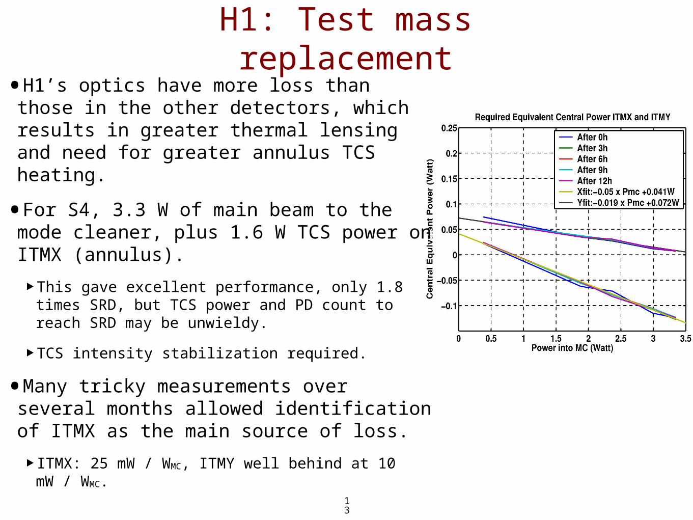
•H1’s optics have more loss than those in the other detectors, which results in greater thermal lensing and need for greater annulus TCS heating.
•For S4, 3.3 W of main beam to the mode cleaner, plus 1.6 W TCS power on ITMX (annulus).
‣This gave excellent performance, only 1.8 times SRD, but TCS power and PD count to reach SRD may be unwieldy.
‣TCS intensity stabilization required.
•Many tricky measurements over several months allowed identification of ITMX as the main source of loss.
‣ITMX: 25 mW / WMC, ITMY well behind at 10 mW / WMC.

14
L1 Progress: TCS, RF oscillator
L1 Progress: TCS, RF oscillator
•For S4, TCS power set to increase sideband recycling gain, without adding too much AS_I, even with its servo. This worked OK, and L1 was shot noise limited for 2 W to the modecleaner.
•After S4, it was discovered that higher power distorted some (non-core) optics enough that one of the WFS sensors was ineffective; the relevant telescope was reworked, the WFS system became effective again, the AS_1 servo was no longer required. We expect to need only very small TCS correction for S5.
•Crystal oscillator and improved RF distribution system installed during S4, which eliminated remaining phase noise effect in GW signal. Beat with other RF oscillator sometimes seen in signal, and will be finally eliminated by using fixed rational multiple for other RF, when custom hardware arrives.

15
L1 progress: sensing and control
L1 progress: sensing and control
•ITMX pick-off beam now used to sample recycling cavity light. This stronger beam allows higher SNR in auxiliary DOF servos.
•Higher loop gains in WFS loops.
•Higher loop gain ‘tidal’ servo, overlaps lower end of HEPI band, stabilizes interferometer during sub-tenth-hertz motion.
•Mitigation of scattering from output tables reduced parasitic interferometry that was due to relative velocity between seismically-isolated in-vacuum components and external optics tables.
•Non resonant REFL detection chain.

16
L1 Progress: ElectronicsL1 Progress: Electronics
•Electronics moved to “CDS highbay” in (mostly) RF-tight racks, reducing acoustic coupling and RF interference.
•All CDS equipment runs on “balanced power,” which should reduce line harmonic content.
•Modified LSC photodetectors to notch out 2nd harmonic of RF sideband.
•Increased number of Photodiodes from 2 to 4 for S4, then back to 2 after WFS telescope repair was made.
•New AS_I servo electronics for S4, not (always) needed now.

17
Other post-S4 thingsOther post-S4 things
•New laser for L1, then another new laser for L1
‣Two lasers currently at Lightwave for rework, so that work gets done before Lightwave’s move to new headquarters. We have one non-optimal spare at the moment.
•Work at Caltech to prepare for test mass swap.
•Work at MIT & LLO on tweaks to HAM HEPI control.
•Production of new photodiodes and other RF electronics
•Optical-fiber timing system (should cure channel hoping), New processor code (should cure mad slider disease).
•Acoustic coupling studies and repair at LHO.