1. leg 78b: background, objectives, and geological setting1 · leg 78b: background, objectives, and...
TRANSCRIPT

1. LEG 78B: BACKGROUND, OBJECTIVES, AND GEOLOGICAL SETTING1
Matthew H. Salisbury, Deep Sea Drilling Project, Scripps Institution of Oceanographyand
Roy D. Hyndman, Pacific Geoscience Centre, Department of Energy, Mines and Resources, Sidney, B. C.2
BACKGROUND AND OBJECTIVES
During the past several years, increased recognitionof the scientific potential of deep-sea boreholes as con-duits for conducting geophysical research in the crusthas led to greater emphasis on downhole measurementsand experiments by the Deep Sea Drilling Project. Theimportance of such experiments arises mainly from theneed to integrate data from a wide variety of sources—in-cluding downhole logs and experiments, geophysicaland geological site surveys, and studies of core materi-al—in order to understand the structure and physicalproperties of the crust.
Although the concept of an integrated program ofcoring followed by downhole measurements and experi-ments is relatively new, the Deep Sea Drilling Projecthas already gained considerable experience with individ-ual measurements and experiments. A limited downholelogging program was conducted on Legs 1 through 6,employing natural-gamma, gamma-density, neutron-po-rosity, and resistivity tools operated by personnel fromGrice Ocean Engineering, Schlumberger, and Dresser-Atlas. After a long hiatus, the logging program was re-newed in 1974 and has continued on many, although notall, cruises since that time, using personnel and equip-ment provided by Schlumberger and Gearhart-Owen. Thetools have included those listed above, plus sonic veloci-ty, temperature, and caliper logs. Although the qualityof the data has occasionally been excellent (e.g., Legs48, 61, 69, and 70; Montadert, Roberts, et al., 1979;Boyce, 1981; Cann and Von Herzen, 1983), many of thelogs have suffered from poor hole conditions, operation-al difficulties, and tool problems. In general, good logswere obtained only by persistence.
A limited heat-flow program has also been carriedout on the Glomar Challenger since the beginning of theproject to measure temperature and heat flow as a func-tion of depth in the sediment column and to monitortransient thermal phenomena. Although the importanceof such measurements is widely recognized and the toolshave gone through changes and developments, the num-ber of valid measurements remains small (see review byHyndman et al, this volume).
Hyndman, R. D., Salisbury, M. H., et al., Init. Repts. DSDP, 78B: Washington (U.S.Govt. Printing Office).
^ Addresses: (Salisbury) Deep Sea Drilling Project, Scripps Institution of Oceanography,La Jolla, CA 92093; (Hyndman) Pacific Geoscience Centre, Dept. of Energy, Mines and Re-sources, P.O. Box 6000, Sidney, B. C. V8L4B2, Canada.
With the expansion of the drilling program to includemajor basement or crustal objectives during the Inter-national Phase of Ocean Drilling (IPOD), several geo-physicists began to design downhole experiments forstudying the ocean crust and to deploy them from theChallenger. These included an oblique seismic experi-ment, in which a downhole seismometer is lowered andmonitored from the drill ship while a shot pattern is de-tonated from a second ship (successfully deployed onLegs 52, 65, and 70; Stephen et al., 1980, 1983; Stephen,1983); a long-term borehole-recording seismometer ex-periment designed to monitor natural seismicity and ex-plosions (successfully deployed on Leg 67; Aubouin, vonHuene, et al., 1982); a large-scale resistivity experimentdesigned to investigate the electrical resistivity of theformation beyond the zone invaded by drilling fluids(Legs 60 and 70; Francis, 1982; Von Herzen et al.,1983); and a combined downhole packer-televiewer ex-periment designed to measure permeability, fluid flow,pore pressure, and in situ stress in the crust (Leg 69; Zo-back and Anderson, 1983).
In general, these experiments have been conducted sep-arately on cruises having other primary objectives. Whenseveral of these experiments were very successfully com-bined with logging on Legs 51-53, 69, and 70 (Salisburyet al., 1980), it was realized that there would be consid-erable value in conducting cruises with logging anddownhole experiments, rather than coring, as the pri-mary objectives.
Leg 78B represents the first such cruise specificallydesigned and approved by the JOIDES advisory panelsfor downhole measurements. The original impetus forthe cruise arose from the scarcity of good downhole logsin the ocean crust. This was particularly critical in thefew deep crustal holes drilled, because the recovery insuch holes was poor and because the physical propertiesof the core material were clearly not representative ofthe large-scale properties of the crustal sections pene-trated. One of the deepest of these holes, and one of themost attractive candidates for re-entry (since it had beencased to basement) was Hole 395A on the Mid-AtlanticRidge (Fig. 1). The hole had been drilled on Leg 45 (Mel-son, Rabinowitz, et al., 1979a) to a sub-basement depthof 571 m in 7.2-Ma-old crust on the west side of theridge, south of the Kane Fracture Zone, as part of along-term program designed to determine the petrologi-cal, geochemical, and geophysical properties of the oceancrust and to determine the mechanisms by which it formsand evolves. Although the hole had been continuously
635

M. H. SALISBURY, R. D. HYNDMAN
45° N
1 S ' '
75°W 60° 45° 30° 15°
Figure 1. Location of Hole 395A. Dashed lines show age of the crust in Ma, deduced from magnetic anomalies.
cored and the recovered material extensively studied, nodownhole measurements had been made, and the core re-covery was poor. In consequence, many important fea-tures of the drilled section, such as its velocity structureand formation properties, remained obscure.
Detailed regional geophysical data from this area werealready available from the original site surveys carriedout before drilling (Hussong et al., 1979; Purdy et al.,1979; Kasahara et al., 1980; Rabinowitz and Ludwig,1980). These studies included detailed bathymetry, mag-netics, gravity, seismic reflection (including multichan-nel) profiling, seismic refraction data from ocean-bot-tom seismographs and sonobuoys, and several heat-flowmeasurements. At the same time, the stratigraphy of thehole and the petrology, geochemistry, and physical proper-ties of the rocks were known from studies of the coreand from the drilling record (Melson, Rabinowitz, et al.,1979b). Important results that still needed to be corrobo-rated and investigated in detail included a marked dis-parity in regional versus laboratory seismic velocities,which implies large-scale porosity; magnetic reversals inthe core, which may imply short-duration field reversalsor long-distance lava transport; and very low regionalheat-flow values, which may imply vigorous circulationand thus high permeability in the crust.
The primary objective of the Leg 78B scientific pro-gram was therefore to study the geophysical and hydro-geological properties of the upper oceanic crust at Site395 through downhole logging and downhole experiments,for comparison with previous studies of the core andwith regional geophysics. For a general understandingof the structure and physical properties of the crust and
of the processes affecting it, these measurements mustbe conducted at many scales of investigation. Site sur-vey data are needed to determine the regional propertiesof the crust; downhole measurements and experimentsare needed to provide information on a wide variety ofproperties under in situ conditions at a scale of investi-gation of a few meters; and laboratory measurementson core samples are needed to define the intrinsic behav-ior of the materials making up the crust. Although labora-tory measurements allow calibration of the downholelogs, they do not usually give results representative ofthe formation, because of the small size of the samplesstudied, because of serious core-recovery biases, and be-cause of the difficulty of simulating in situ conditions inthe laboratory. The differences, however, between labora-tory and logging results and between the results of log-ging and regional geophysical studies give important in-formation on the nature and extent of cracks, fissures,and other forms of large-scale porosity in the crust.
On Leg 78B, it was planned to use logging tools de-signed to measure the diameter of the hole, the tempera-ture of the water in the hole, and the sonic velocity, elec-trical resistivity, bulk density, porosity, and natural gam-ma radiation of the formation. Additional special downholetools included a borehole acoustic televiewer designed tooutline structures in the wall of the hole (such as pil-lows, flows, and fractures) and a downhole magnetome-ter/susceptibility meter designed to measure field varia-tions associated with differences in rock magnetizationdirection and intensity (particularly those associatedwith field reversals) and to measure differences in the in-trinsic magnetic properties of the rocks.
636

BACKGROUND, OBJECTIVES, AND GEOLOGICAL SETTING
The downhole experiment program was planned toinclude (1) a packer experiment for large-scale permea-bility tests, in situ pressure tests, large-volume water sam-pling, and hydrofracture tests; (2) a program to measurethe temperature and collect water samples down thehole using the self-contained heat-flow/pore-water sam-pler; (3) a large-scale resistivity experiment; and (4) theexperimental emplacement of a borehole seismometerdesigned by Teledyne Geotech, Inc. for the Defense Ad-vanced Research Projects Agency (DARPA) and the Na-val Ocean Research and Development Activity (NOR-DA). The seismometer emplacement was intended as atest of the procedures and equipment to be used duringthe emplacement of a semipermanent seismometer inthe floor of the North Pacific by the Glomar Challengerin 1982. It was also planned to have a second ship, theLynch, rendezvous at the site to assist in the deploymentby providing current-meter measurements and to deto-nate a pattern of shots to be recorded both by the down-hole seismometer and by an array of ocean-bottom seis-mographs deployed around the site. Thus, an activeseismic experiment similar to the oblique seismic experi-ments conducted on earlier legs was planned as part ofthe DARPA/NORDA test to complement the other ex-periments and logs conducted at the site.
GEOLOGICAL AND GEOPHYSICAL SETTING
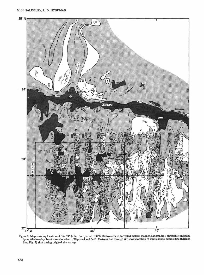
Site 395 is at 22°45' N, 46°05' W on the west flank ofthe Mid-Atlantic Ridge about 110 km west of the riftvalley and an equal distance south of the Kane FractureZone (Figs. 1 and 2). To the east, between the site andthe rift, lies the high plateau or crest range described byvan Andel and Bowin (1968) and characterized by rela-tively low relief and water depths of about 3 km.
The region in the vicinity of the site is characterizedby high relief (2400-4600 m water depths) with a crudetopographic lineation striking N10°E. In addition to aseries of regional surveys conducted in the area duringthe 1960s by the Lamont-Doherty Geological Observa-tory (Vema 2501 and 2503) and the Woods Hole Ocean-ographic Institution (Chain 44; van Andel and Bowin,1968), the area around the site was surveyed in detail in1974 by the Hawaii Institute of Geophysics (Kana Keoki74-01-09, Leg 7) as part of the IPOD site survey pro-gram, to select a site suitable for deep basement penetra-tion (Hussong et al., 1979; Purdy et al., 1979; Kasaharaet al., 1980). Also, Digicon, Inc. ran a multichannelseismic line (Fig. 3) over the site in 1974 to determinewhether sub-basement structures could be discerned inthe ocean basins using multichannel techniques. Thesesurveys indicate that sediments are present only in iso-lated ponds occupying topographic depressions (Figs.3A, 3B, and 4).
Site 395 itself is at the foot of a 1300-m scarp nearthe edge of one of the youngest and thickest of theseponds. As can be seen in Figure 5, the sediments rangeup to 0.3 s (2-way travel time) or 300 m in thickness inthe southeast portion of the pond. Like many of theseponds, this one shows evidence—in the form of offsetsin the sediments across minor faults—of fairly recenttectonic activity. The activity appears to have been lim-
ited, however, to the northeast limb, leaving the rest ofthe pond, including the area around the site, undisturbed.
From analyses of the magnetic anomalies mapped inthe area during the site survey program (Fig. 6), it is ap-parent that Site 395 lies within Anomaly 4 (Figs. 2 and5). Thus, the crust should have formed about 7.2 Maago (Fig. 7) at a half-spreading rate of 1.7 cm/y., andthe rocks should be normally polarized (Hussong et al.,1979; Purdy et al., 1979). It should be emphasized, how-ever, that the anomalies are quite variable throughoutthe area and are difficult to correlate. Although theanomalies, like the bathymetry, display a prominentgrain striking N10°E, offsets in the anomaly patternsuggest the presence of small fracture zones north andsouth of the site (Fig. 7). The more northerly of the twois also suggested by the bathymetry.
During the site survey conducted before drilling, anextensive series of heat-flow measurements was made inand around the site sediment pond to characterize thethermal regime of the site (Fig. 5). Excluding one mea-surement which appeared anomalously high (120 mW/m2), all the values fell within 4 mW/m2 of the site aver-age of 37 mW/m2. Although this average appears to below, given the age of the site, the uniformity of the mea-surements suggests that it accurately represents the heatflow in the pond. If this is so, the heat flow would ap-pear to be depressed by convection in the underlyingcrust.
In addition to bathymetric and magnetic surveying, asurvey of the gravity field was conducted in the area ofthe site. Although the gravity anomalies shown in Fig-ure 8 have not been modeled in detail, it is apparentfrom a comparison with Figure 4 that they are closelyrelated to bathymetry.
Finally, a detailed seismic refraction experiment wasconducted around the site (Fig. 9) before drilling to de-termine whether the velocity structure was typical of youngocean crust, and to provide a basis for comparison withthe drilling results (Hussong et al., 1979; Kasahara etal., 1980). As can be seen in Table 1 and Figure 10, thelayer thicknesses and velocities are highly variable through-out the region even after topographic corrections havebeen applied to the data: In general, the layers beneaththe sediment ponds are thinner and deeper and displayhigher velocities than equivalent layers beneath topo-graphic highs (Hussong et al., 1979). Similarly, thoughthe 3-layer model of Raitt (1963) is generally applicable,the high-velocity basal layer of Sutton et al. (1971) wasobserved on at least one of the lines (f in Fig. 10), andthe mantle was not observed on another (line d).
Despite these irregularities, however, Layer 2 was reli-ably detected and surprisingly uniform, at least in veloc-ity, on most lines (Vp ranges from 4.36 to 4.93 km/s,and the thickness ranges from 0.6 to 2.2 km). More par-ticularly, the velocity structure under the pond itself wasdetermined with some certainty because lines c and g(Fig. 10) had reverse refraction directions and could betreated as a single end-to-end reverse profile. The resultsof this treatment (Fig. 11) indicate that the boundarybetween Layers 2 and 3 is about 1.3 km below the mud-line, the Mohoroviòic discontinuity is remarkably shal-
637
M. H. SALISBURY, R. D. HYNDMAN
25 N i —
47° W
Figure 2. Map showing location of Site 395 (after Purdy et al., 1979). Bathymetry in corrected meters; magnetic anomalies 1 through 5 indicatedby mottled overlay. Inset shows location of Figures 4 and 6-10. Eastwest line through site shows location of multichannel seismic line (Digiconline; Fig. 3) shot during original site surveys.
638

Figure 3. A-D. Dip-filtered multichannel seismic reflection profile (Digicon line) shot along E-W profile over Site 395 by Gulf Seal, November, 1974. The profile shown extends from 46°45'W tothe east side of the rift valley at 44°54'W (solid line in Fig. 2). (SP = shot point; CDP = common depth point.)

B
1081 1101 1121 1141 1161 1181 1201 1221 1241 1261 1281 1301 1321 1341 1361 1381 1401 1421 1441 1461 1481 1501 15211541 1561 15811601 1621 1641 16611681 1701 1721 1741 1761 1781 1801 1821 1841 1861 1881 1901 1921 1941 1961 1981 2001 2021 COP
Figure 3. (Continued).
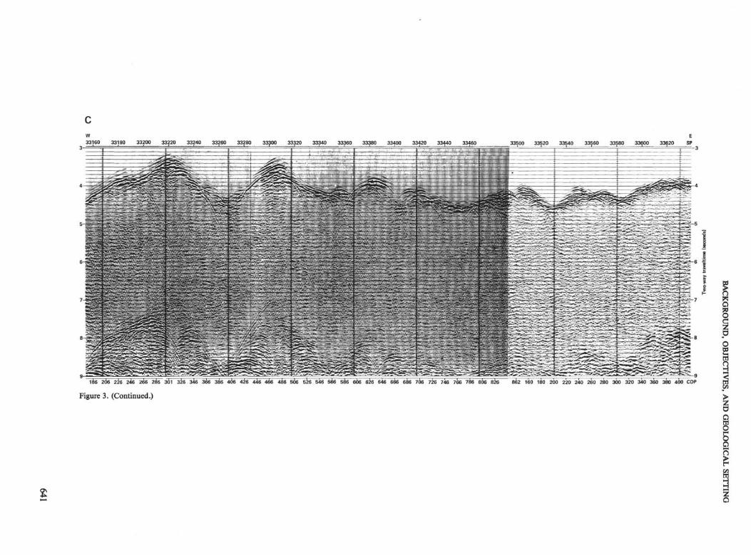
Figure 3. (Continued.)

Figure 3. (Continued.)
2X
gr
Ijo
öX
θ
2

BACKGROUND, OBJECTIVES, AND GEOLOGICAL SETTING
23°15'N
23° 00' -
22 45' -
46°45'W 46=30' 46° 15' 46° 00' 45° 45' 45° 30'
Figure 4. Detailed bathymetry (in corrected meters) in the vicinity of Site 395 (after Hussong et al., 1979). Stip-pled areas indicate sediment ponds. Inset shows location of Figure 5.
low—above 4 km sub-bottom—and the velocities of Lay-ers 2 and 3 and the mantle are 4.6, 6.4, and 8.2 km/s,respectively (Kasahara et al., 1979). It should be noted,however, that the relief on the steep (17°) scarp immedi-ately to the southeast of the site is comparable to orgreater than the depth to Layer 3, and that the apparentLayer-3 velocities shown in this direction (7.4 km/s online d in Fig. 10) are exceptionally high. If this scarp is afault scarp, it is possible that plutonic rocks are exposedat the surface. Although the Digicon line clarifies theshape of the sediment basin at Site 395 (Fig. 3B), nosub-basement structures suggesting such a relationshipwere observed.
HOLE 395AHole 395A was drilled on Leg 45 to a sub-bottom
depth of 664 m, 571 m of which was in basement. Thehole took 31 days to drill (9 December 1975 to 9 Janu-ary 1976), including setting the re-entry cone and casingand making six bit changes.
The sediment section, which was cased, consists of 93m of Pleistocene to upper Miocene foraminiferal-nanno-fossil ooze interbedded with foraminiferal sands andlaced with turbidites containing fragments and shardsof basalt and serpentinite. This was underlain by 18 m
of rubble, presumably talus from the scarp to the south-east, composed of clasts and cobbles of basalt, gabbro,and serpentinite in an ooze matrix. The remainder ofthe section, from the base of the rubble to the bottom ofthe hole, consists of pillow basalts (509 m or 89% of thesection), intrusive dolerites (22 m; 4%), igneous breccias(40 m; 7%), and traces of serpentinite. No interbeddedsediments were recovered.
As can be seen in Table 2 and Figure 12 (Melson, Ra-binowitz, et al., 1979b; Natland, 1979), the basementsection can be divided into 23 lithologic units belongingto eight major chemical units plus a serpentinite brecciabelow the uppermost extrusive. The chemical units con-sist of three aphyric pillow basalt units (A2, A3, and A4)and five phyric units (P2, P3, P4, P 4 ' , and P5), of whichP2 is massive and P4 ' is the intrusive equivalent of P4.Each chemical unit (if P4 and P4 ' are taken together) ap-pears to represent a discrete episode of submarine vol-canism. On geochemical and magnetic grounds it ap-pears that few, if any, of these units are comagmatic orrelated to each other by fractionation, even though allare low-K tholeiites.
The uppermost unit, A2 (111-173 m sub-bottom), isthe least fractionated of the aphyric units. It is a nor-mally polarized pillow basalt with an average inclination
643

M. H. SALISBURY, R. D. HYNDMAN
22° 52'N
22° 42'
Table 1. Seismic refraction results near Site 395.
46°09'W 46°00'W
Figure 5. Detailed bathymetry (in corrected meters) and sediment iso-pach map (sediment thickness in tenths of a second two-way traveltime) in the immediate vicinity of Site 395 (after Purdy et al.,1979). Also shown are the boundaries of magnetic Anomaly 4 andthe locations of heat-flow stations (sqares) and their values (in pa-rentheses) discussed in the text.
of +38°, which is consistent with the expected inclina-tion for the site ( + 40°) and the observed polarity ofAnomaly 4. The inclination and intensity of magnetiza-tion are extremely regular, suggesting that the entire62-m thick unit was extruded within less than 100 yrs.
Immediately beneath Unit A2 is an 8-m-thick brecciacomposed of basalt and serpentinite clasts. The unit isequivalent to a more complex breccia found at an equiv-alent sub-basement depth in Hole 395, and is thought torepresent a talus deposit similar to the rubble overlyingUnit A2.
The next four units (181-362 m sub-bottom) consistof phyric basalt. The uppermost, Unit P2, is a 29-m-thick unit of plagioclase-olivine phyric basalt. The onlymassive extrusive unit in the section, it is normally po-larized (+ 20 to + 40°), and is the most evolved of thephyric basalts. The remaining three phyric units, P3, P4,and P5, are 50, 48, and 54 m thick, respectively, andconsist of plagioclase-olivine ± clinopyroxene phyric pil-low basalts with glassy selvages throughout and brecciasnear the base of the sequence. Unit P3 is normally po-larized ( + 40 to +50°), but P4 and P5 are reversely po-larized (-38 and -40°, respectively). The top of Unit P4is more weathered than the base of P3, and no transi-tional orientations were observed between the two, sug-gesting a hiatus between eruptions longer than a typicalmagnetic polarity transition. Units P3, P4, and P5 aresuccessively more evolved with depth, with P3 the mostprimitive phyric basalt in the section.
The next unit, A3 (362-570 m sub-bottom), is a 208-m-thick reversely polarized (-43°) aphyric pillow basalt
Receivers
4
33
23
OBSI2
OBSI5
11678
OBSI9
OBSI11
33
1213
OBSIOBSI
66
141412123
15
1215
3123
16
OBSIOBSI
2
3.78
4.54
4.61
4.864.76
3.65
3.914.654.35
4.75
4.53
3.79
4.533.84
4.56
4.72
4.393.23
4.40
3.49
3.66
3.503.50
4.46
4.41
Note: Data taken2-4 = Layers.
3Velocitie!(km/s)
6.46
6.53
6.60
6.856.78
5.95
6.427.045.93
6.91
6.63
6.52
7.116.16
6.70
6.79
6.564.90
6.82
6.39
6.46
6.887.27
6.44
5.95
45
7.43
7.91
7.71
7.647.87
7.91
7.45
8.53
8.30
8.39
7.80
6.12
6.87
6.87
8.09
8.08
from Hussong
Waterdepth(km)
3.51
3.953.93
4.113.76
4.623.954.693.99
3.383.253.962.662.70
4.644.38
4.713.76
4.073.943.993.81
4.574.64
3.953.673.12
4.46
3.52
4.123.49
4.274.193.903.40
4.664.73
2 3Thickness
1.37
1.441.57
1.321.89
0.981.800.841.17
0.901.481.731.681.93
0.561.19
0.671.18
1.461.741.591.23
0.981.02
0.911.790.42
1.38
0.74
1.680.89
1.311.351.721.83
0.920.89
et al. (1979).
(km)
1.77
2.52
2.18
2.602.83
1.44
2.544.14
1.595.3O(?)
2.862.63
2.87
3.361.783.67
2.50
2.26
3.81
3.70
2.33
2.302.31
Numbers
with breccias at the top and again at about two-thirds ofthe way down the unit. Starting about midway throughthis unit (476 m) and continuing to the base of the hole,the section becomes increasingly annealed by low-tem-perature vein fillings composed of clay, carbonate, zeo-lites, and traces of opal. Also starting in this unit andcontinuing intermittently to the bottom of the hole wasa marked tendency for the more coherent cores to self-destruct into numerous fragments after recovery. Whetherthis was a result of stress relief or the expansion under
644

BACKGROUND, OBJECTIVES, AND GEOLOGICAL SETTING
23°15'N
23° 00' -
22° 45'
22° 30' -
22° 15' -
22° 00'46°45'W 46° 30' 46° 15' 46° 00' 45° 45' 45° 30'
Figure 6. Residual magnetic anomaly map in the vicinity of Site 395 (from Hussong et al., 1979). Total magneticfield intensity shown in gammas after correction for 1965 International Geomagnetic Reference Field.
decompression, of gas, water, or clay in cracks is un-known. The phenomenon was particularly striking in Lith-ologic Units 18, 21, and 23, and was also observed atabout the same depth in Hole 418A.
The deepest aphyric unit (A4; 570-616 and 633-671m sub-bottom), consists of an annealed pillow basaltcut by an intrusive dolerite (P4 ' ; 616-633 m) and inter-laced with altered breccias. The unit can be distinguishedfrom A3 by a subtle change in chemistry and an abruptchange to normal polarity (+ 50 to +60° above the in-trusive). The dolerite is reversely polarized ( - 40°) andchemically indistinguishable from Unit P4, which sug-gests that it is its intrusive equivalent. Below the intru-sive, the pillow basalts of Unit A4 have been hydrother-mally altered, causing the intensity of magnetization todecrease and the inclination to become irregular ( - 60°to + 30°) to the base of the hole.
Although the units defined here have been describedwith an air of certainty (for more detail, the reader is re-ferred to Volume 45 in its entirety: Melson, Rabinowitz,et al., 1979a), it must be borne in mind that the recoveryin Hole 395A averaged only 19%. As pointed out by theLeg 45 scientific party (Melson, Rabinowitz, et al., 1979b),the recovery varied with lithology, the aphyric pillow ba-
salts giving the lowest average recovery (8 and 7% for A2and Lithologic Unit 16 of A3, respectively), the phyricpillow basalts a higher recovery (13% for Units P3, P4,and P5), and the massive basalts a much higher recovery(32% for Unit P2). Near the base of the hole, where thesection has become massive by virtue of annealing, therecovery was high regardless of lithology (19% in theaphyric basalts of Lithologic Units 18 and 19; 40% inthe intrusive dolerites of Unit P4 ' ; 37% in the aphyricbasalts of Lithologic Unit 23). Given the low overall re-covery, however, and the fact that large sections of thehole were drilled with less than 5% recovery, the unitboundaries must be considered tenuous, and it is likelythat several thin units were missed entirely—which, ofcourse, was one of our reasons for logging the hole onLeg 78B.
REFERENCES
Aubouin, J., von Huene, R., et al., 1982. Site 494: Middle AmericaTrench lower slope. In Aubouin, J., von Huene, R., et al., Init.Repts. DSDP, 67: Washington (U.S. Govt. Printing Office), 27-78.
Boyce, R. E., 1981. Electrical resistivity, sound velocity, thermal con-ductivity, density-porosity, and temperature obtained by labora-tory techniques and well logs: Site 462 in the Nauru Basin of thePacific Ocean. In Larson, R. L., Schlanger, S. O., et al., Init.Repts. DSDP, 61: Washington (U.S. Govt. Printing Office), 743-762.
645
M. H. SALISBURY, R. D. HYNDMAN
Cann, J. R., and Von Herzen, R. P., 1983. Downhole logging at DeepSea Drilling Project Sites 501, 504 and 505, near the Costa RicaRift. In Cann, J. R., Langseth, M. G., Honnorez, J., Von Herzen,R. P., White, S. M., et al., Init. Repts. DSDP, 69: Washington(U.S. Govt. Printing Office), 281-300.
Francis, T. J. G., 1982. Large-scale resistivity experiment at Deep SeaDrilling Project Hole 459B. In Hussong, D. M., Uyeda, S., et al.,Init. Repts. DSDP, 60: Washington (U.S. Govt. Printing Office),841-852.
Hussong, D. M., Fryer, P. B., luthill, J. D. and Wipperman, L. K.,1979. The geological and geophysical setting near DSDP Site 395,North Atlantic Ocean. In Melson, W. G., Rabinowitz, P. D., et al.,Init. Repts. DSDP, 45: Washington (U.S. Govt. Printing Office),23-37.
Kasahara, J., Hussong, D. M., and Sutton, G. H., 1980. A seismicstudy using ocean-bottom seismometers near the Mid-Atlantic Ridgeat 23°N. Mar. Geol., 35:199-218.
Melson, W. G., Rabinowitz, P. D., et al., 1979a. Init. Repts. DSDP,45: Washington (U.S. Govt. Printing Office).
, 1979b. Site 395: 23°N, Mid-Atlantic ridge, In Melson, W.G., Rabinowitz, P. D., et al., Init. Repts. DSDP, 45: Washington(U.S. Govt. Printing Office), 131-264.
Montadert, L., Roberts, D. G., et al., 1979. Site 402/Hole 402A. InMontadert, L., Roberts, D. G., et al., Init. Repts. DSDP, 48:Washington (U.S. Govt. Printing Office), 125-164.
Natland, J. H., 1979. Comparison of chemical and magnetic stratigra-phy of DSDP Sites 332 and 395. In Melson, W. G., Rabinowitz, P.D., et al., Init. Repts. DSDP, 45: Washington (U.S. Govt. PrintingOffice), 657-677.
Purdy, G. M., Rabinowitz, P. D., and Schouten, H., 1979. The Mid-Atlantic Ridge at 23°N: Bathymetry and magnetics. In Melson, W.G., Rabinowitz, P. D., et al., Init. Repts. DSDP, 45: Washington(U.S. Govt. Printing Office), 119-128.
Rabinowitz, P. D., and Ludwig, W. J., 1980. Geophysical measure-ments at candidate drill sites along an east-west flow line in thecentral Atlantic Ocean. Mar. Geol., 35:243-275.
Raitt, R. W., 1963. The crustal rocks. In Hill, M. N. (Ed.), The Sea(Vol. 3): New York (Wiley), 85-102.
Salisbury, M. H., Stephen, R., Christensen, N. I., Francheteau, J.,Hamano, Y., Hobart, M., and Johnson, D., 1980. The physical
state of Cretaceous oceanic crust from the results of logging, labo-ratory studies, and the oblique seismic experiment at Deep SeaDrilling Project Sites 417 and 418. In Donnelly, T., Francheteau,J., Bryan, W., Robinson, P., Flower, M., Salisbury, M., et al., Init.Repts. DSDP, 51, 52, 53, Pt. 2: Washington (U.S. Govt. PrintingOffice), 1579-1597.
Stephen, R. A., 1983. The oblique seismic experiment on DSDP Leg70. In Cann, J. R., Langseth, M. G., Honnorez, J., Von Herzen,R. P., White, S. M., et al., Init. Repts. DSDP, 70: Washington(U.S. Govt. Printing Office), 301-308.
Stephen, R. A., Johnson, S., and Lewis, B., 1983. The oblique seis-mic experiment on Deep Sea Drilling Project Leg 65. In Lewis, B.T. R., Robinson, P. T., et al., Init. Repts. DSDP, 65: Washington(U.S. Govt. Printing Office), 319-328.
Stephen, R. A., Louden, K. E., and Matthews, D. H., 1980. Theoblique seismic experiment on Deep Sea Drilling Project Leg 52.In Donnelly, T. W., Francheteau, J., Bryan, W., Robinson, P. T,Flower, M., Salisbury, M., et al., Init. Repts. DSDP, 51, 52, 53,Pt. 1: Washington (U.S. Govt. Printing Office), 675-704.
Sutton, G. H., Maynard, G. L., and Hussong, D. M., 1971. Wide-spread occurrence of a high velocity basal layer in the Pacific foundwith repetitive sources and sonobuoys. In Heacock J., (Ed.), Phys-ical Properties of the Oceanic Crust, Am. Geophys. Union Monogr.,14:193-210.
van Andel, T. H., and Bowin, C. O., 1968. Mid-Atlantic Ridge be-tween 22° and 23° north latitude and the tectonics of mid-oceanrises. J. Geophys. Res., 73:1279-1298.
Von Herzen, R. P., Francis, T. J. G., and Becker, K., 1983. In sitularge-scale electrical resistivity of ocean crust, Hole 504B. In Cann, J.R., Langseth, M. G., Honnorez, J., Von Herzen, R. P., White, S.M., et al., Init. Repts. DSDP, 69: Washington (U.S. Govt. Print-ing Office), 237-244.
Zoback, M. D., and Anderson, R. N., 1983. Permeability, underpres-sures, and convection in the oceanic crust at Deep Sea DrillingProject Hole 504B. In Cann, J. R., Langseth, M. G., Honnorez,J., Von Herzen, R. P., White, S. M., et al., Init. Repts. DSDP, 69:Washington (U.S. Govt. Printing Office), 245-254.
Date of Initial Receipt: September 20, 1983Date of Acceptance: October 5, 1983
646

BACKGROUND, OBJECTIVES, AND GEOLOGICAL SETTING
23°30'N
23° 15' -
23° 00' -
22°45' -
46°45'W 46° 30' 46° 15' 46° 00' 45° 45' 45° 30' 45° 15'
Figure 7. Magnetic anomalies and isochrons in the vicinity of Site 395 (from Hussong et al., 1979). Solid lines show tentativelocations of fracture zones. Ages shown in Ma.
647

M. H. SALISBURY, R. D. HYNDMAN
23°15'N
23° 00'
22°45'
22° 30'
22° 15'
22°00'46°45'W 46° 30' 46° 15' 46° 00' 45° 45' 45° 30'
Figure 8. Free-air anomaly map in the vicinity of Site 395 (from Hussong et al., 1979). Values shown in milligals.
648

BACKGROUND, OBJECTIVES, AND GEOLOGICAL SETTING
23°15'N
23° 00' -
22° 45' -
22° 30' -
22° 15' -
22° 00'46° 45' W 46° 30' 46° 15' 46° 00' 45° 45' 45° 30'
Figure 9. Refraction lines run during site survey in the vicinity of Site 395 (from Hussong et al., 1979). Sonobuoylocations are numbered 1 through 16; of the three ocean-bottom seismometers (I—III) deployed, only OBS Ifunctioned properly.
649

M. H. SALISBURY, R. D. HYNDMAN
23°15'N
23° 00' -
22°45' -
22°30' -
22°15' -
22°00'46°45' W 46° 30' 46° 15' 46u00' 45°45' 45° 30'
Figure 10. Crustal velocity models obtained along shot lines shown in Figure 9 (from Kasahara et al., 1980). Veloci-ties in km/s. Small numbers indicate sub-bottom depths in km.
650

BACKGROUND, OBJECTIVES, AND GEOLOGICAL SETTING
Drill site _
0 -
Layer3
(1.3)-6
- 8
-(4)
Velocities in km/sVertical exaggeration 2:1
Figure 11. Seismic velocity structure in the vicinity of Site 395 (after Hussong et al., 1979; Kasahara et al.1980). Numbers in parentheses represent depths sub-bottom.
Table 2. Lithologic summary, Hole 395A.a
Seds.
Layer2
- 2
- 4
- T D
Lithologic Chemicalunit unit Lithology Cores
Inferred sub-bottominterval (m) and
thickness (in paren.) Distinguishing characteristics
Sedimentary breccia 3-5
23456
789
10
1112
13
14
151617
18
19
2021
22
23
?4
P5
A3
A4
P 4 .
A4
Aphyric basaltSedimentary brecciaPhyric basaltPhyric basaltPhyric basalt
Phyric basaltPhyric basaltPhyric basaltPhyric basalt
Phyric basaltPhyric basalt
Basaltic breccia
Phyric basalt
HyaloclastiteAphyric basaltBasaltic breccia
Aphyric basalt
Glass-rich basalticbreccia andaphyric basalt
Dolerite
Aphyric basalt
Dolerite
Aphyric basalt withsome glassy brec-cia zones
5-131313-1617-2222
23-2526-272829
3031
32
33
3333-4949
49-58
58-61
61
62
62-64
64-67 +
87.60-110.79(23.19)
110.79-172.44(61.65)172.44-174.31 (1.87)174.31-210.52(36.11)210.52-257.00 (46.48)257.00-260.37 (3.37)
260.37-288.79 (28.42)288.79-307.84 (19.05)307.84-317.34 (9.50)317.34-326.87 (9.53)
326.87-336.06(9.19)336.06-344.46 (8.40)
344.46-354.00 (9.54)
354.00-360.87 (6.87)
360.87-362.24(1.37)362.24-504.77 (142.53)504.77-508.74 (3.97)
508.74-585.00 (76.26)
585.00-608.10(23.10)
608.10-617.49(9.39)
617.49-617.96 (0.47)
617.96-630.15 (12.19)
630.15-664.09+ (33.94 + )
Sub-rounded to angular fragments of aphyric basalt, and ultramafic tomafic plutonic rocks in foraminifer-nannofossil ooze
Aphyric pillow basaltTwo sub-angular fragments of serpentinite, 1 pc. aphyric basaltPlagioclase-olivine phyric fine-grained massive basaltPlagioclase-olivine-clinopyroxene phyricPlagioclase-olivine-clinopyroxene phyric with fewer plagioclase pheno-
crysts than Unit 5Plagioclase-olivine phyric with rare large clinopyroxene phenocrystsPlagioclase-olivine clinopyroxene phyricPlagioclase-olivine phyricPlagioclase-olivine-clinopyroxene phyric pieces and plagioclase-olivine
phyric piecesOlivine-plagioclase phyricMixed pieces plagioclase-olivine-clinopyroxene phyric and plagioclase-
olivine phyricAngular clasts of fine- to medium-grained plagioclase-olivine phyric basalt
in carbonate clay-rich matrix; clasts include coarsest-grained basaltfound; evidence of hydrothermal alteration
Mixed pieces plagioclase-olivine-clinopyroxene and plagioclase-olivinephyric basalt
Fine-grained basalt and basaltic glass in recrystallized carbonate oozeAphyric basalt with very rare rounded plagioclase "xenocrysts"Angular, brecciated fine- to medium-grained basalt clasts, including
variolitic rinds and altered glass clasts in clay-rich matrixAphyric basalt with rare olivine and plagioclase "xenocrysts," highly
fractured, abundant veins filled with secondary mineralsBreccias with abundant basaltic glass marginally altered to numerous
secondary minerals in a matrix of alteration products; some zones ofaphyric basalt with some glassy rinds with variolitic zones
Plagioclase-olivine-clinopyroxene basalt, medium-grained
Thin zone of aphyric basalt with glassy and variolitic rind; surfacessheared and coated with clay and other secondary minerals
Plagioclase-olivine-clinopyroxene basalt, medium-grained; quenched con-tact at base
Aphyric basalt, glassy basaltic breccias, numerous glassy-variolitic rinds,abundant soft light-colored clay in fractures; highly fractured
a Note: Taken from Melson, Rabinowitz, et al. (1979b).b The boundary between Chemical Units A3 and A4 lies within Lithologic Unit 18 at a sub-bottom depth of 570.08 m.
651

M. H. SALISBURY, R. D. HYNDMAN
~jy-rTyj Serpentinizedperidotite
D D D
D α
a x ax D x
mm
Fbraminifer—nannofossil ooze
Aphyric
pillow lavas
Flows
Breccias
Ol-plagphyric
01—plag-cpxphyric
Pillow lavas
Flows
Breccias
4700-
4 8 0 0
5 0 0 0 -
Lithology £ gn n
D D D D
_ Crack (generalized)**" with surrounding
alteration
5149-
o .2 E S |ö ε ç .E S
4 P-
16 A3
LBre
19 Largelybreccia
p;
23 A*
-100
+38
Cobbles
+20 to+40
+40 to+50
38
-40
-43
+50 to+60
-40
Hydro-thermal lyaltered
-60 to +3C
-200
-300
-400
-500
r-βoo
Figure 12. Basement stratigraphy in Hole 395A (after Melson, Rabinowitz, et al., 1979b).
652