1 internetworking outline best effort service model global addressing scheme
Post on 20-Dec-2015
213 views
TRANSCRIPT

1
Internetworking
Outline Best Effort Service ModelGlobal Addressing Scheme

2
IP Internet
• Concatenation of Networks
• Protocol Stack
R2
R1
H4
H5
H3H2H1
Network 2 (Ethernet)
Network 1 (Ethernet)
H6
Network 3 (FDDI)
Network 4(point-to-point)
H7 R3 H8
R1
ETH FDDI
IPIP
ETH
TCP R2
FDDI PPP
IP
R3
PPP ETH
IP
H1
IP
ETH
TCP
H8

3
Service Model• Connectionless (datagram-based)• Best-effort delivery (unreliable service)
– packets are lost– packets are delivered out of order– duplicate copies of a packet are delivered– packets can be delayed for a long time
• Datagram formatVersion HLen TOS Length
Ident Flags Offset
TTL Protocol Checksum
SourceAddr
DestinationAddr
Options (variable) Pad(variable)
0 4 8 16 19 31
Data
4
Fragmentation and Reassembly
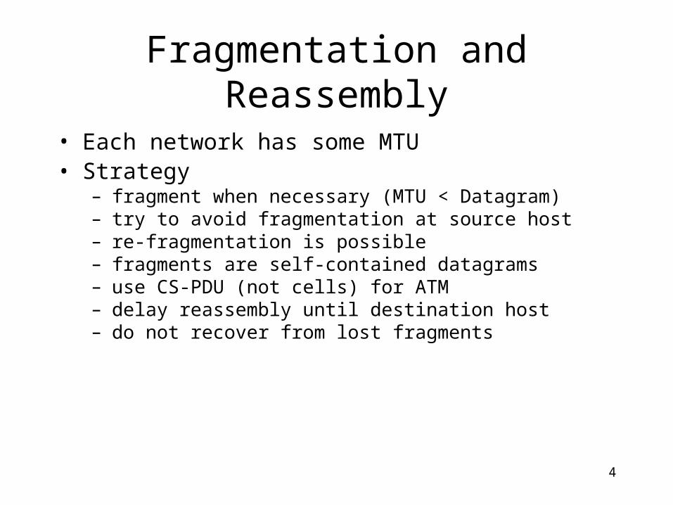
• Each network has some MTU• Strategy
– fragment when necessary (MTU < Datagram)– try to avoid fragmentation at source host– re-fragmentation is possible – fragments are self-contained datagrams– use CS-PDU (not cells) for ATM– delay reassembly until destination host– do not recover from lost fragments

5
Example
H1 R1 R2 R3 H8
ETH IP (1400) FDDI IP (1400) PPP IP (512)
PPP IP (376)
PPP IP (512)
ETH IP (512)
ETH IP (376)
ETH IP (512)
Ident = x Offset = 0
Start of header
0
Rest of header
1400 data bytes
Ident = x Offset = 0
Start of header
1
Rest of header
512 data bytes
Ident = x Offset = 512
Start of header
1
Rest of header
512 data bytes
Ident = x Offset = 1024
Start of header
0
Rest of header
376 data bytes

6
Global Addresses
• Properties– globally unique– hierarchical: network + host
• Dot Notation– 10.3.2.4– 128.96.33.81– 192.12.69.77
Network Host
7 24
0A:
Network Host
14 16
1 0B:
Network Host
21 8
1 1 0C:

7
Datagram Forwarding • Strategy
– every datagram contains destination’s address– if directly connected to destination network, then forward to host– if not directly connected to destination network, then forward to
some router– forwarding table maps network number into next hop– each host has a default router– each router maintains a forwarding table
• Example (R2) Network Number Next Hop 1 R3 2 R1 3 interface 1 4 interface 0

8
Address Translation • Map IP addresses into physical addresses
– destination host– next hop router
• Techniques– encode physical address in host part of IP address– table-based
• ARP– table of IP to physical address bindings– broadcast request if IP address not in table– target machine responds with its physical address– table entries are discarded if not refreshed
9
ARP Details
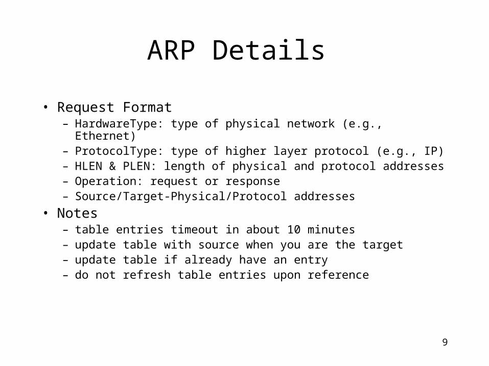
• Request Format– HardwareType: type of physical network (e.g., Ethernet)– ProtocolType: type of higher layer protocol (e.g., IP)– HLEN & PLEN: length of physical and protocol addresses– Operation: request or response – Source/Target-Physical/Protocol addresses
• Notes– table entries timeout in about 10 minutes– update table with source when you are the target – update table if already have an entry– do not refresh table entries upon reference

10
ARP Packet Format
TargetHardwareAddr (bytes 2 – 5)
TargetProtocolAddr (bytes 0 – 3)
SourceProtocolAddr (bytes 2 – 3)
Hardware type = 1 ProtocolType = 0x0800
SourceHardwareAddr (bytes 4 – 5)
TargetHardwareAddr (bytes 0 – 1)
SourceProtocolAddr (bytes 0 – 1)
HLen = 48 PLen = 32 Operation
SourceHardwareAddr (bytes 0 – 3)
0 8 16 31

11
Error ReportingInternet Control Message Protocol (ICMP)
12
Dynamic Host Configuration Protocol (DHCP)
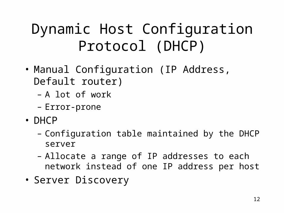
• Manual Configuration (IP Address, Default router)– A lot of work
– Error-prone
• DHCP– Configuration table maintained by the DHCP server
– Allocate a range of IP addresses to each network instead of one IP address per host
• Server Discovery

13
IP header,Destination = 2.x
IP payload
IP header,Destination = 10.0.0.1
IP header,Destination = 2.x
IP payload
IP header,Destination = 2.x
IP payload
Network 1 R1 Internetwork Network 2R2
10.0.0.1
Tunneling
14
Virtual Private Networks
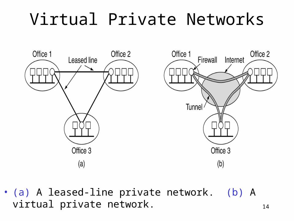
• (a) A leased-line private network. (b) A virtual private network.