1 interfacing user input devices joystickstrackballsmouses touch screen light pens x-y digitizer...
TRANSCRIPT

1
Interfacing User Input DevicesInterfacing User Input Devices
JoysticksJoysticks
TrackballsTrackballs
MousesMouses
Touch ScreenTouch Screen
Light PensLight Pens
X-Y DigitizerX-Y Digitizer
Digital CameraDigital Camera
Chap 0 2
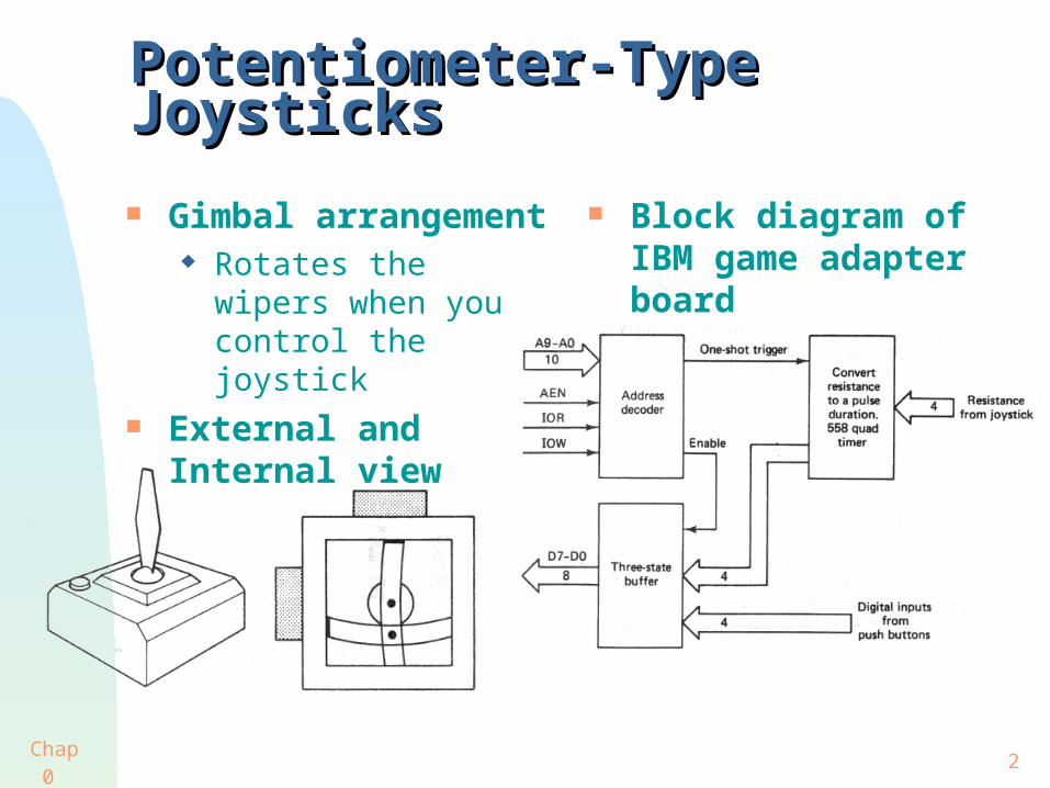
Potentiometer-Type JoysticksPotentiometer-Type Joysticks
Gimbal arrangement Rotates the wipers
when you control the joystick
External and Internal view
Block diagram of IBM game adapter board

Chap 0 3
Potentiometer-Type JoysticksPotentiometer-Type Joysticks
Game adaptor board In expansion slot Address of 201H
Converting resistance into digital value 558 Quad timer
Resistance to Pulse duration
Permit use of two simultaneous joysticks
Duration = 24.2 + 0.011(R) (s)
OUT command to port 201H All four one-shots are
fired IBM PC convert duration
to digital number using clock and register
IN command to port 201H Reads the values of four
one shot output Status of each of the fire
button

Chap 0 4
Potentiometer-Type JoysticksPotentiometer-Type Joysticks Two joystick can
be connected to the IBM PC
IN command returns 1 Byte
information STICK command
in BASIC returns X and Y
coordinates of sticks

Chap 0 5
Build custom designed prototype Build custom designed prototype boardboard
For connecting a potentiometer type and switch type joysticks
Port address = 309H OUT to 309H
/BIOW and /E9 Triggers 556 dual timer
IN at 309H /BIOR and /E9 Pulse duration and Fire
button to be read through 74LS244

Chap 0 6
Build custom designed prototype Build custom designed prototype boardboard
Reading duration BASIC is too slow to read pulse duration
Assembly Language Program is preferred Trigger one shot and then continuously read
the port until both one shot timed out Polling
Use 8253 programmable timer to get more accurate result
Interrupt or Polling See Section 3.3, For more information

Chap 0 7
Alternative Approach Using ADCAlternative Approach Using ADC
ADC0816 on Prototype board For more information,
See Chapter 5
BASIC program to read digital value from each channel
Homework #11-1 Analyze this program

Chap 0 8
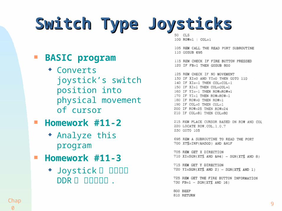
Switch Type JoysticksSwitch Type Joysticks
Four switches
Standard 9-Pin
Connect to Prototype board Buffer input values for
all possible switch positions
Two switches can be ON if the stick is moved diagonally
Chap 0 9
Switch Type JoysticksSwitch Type Joysticks
BASIC program Converts joystick’s
switch position into physical movement of cursor
Homework #11-2 Analyze this program
Homework #11-3 Joystick 을 변형하여
DDR 을 구성해보라 .

Chap 0 10
TrackballsTrackballs
Control device Movement of ball
causes optical encoders to generate pulse
Speed Direction of rotation
Most trackball produce 50 ~ 550 pulses per
revolution TTL level signal
x , -x, y, -y The photodiodes in the
optical encoder are placed such that the encoder detect the proper left or right (up and down) movement 1 LED + 1 photodiode :
Speed only 2 LED + 2 photodiode :
Speed and Direction

Chap 0 11
Trackball InterfaceTrackball Interface
Two Up/Down Counter For x and y axes
Boundary Detection Logic Prevent roll over
From 255 to 0 From 0 to 255

Chap 0 12
MousesMouses
Hand-held digital input devices Lisa from Apple
computer 1st computer use
mouse to control applications
Upside down trackball Generate pulses using photo-
optical sensors and optical interrupt disk
IBM PC Interface RS-232C PS-2
Optical Mouse 2 LED inside mouse shine down
onto two-color grid of lines on a special board
Reflect back up through lens and are detected by 4-quadrant sensing device
Similar to Optical Bar Code Reader

Chap 0 13
Touch ScreensTouch Screens Resistive Touch
Screen From TSD Display
Products Output voltage is
proportional to the position touched
5 operating mode Inactive Continuous output Output on Initial touch only ADDS Regent 40
alignment Fixed array of 80 touch
screen

Chap 0 14
Touch ScreensTouch Screens
Using ultrasonic technique Piezoelectric transducer
Mounted along the edge of screen
Set up acoustic surface waves
The travel time of waves are constant unless finger disturb them
The x and y location of finger can be predicted by echo-ranging technique
Using capacitance sensing When a pad is touched
The body’s capacitance is added and sensed

Chap 0 15
HPTouchHPTouch
Adopted in HP 150 PC Optical touch screen
LED Along the bottom and
right side Photodiode
Along the top and left side
40 x 23 matrix of beams The rays are slightly
above the surface of screen
Actually touching screen is not necessary
Softkeys Functions keys
displayed on the bottom of the screen
Computer recognize a selection only when the finger is withdrawn

Chap 0 16
Light PensLight Pens
Raster Scan CRT
Cathode Ray Tube
Sawtooth waveform is applied to yoke
Simplified tracing
Video signal is sent to the Electron Gun
To ensure synchronization of raster scan Trigger pulses are sent
with video signal to mark the beginning of the sawtooth
Hsync for Horizontal Vsync for Vertical

Chap 0 17
Light PensLight Pens
Raster Scan TV
Hsync = 15,750Hz Vsync = 60Hz
IBM Monochrome monitor Hsync = 18,432Hz Vsync = 50Hz
Interlace Mode High resolution graphic
monitor and in TV Allows the image to be
updated twice as often Yet, keeps the BW of
system the same Raster scan is not traveling
twice as fast
Composite video signal Decode by monitor

Chap 0 18
Light PensLight Pens
Detects light emitted by the phosphor screen When tip detects light, it
sends a signal to the processor
Phototransistor is preferred Higher sensitivity Response is slower than
photodiode Produced current from
photo-detector Convert to voltage Amplified High pass filtered
• Remove 60Hz and sunlight
Possible decoding technique for the light pen
counter
counter
Light Pen
Hsync/N
몇 번째Hsync
Hsync/N 중몇 번째

Chap 0 19
X-Y DigitizersX-Y Digitizers
A device that sends to computer the coordinates of the location of a special pen on the tablet
Methods of Conversion Ultrasound
Pen emit ultrasound Sensors in the border of
tablet measure travel time
Location of pen can be calculated
Electromagnetic Tablet set up an
electromagnetic field which is disturbed by the pen in some predictable way
Magnetostrictive Screen like mesh is under
the tablet surface Intersection of two wires
describes an x-y pair Pulses of current travel
along the wire, create magnetic fields
Pen detects moving magnetic filed and determine the coordinates

Chap 0 20
Homework #11-4Homework #11-4
최근 컴퓨터가 소형화 되면서 키보드를 대신할 입력 장치에 대한 관심이 높아지고 있다 . 특히 pen 을 이용하여 직접 입력하는 방법이 문자 인식 기술의 발전에 따라 PDA 등에서 많이 채용되고 있는 추세이다 . 이런 목적을 달성할 수 있는 입력장치를 고안해보라 .