1 i engineering data transmittal 617895
TRANSCRIPT

Page 1 of I 1 . ~ 0 ~ 617895 ENGINEERING DATA TRANSMITTAL
2. To: (Receiving Organization) 3. From: (Originating Organization) 4. Related EDT No.:
5. Proj./Prog./Dept./Div.: Distribution FFTF N/A
6. Design Authority/ Design Agent/Cog. Engr.: 7. Purchase Order No.:
101-SY Spare Mitigation Retrieval ~~i~~ G. ~~~~l in/Charles R. ~~~h N/A Mixer Pump 8. Originator Remarks: 9. Equip./Cornponent No.:
- 16. KEY
E, S, Q, D or N/A 1. Approval4. Review 1. Approved 4 . Reviewed no/comnent (see WHC-CM-3-5, 2. Release5. Post-Review 2. Approved wlcomnent5. Reviewed w/comnent Sec. 12.7) 3. Information6. Dist. (Receipt Acknow. 3. Disapproved wlcomnent6. Receipt acknowledged
17. SIGNATURE/DISTRIBUTION (See Approval Designator f o r required signatures)
Approva L Desi gnator (F) Reason f o r Transmittal ( G ) Disposit ion ( H ) & (I)
Required)
["CI Approved Design Authority/ Date w/comnents Cognizant Manager [^C1 Disapproved
w/comnents
ED-7400-1 72-1

;J H N f WW-SD-FF-EV-003, Rev. 0
TEST REPORT FOR THE RUN-IN ACCEPTANCE TESTING OF THE HYDROGEN MITIGATION RETRIEVAL PUMP-3
Brian G. Bergl in , Charles R. Nash B&W Hanford Company, Richland, WA 99352 U.S. Department o f Energy Contract DE-AC06-87RL10930
Org Code: B18220 Charge Code: h)z 2x5 B&R Code: E W 3 / 4 0 D 7 Z Total Pages: 48
Key Words: 101-SY, Primary, Backup, Mixer Pump, Mi t iga t ion , Retr ieval
Abs t rac t : Mi t iga t ion Retr ieval Pump-3. The pump was received and t e s t e d a t t h e 400 Area MASF Facil i t y .
EDT/ECN: 617895 UC: 2030
A r e p o r t on t h e r u n - i n acceptance t e s t i n g of the Hydrogen
TRADEMARK DISCLAIMER. trade name, trademark, manufacturer, or otherwise, does not necessari ly const i tu te o r imply i t s endorsement, recomnendation, or favoring by the United States Government o r any agency thereof or i t s contractors or subcontractors.
Reference herein t o any speci f ic comnercial product, process, o r service by
Pr inted i n the United States of America. To obtain copies of t h i s document, contact: WHC/SCS Document Control Services, P.O. Box 1970, Mailstop H6-08, Richland WA 99352, Phone (509) 372-2420; Fax (509) 376-4989.
I
r -1 Y-97 Release Approval 0 Date Release Stamp
Approved for Public Release
A-6400-073 (10/95) GEF321

HNF-SD-FF-EV-003 Rev. 0
TEST REPORT FOR RUN-IN ACCEPTANCE TESTING OF HYDROGEN MITIGATION RETRIEVAL PUMP-3
Prepared by Brian G. Berglin & Charles R. Nash
B&W Hanford Company Hanford Operations and Engineering Contractor
for the ’ U: S. Department of Energy
Richland Operations
TABLE OF CONTENTS
1.0 INTRODUCTION . . . . . . . . . . . . . . . . . . . . . . . . . . . . . . . . . . . . . . . . . . . . . Page1
2.0 PRE-OPERATIONAL CHECKS . . . . . . . . . . . . . . . . . . . . . . . . . . . . . . . . . . Page 2 2.1 Instrumentation . . . . . . . . . . . . . . . . . . . . . . . . . . . . . . . . . . . . . . . . . . . Page 2 2.2 BumpTest . . . . . . . . . . . . . . . . . . . . . . . . . . . . . . . . . . . . . . . . . . . . . . . Page2 2.3 Lifting the Pump to the Vertical Position Page 3
2.4.1 Total Indicated Runout (TIR) . . . . . . . . . . . . . . . . . . . . . . . . . . Page 3 2.4.2 Plumbness of pump . . . . . . . . . . . . . . . . . . . . . . . . . . . . . . . . . Page 3
2.4 Pump Alignment Checks . . . . . . . . . . . . . . . . . . . . . . . . . . . . . . . . . . . . Page 3
3.0 INSTALLATION . . . . . . . . . . . . . . . . . . . . . . . . . . . . . . . . . . . . . . . . . . . . . . Page 4 3.1 Insertion of Pump into the LDCV . . . . . . . . . . . . . . . . . . . Page4 3.2 Mini-DACS Setup and Operation . . . . . . . . . . . . . . . . . . . . . . . Page4 3.3 Rotating Mechanisms of the Pump . . . . . . . . . . . . . . . . . . . . . . . . . . . . Page 4
3.3.1 Rotation Drive Motor and Gear Box . . . . . . . . . . . . . . . . . . . . . Page 4 3.3.2 Upper Column Split Ring and Limit Switch 3.3.3 Electrical Turntable/Power Trak Assembly
3.4 Nitrogen Supply . . . . . . . . . . . . . . . . . . . . . . . . . . . . . . . Page5 3.5 Motor Stator Reserv . . . . . . . . . . . . . . . . . . . . . . . . . . . . Page5 3.6 Cooling Water to Heat Exchanger . . . . . . . . . . . . . . . . . . . . . . . . . . . . . Page 5 3.7 Jackscrews . . . . . . . . . . . . . . . . . . . . . . . . . . . . . . . . . . . . . . . . . . . . . . Page5 3.8 LDCV Water Level . . . . . . . . . . Page 6
4.0 TEST PLAN DEVIATIONS. . . . . . . . . . Page 6 4.1 Nitrogen Supply . . . . . . . . . . . . . . . Page 6 4.2 Rotational Drive Motor and Gear Box . . . . . . . . . . . . . . . . . . . . . Page6 4.3 TIR of Pump Alignment . . . . . . . . . . . . . . . . . . . . . . . . . . . . . . . . . . . . . Page 7 4.4 Oil Pump Discharge Pressure . . . . . . . . . . . . . . . . . . . . . . . . . . . . . . . . Page 7 4.5 Pump Casing Vibration . . . . . . . . . . . . . . . . . . . . . . . . . . . . . . . . . . . . . Page 7
5.0 TESTING . . . . . . . . . . . . . . . . . . . . . . . . . . . . . . . . . . . . . . . Page8 5.1 Initial Ramp Up . . . . . . . . . . . . . . . . . . . . . . . . . . Page8 5.2 72 Hour Test . . . . . . . Page 8
5.2.1 Oil Cooling System Operation (Enclosure #6) Page 8 5.2.2 Initial Results and Findings . . . . . . . . . . . . . . . . . . . Page9 5.2.3 Cooling Water Results and . . . . . . . . . . . . . . . . . . . . Page9 5.2.4 Current Draw on the Pump Motor . . . . . . . . . . . . . . . . . . . . . . . Page 9 5.2.5 Summary.. Page 10
6.0 POST TESTING . . . . . . . . . . . . . . . . . . . . . . . . . . . . . . . . . . . . PagelO 6.1 Shear Pin Testing . . . . . . . . . . . . . . . . . . . . . . . . . . . . . . . . PagelO
. . . . . . . . . . . . . . . . . . . . . . . . . . . . . . . . . .
6.2 Oil System Pressure . . . . . . . . . . . . . . . . . . . . . . . . . . PagelO
Page 10 7.0 CORRECTIVE ACTIONS . . . . . . . . . . . . . . . . . . . . . . . . .

7.1 Moisture Alarm . . . . . . . . . . . . . . . . . . . . . . . . . . . . . . . . . . . . . . . . . . . Page 10 7.2 Electrical TurntablelPower Trak . . . . . . . . . . . . . . . . . . . . . . . . . . . . . Page 11 7.3 Instrument Repairs . . . . . . . . . . . . . . . . . . . . . . . . . . . . . . . . . . . . . . . Page 11 7.4 Leaks in the Pump Column and Motor Shroud . . . . . . . . . . . . . . . . . . Page 11 7.5 Instrument Tubing on Lower End of Pump . . . . . . . . . . . . . . . . . . . . . Page 12 7.6 Carbon Steel Parts below the Mounting Plate . . . . . . . . . . . . . . . . . . . Page 12 7.7 New Valve added on Oil System to Assist in Draining Motor Oil . . . . . Page 12
8.0 STORAGE . . . . . . . . . . . . . . . . . . . . . . . . . . . . . . . . . . . . . . . . . . . . . . . . . Page12
9.0 REFERENCES . . . . . . . . . . . . . . . . . . . . . . . . . . . . . . . . . . . . . . . . . . . . . . Page 13 9.1 Workpackages . . . . . . . . . . . . . . . . . . . . . . . . . . . . . . . . . . . . . . . . . . Page13 9.2 Engineering Change Notices . . . . . . . . . . . . . . . . . . . . . . . . . . . . . . . . Page 13
10.0 ENCLOSURES . . . . . . . . . . . . . . . . . . . . . . . . . . . . . . . . . . . . . . . . . . . Page 13
11.0 PHOTOS . . . . . . . . . . . . . . . . . . . . . . . . . . . . . . . . . . . . . . . . . . . . . . . . Page14
12.0 MASF PUMP TEST PERSONNEL Page 14
iii

HNF-SD-FF-EV-003 Rev. 0
1 .O INTRODUCTION
This report will provide the findings of the demonstration test conducted on the Double-Shell Tank (DST) 241-SY-101 HMR Pump-3 in accordance with WHC-SD-
MITIGATIONIRETRIEVAL PUMP-3" at the 400 Area Maintenance and Storage '
Facility (MASF) building from 7 June 1996 through 30 July 1996 per work package
WM-TP-434 "TEST PLAN FOR RUN-IN ACCEPTANCE TESTING OF HYDROGEN
4A-96-92Nv.
The DST 241-SY-101 Hydrogen Mitigation Retrieval (HMR) Pump-3 is a 200-HP submersible electric driven pump that has been modified for use in the DST 241-SY- 101 containing mixed waste located in the 200W area The pump has a motor driven rotation mechanism that allows the pump column to rotate through 355".
Prior to operation, pre-operational checks were performed which included loop calibration grooming and alignment (CGW) of instruments, learning how plumb HMR-3 assembly hung in a vertical position and bump test of the motor to determine rotation direction.
The pump was tested in the MASF Large Diameter Cleaning Vessel (LDCV) with process water at controlled temperatures and levels. In addition, the water temperature of the cooling water to the motor oil heat exchanger was recorded during testing.
A 480-volt source powered a Variable Frequency Drive (VFD). The VFD powered the pump at various frequencies and voltages to control speed and power output of the pump. A second VFD powered the oil cooling pump. A third VFD was not available to operate the rotational drive motor during the 72 hour test, so it was demonstrated as operational before and after the test.
A Mini Acquisition and Control System (Mini Dacs) controls pump functions and monitoring of the pump parameters. The Mini-DACS consists of three computers, software and some Programmable Logic Controllers (PLC). Startup and shutdown of either the pump motor or the oil cooling pump can be accomplished by the Mini- DACS. When the pump was in operation, the Mini-DACS monitors automatically collects data electronically. However, some required data from ancillary systems was collected manually and recorded on log sheets. Automatic and manual data acquisition was collected as shown in Enclosure #I.
If a parameter exceeds pre-established limits, an alarm is sounded at the Mini- DACS console. If the parameter is in the abort range the pump is automatically shutdown by the system. Actual data points taken from the test although available are not provided in this report, since this would result in an unnecessary large
Page 1

.~... HNF-SD-FF-EV-003 I Rev. 0
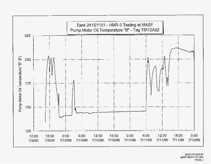
volume of information. Mini-DACS recorded parameters every six seconds during the test. However, some graphs of the oil temperature and pressure verses time from the Mini-DACS data during the 72 hour test will be provided (Enclosure #7). The MASF facility instrumentation was recorded and manually logged throughout the duration of the test at specific intervals (Enclosure #2).
2.0 PRE-OPERATIONAL CHECKS
Prior to installing the pump in the LDCV, the pump was positioned horizontal on the floor of MASF to perform a bump test to learn direction of rotation and check instrument loops to verify accuracy and alardabort set points. Two items were completed before the installation of the pump began: 1) instrument loop checks to verify accuracy, alarm and abort set points and 2) the pump was "bump" tested to detect direction of rotation. Following these, the pump was transferred to the vertical position to perform pump alignment checks.
2.1 Instrumentation
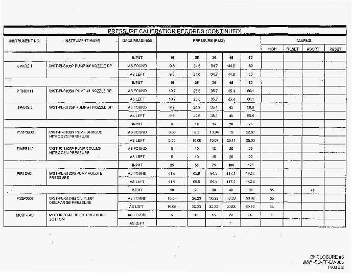
The pump was received with the instrument wiring not terminated in Junction Box (JBX)-1 . This was agreed upon between the TWRS Cognizant Engineer and the MASF Pump Project Manager prior to shipment of the pump to the 400 Area. Wiring for all instruments was prepped, labeled and landed per H-14- I00380 Sheets 1 and 2. Each wire was terminated using crimped ferrules to help ease of removal and termination as required for testing. Each instrument was checked and calibrated as required per the loop calibration procedures in the work package. Results of the loop calibration records are included in Enclosure #3.
The Pump Volute Pressure, WST-PE-3123M, was within the 2 psig tolerance at the low end of the scale but off by nearly 3 psi at the upper range. The instrument is not adjustable and is physically sealed to prevent nitrogen leaks. As there are not alarms or aborts associated with this instrument the consensus from TWRS Engineering was to accept the conditions listed AS IS.
The Oil Pump Discharge Pressure, WST-PI-3104M and the Pump Casing Vibration (Accelerometer), WST-VE-3127P could not be calibrated within tolerance's specified in the test plan. The test plan deviations for these instruments are discussed in Section 4.
2.2 Bump Test
Electrical connections were made from the VFD to JBX-3 oft$ pump while the pump was on the floor of MASF. The bump test was done and the direction of rotation was recorded in the work package. The rotation was counterclockwise (as
Page 2

HNF-SD-FF-EV-003 Rev. 0
looking from the top of the bump) with the terminationsas indicated. When the pump was connected to electrical power after the pump had been installed in the LDCV, the forward direction for the rotation on the VFD was reversed to make FORWARD the clockwise rotation of the pump.
2.3 Lifting the Pump to the Vertical Position
The pump was horizontally lifted up with the lower portion installed into the new "clamp and tilt fixture" as shown in Photo #I. The clamp and tilt fixture clamps to the bottom of the pump. The clamp is connected to a tilt fixture assembly vertically supported at the bottom four corners with roller skid dollies that will roll on the existing railroad tracks in the MASF high bay area. This allowed the pump to be
. lifted by the overhead crane from the horizontal position to the vertical position without horizontally moving the overhead crane as shown in Photo #2. The pump was designed to withstand the stresses induced from this lifting process therefore eliminating the need for a strongback and a mobile crane in addition to the MASF overhead crane. Following, the pump was removed from the clamp and tilt fixture as shown in Photo #3 in preparation for the pump alignment checks.
.. '
2.4 Pump Alignment Checks
2.4. I
2.4.2
Total Indicated Runout (TIR)
With the pump suspended freely in the vertical position from the overhead crane, the TIR and the side to side measurement of the pump shaft were recorded. TWRS Engineering established a limit of ,003" TIR and side to side. The side to side measurement was ,002". Using a calibrated dial indicator, the TIR measured ,0045" exceeding the ,003" limit. The TIR deviation was accepted by TWRS Engineering as explained in Section 4.
Plumbness of pump
Kaiser surveyors checked the plumb alignment of the pump in both the NorthlSouth and WedEast directions from the Barrel Assembly Flange to the Flush Ring. The pump was 5/16'' out of plumb in the east direction when measured in the NorthlSouth direction and 5/8" (.625") out of plumb when measured in the EasWest direction as shown in Enclosure #4. The largest pump diameter of 40.9' is at the 13" tall pump barrier fluid reservoir at the lower portion of the pump. The DST riser for pump insertion into the tank is 41.5" translating to a .6' distance before reaching interference. As noted above, the 40.9" diameter of the pump is only for a short distance, therefore since the out of plumbness for the pump is ,925" which is >.6'. During insertion, the pump must be lowered into the riser slightly off center
,
Page 3

HNF-SD-FF-EV-003 Rev. 0 SAP -
to eliminate any interference until the barrier fluid reservoir is past the bottom of the tank riser.
3.0 INSTALLATION
3.1 Insertion of Pump into the LDCV
Just before insertion, the pump barrier fluid reservoir was filled with approximately 5% gallons of Chevron GST-32 turbine oil. The pump installation into the LDCV was completed using the approved Critical Lift Procedure "INSTALLING THE SY-
FACILITY". The recorded weight of the pump 16,100 Ibs. which includes the .weight of the lifting yoke (1660 Ibs.), load cell (~501bs) and a shackle (161bs). Approximately 300 ft-lbs of torque was used to bolt the pump to the pump stand.
101 MIXER PUMP-3 ASSEMBLY FROM THE LDCV IN THE MASF PUMP TEST
3.2 Mini-DACS Setup and Operation
The Mini-DACS was connected and configured by a Mini-DACS specialist contract worker. Most pump functions and monitoring of pump parameters are controlled by the Mini-DACS (See Enclosure #I). The Mini-DACS is currently programmed to prevent the mixer pump from rotating during operation. The Rotating Drive Motor could not be operated even if it was connected to the separate VFD. This deviation from the Statement of Work requirement to rotate the Mixer Pump during the Initial Ramp Up and the Seventy-Two Hour Full-Speed Continuous Run-In is explained in Section 4. The Separate VFD was connected to the Cooling Oil Pump Motor for operation during Initial Ramp Up and the Seventy-Two Hour Full-Speed Continuous Run-In test periods.
3.3 Rotating Mechanisms of the Pump
3.3.1 Rotation Drive Motor and Gear Box
The rotation motor and gear box were bolted into place. Following, the gear drive, rotational motor mounting plates, and the drive shaft were installed using a 3/8" shear pin. The rotation motor and gear box were connected to the 5 hp VFD and verified operational. Speeds of pump rotation were checked and adjusted in preparation for testing the limit switches.
3.3.2 Upper Column Split Ring and Limit Switch
The limit switch was tested in both the clockwise and qunter clockwise direction and verified operational. During testing, it was found that the amount of drift that the pump rotates after the limit switch is tripped must be
Page 4

H N F-S D-FF-EV-003 Rev. 0
limited to keep the limit switches from being damaged. The VFD was adjusted to a low drift limit and tested satisfactorily. This limit of the VFD may be extracted from the Mini-DACS data. A 2" round tube stub protruding from the side of the pump, used for future tank waste transfers, nearly interfered with the upper column split ring during installation. The split ring triggers the limit switch which is mounted on the test stand about 3' lower than the expected field installation height. Therefore, field installation interferences are not expected.
3.3.3 Electrical Turntable/Power Trak Assembly
The electrical turntablelpower trak assembly is a new feature for this third generation mixer pump. It allows the use of standard cabling for connecting electrical power and instruments between fixed and rotating junction boxes. Close observation of the turntable in operation revealed several binding points that prevented full 355" rotation as shown in Photos #4 & #5. A video was made of the sequence of events.
3.4
3.5
3.6
Nitrogen Supply
The nitrogen supply from compressed gas bottles was connected to the pump. But, due to the significant leaks in the mixer pump, it became necessary to substitute instrument air throughout the test. It was decided that the most efficient manner necessary to complete this test was to perform the operational test, then fix the leaks following the test. Section 4 for explanation of this deviation from the test plan.
Motor Stator Reservoir
See
The motor stator reservoir was initially filled with 27 gallons of Shell Hyperia S220 oil as directed by the oil fill procedure, but oil was not observed in the storage tank site glass. An additional 6 gallons was added until the level was visible at mid level of the site glass.
Cooling Water to Heat Exchanger
Flexible hoses were installed from the MASF supplied cooling water to the oillwater heat exchanger with a 0-20 GPM flow meter on the inlet line and a 0-250°F temperature gauge on the outlet side. Long hoses were used so the pump could rotate while providing cooling water to the oil/water heat exchanger.
Page 5

HNF-SD-FF-EV-003 Rev. 0
3.7 Jack Screws
The screw jacks were turned out to fit the brake shoes tight against the DST mock-up riser wall. This prevents pump lateral movement within the 42" riser during operation. The average torque value for screw jack deployment was 25 ft-lbs with the final torque averaging 27.5 ft-lbs after the brake shoes made contact with the mock-up riser wall.
3.8 LDCV Water Level
The water level in the LDCV was filled to 31 '-6" over the cenerline of the horizontal discharge nozzle (36' level in the LDCV). The LDCV Water Level Control Panel was activated to alarm test personnel when the water level deviates f 1 foot from the 36' level. Enclosure #2 is a record of the LDCV water level throughout the 72 hour pump test.
4.0 TEST PLAN DEVIATIONS
The following deviations from the test plan requirements were accepted by the Pump Design Cognizant Engineer prior to testing the pump:
4.1 Nitrogen Supply
Reauirement Supply a dry nitrogen source to initially fill the pump system and pressurize up to 25 psig, then maintain between 21 and 25 psig during pump startup and operation with an expected leak rate < .4 ft3/hour. Discussion The leak rate was > .4 ft3/hour because of a known leak from the shroud air space through some electrical penetrations. This leak rate made it uneconomical to supply nitrogen from K bottles which were used up at the rate of one every 6 hours. Deviation Pressurized instrument air was used in lieu of nitrogen throughout the test.
4.2 Rotational Drive Motor and Gear Box
Reauirement. 1. Initial Ramp Up
Following data recording at the first speed setting, the rotation motor will be started and operated to turn the mixer pump through one complete
Page 6

HNF-SD-FF-EV-003 Rev. 0 d-
rotational cycle (forward and backward approximately 170" of travel each direction). The rotational motor will require manual operation from the VFD (pending) while the mixer pump is in operation.
2. Seventy-two Hour Full-Speed Continuous Run-In . During each shift, the rotational drive motor will be operated to advance the turntable through an angle of +170". As the 350" position is reached, the rotational drive will be reversed to continue the cycle. The 340" field of rotation is defined from orientations I O " to 350".
.
Discussion The Mini-DACS is currently programmed to prevent the Rotational Drive Motor from operating during Mixer Pump Operation. In addition, the Oil Cooling Motor Pump
separate source of power and VFD was available at MASF. Deviation 1. Initial Ramp Up
. " , and the Rotational Gear Drive require separate power sources and only one
The Rotational Gear Drive was operated before the Initial Ramp Up testing period as authorized by TWRS Cognizant Engineer.
The Rotational Drive Motor was operated before the 72 hour Full-Speed Continuous Run-In test period as authorized by the TWRS Cognizant Engineer.
2. Seventy-two Hour Full-Speed Continuous Run-In
4.3 TIR of Pump Alignment
Reauirement TIR and side to side limit of .003" with the pump hanging in the vertical position. Discussion Measurement of the TIR was ,0045" exceeding the established limit by TWRS Engiheering by .0015". Evaluations were discussed as to what damage could occur to the pump with a TIR exceeding the established limit.
The TWRS Cognizant Engineer accepted the TI,R of the pump shaft at ,0045" and authorized us to proceed Miith testing of the Mixer Pump.
. . Deviation
. 8;
4.4 Oil Pump Discharge Pressure
The Oil Pump Discharge Pressure, WST-PE-3104M, was out of tolerance over the entire range. Attempts to adjust the zero and scale were unsuccessful. As this instrument did have an alarm, the software was adjusted to match the alarm point to the input.
Y
Page 7

HNF-SD-FF-EV-003 -3.-
Rev. 0
4.5 Pump Casing Vibration
The Pump Casing Vibration (Accelerometer) WST-VE-3127P, was unresponsive to inputs. (Tapping on the pump with a hammer, no calibration points) It was noted throughout the test the readings from this element remained the same (0.1 gk). After the pump had been removed from the LDCV the loop was checked again. The loop was responsive, but the element was dead. Ohmmeter readings on the element were 1.7 megohms.
5.0 TESTING
5.1 Initial Ramp Up
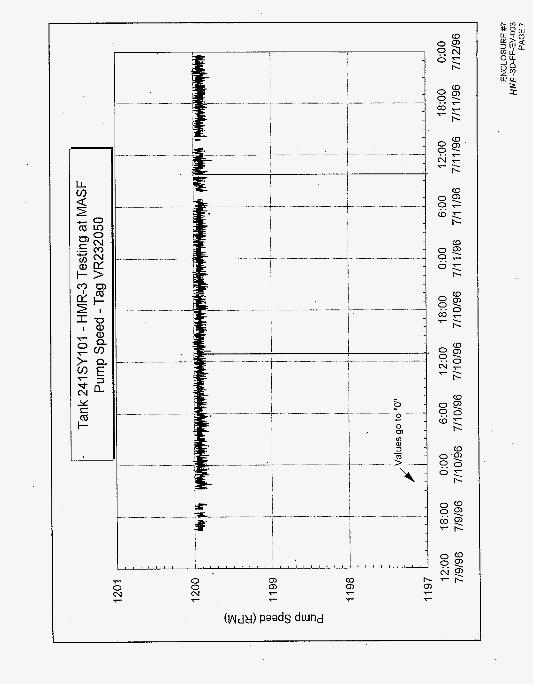
Initial Ramp up of the pump commenced on 07-08-96 at 600 RPMs with an LDCV tank temperature of 78.9 degrees. Ramp up consisted of raising the speed of the pump up 200 RPM's approximately every 15 minutes to ensure that all mechanical and electrical/l&C systems were operating correctly. The initial ramp up performed as expected with a duration of 46 minutes to reach 1200 RPMs. The Rotational Drive Motor operational test requirement was not performed during ramp up as described in Section 4.
5.2 72 Hour Test
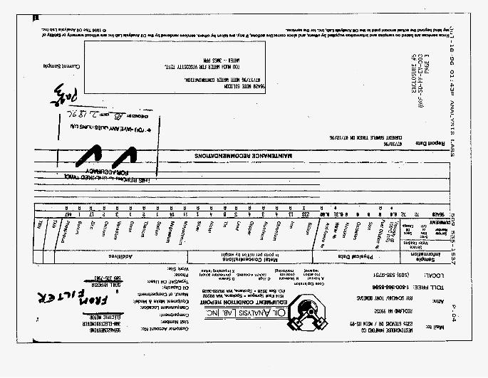
Approximately seven hours into the 72 hour run the pump shutdown on an ABORT signal from' the moisture alarm WST-ME3113M. The alarm immediately cleared itself. The pump was restarted and twice more aborted on moisture within a two hour period. The test was secured for approximately two hours for evaluation by Engineering. Restarting of the pump with oil cooling in continuous operation . appeared to alleviate the problem. During the remaining 72 hours of testing, several additional aborts were received because of the moisture element. Parameters of the oil cooling system were changed, but little success was recognized. The frequency of the alarms was random and could not be related to any specific condition of pump-operation. During the last sixteen b u r s of the test, TWRS engineering authorized us to override the moisture alarm and allow continuous operation of the pump. This decision was based upon an oil sample taken during the test showing a moisture content of approximately 3% (Enclosure #5). Recommend software changes be made to eliminate spurious alarms. No further action was taken during the test. The Rotational Drive Motor operational test requirement was not performed during the 72 hour Test as described in Section 4. - _ .
. -,"
Page 8

HNF-SD-FF-EV-003 REV 0
5.2.1 Oil Cooling System Operation (Enclosure #6)
The pump oil heat exchanger/cooling system was tested under Engineering direction. Various water and oil flows were tested to determine the maximum and minimum heat removal capabilities and pressure differentials of the system. After testing was complete, the system was allowed to run at varying predetermined cooling water flows.
5.2.2 Initial Results and Findings
The mixer pump was allowed to operate without oil circulation until the temperature of the LDCV water rose above 100°F. The cooling water was established through the oil/water heat exchanger at 11 GPM. Following, the oil pump was started by the VFD at 200 RPM and accelerated in 200-300 RPM increments up to 1800 RPM every 3-5 minutes. In addition, the Motor Oil Pressure (PN2PO507) and Motor Oil Pressure Stator Bottom (MOPSTAB) were recorded during ramp up. The MOPSTAB is located at the bottom of the pump case downstream of the annular gap between the rotor and stator while the PN2P0507 is located near the oil vent valve above the heat exchanger on the discharge of the oil pump. (See Enclosure #6.) The static pressure drop between PN2P0507 and MOPSTAB is 14 psig. With the oil pump motor operating at 1800 RPM, the AP between PN2P0507 and MOPSTAB was 1.22 psig which correlates directly to the pressure drop across the gap between the rotor and stator. This pressure drop was considered negligible and produced results significantly better than expected.
5.2.3 Cooling Water Results and Findings
Throughout the test the cooling water flow was varied from 11 GPM down to 5 GPM with the LDCV water temperature at approximately 120°F. At 5 GPM, the AT of the cooling rose to 13"F, whereas it remained at a constant 10°F AT between 8 and 11 GPM. Near the end of the test, the cooling water was shut off with just the oil pump operating. Since water was used for the test medium in the LDCV, the actual viscosity of the waste medium in the SY-101 tank is a lot higher, therefore the pump did not obtain a full load test during the testing period simulating actual field conditions. This resulted in a low AT across the oillcooling water heat exchanger on the cooling water side.
Page 9

HNF-SD-FF-EV-003 Rev. 0 -j-.--
5.2.4 Current Draw on the Pump Motor
Concerns were raised during the test regarding the current draw on the motor. Even though the values were within the range considered normal for this size pump, the values seen during this test were at least 10% higher than when the pump was tested at Hazleton. Further evaluation by TWRS engineering and the MASF Test engineer revealed several factors that could affect the current readings: use of the VFD, variances on the VFD current readings, longer cable leads to the motor making the pump a bigger load, and differences in the load itself. No further action was deemed necessary.
5.2.5 Summary
The testing of 101-SY Backup Pump was considered successful with the below noted discrepancies and actions taken. Oil analysis reports are provided as shown in Enclosure #6 Actual data points taken from the test although available are not provided in this report, as this would have resulted in a large physical volume of information. (Mini-DACS recorded sensor inputs every six seconds when actual testing was ongoing.) Select graphs were generated from the Mini-DACS data on oil temperatures and pressures verses time (72 hour test) and are provided per Enclosure #7. In addition, some graphs showing pump speed and amps verses time are also included. The graphs in Enclosure #7 are configured from data averaged over 1 minute intervals from the Mini-DACS.
6.0 POST TESTING
6.1 Shear Pin Testing
The shear pin test on the pump rotational system was performed by torquing it until it sheared at 540 ft-lbs.
6.2 Oil System Pressure Test
The oil system was pressure tested with N, at 20 psi with the heat exchanger removed (Photo #6). The allowable leak rate acceptable by TWRS Cognizant Engineer is <.5 psilhour. After 72 hours, the pressure dropped to 15 psi which results in a ,06944 psi/hr leak rate. The heat exchanger was then installed.and another decay pressure test was performed at 20 psi for 1 hour 17 minute. Pressure maintained 20 psi throughout the test. Therefore, the pressure leak test on the oil system was successfully passed with the system req$ning in tact.
Page 10

HNF-SD-FF-EV-003 REV 0
7.0 CORRECTIVE ACTIONS
7.1 Moisture Alarm
Additional bench testing of the moisture alarm circuit failed to reveal a functional problem with the circuit. Several oil samples with various concentrations of water were tested with alarms occurring as expected. The circuit did not appear extremely sensitive as theorized. To correct the problem, a separate set of moisture elements were installed upstream of the oil cooling pump and are in direct contact with the motor oil flowing through the system.
,
7.2 Electrical Turntable/Power Trak
There are several causes for the mechanical binding of the Power Trak. Larger sliding feet to bridge the stationary and rotational components of the system are necessary and a mechanical means to prevent the Power Trak from doubling on itself is needed. The small adjustments needed to make the power trak operate successfully will be accomplished per 4A-96-273AN.
7.3 Instrument Repairs
The oil pump discharge pressure element (WST-ME3113M) must be replaced. The pump volute pressure element (WST-PE-3123P) and the accelerometer (WST-VE-3127P) also need replacing. However, engineering should perform an evaluation to determine the need and accuracy of the pump volute pressure element and accelerometer.
Leaks in the Pump Column and Motor Shroud
After the testing had been completed, the pump was removed from the LDCV and stationed in MASF to allow work on the leaks. During the repair portion of this testing, it was discovered that the column leaked very little into the motor shroud. A pressure test showed that leakage was less than the spec and so the column leaks were considered satisfactory.
Work on the motor shroud began immediately after the pump was removed from the LDCV and positioned back to the horizontal position. Several attempts to fill the leaks with caulking material (glyptol) were unsuccessful. Leaks were occurring in the conduit and possibly through the power and instrumentation cables. To resolve the problem a junction box was installed in both the power and instrumentation circuits. All of the circuits were rewired through terminal boxes to provide a break in the routes assumed to be leaking. The terminal boxes were then filled with potting material to provide an additional barrier against leaks as shown in
7.4
Page 11

HNF-SD-FF-EV-003 " Z - Rev. 0
Photo #7. Following, the electrical terminal box assembly lid was installed and the instrument wiring connected as shown in Photo #8.
The pump column was pressure tested and verified to be leak tight. The motor shroud was leak tested a variety of ways. First, it was pressurized to 28 psi with N,. The allowable leakage as directed by TWRS Cognizant Engineer is <.7psi/hour. The pressure in the motor shroud decreased to 25 psi within 1 hour, 5 minutes resulting in a leakage 2.8 psi/hour. The pressure was bleeding over into the oil system. Therefore, the second test was done with the oil system at 20 psi and the motor shroud at 28 psi. During a 12-hour test, the shroud pressure dropped to 20.6 psi resulting in an ,616 psilhour pressure drop while the pressure on the oil system increased proportionally.
In conclusion, the oil system and the pump column that are on both sides of the shroud have successfully passed independent pressure tests. The motor shroud leaks into the oil system but the oil system does not leak into the motor shroud. Since the motor shroud is between the oil system and the pump column, no leakage will be loss to the atmosphere. Therefore, with concurrence from TWRS Cognizant Engineer, the motor shroud leakage to the oil system was acceptable since the independent pressure test of the oil system and pump column do not leak.
7.5 Instrument Tubing on Lower End of Pump
The instrument tubing needs securing on the lower end of pump. Some stainless steel hose clamps were installed around the instrument tubing cluster for the test with no apparent damage evident during the 72-hour test. However, prior to use in DST 241-SY-101, it is strongly recommended that additional permanent tubing . supports be installed to secure the tubing from possible damage and probable loss of pertinent data.
7.6 Carbon Steel Parts below the Mounting Plate
All the Carbon steel below the mounting plate rusted from the 120°F temperature of the LDCV water condensing. If the pump was operated for a very long period in DST 241-SY-101 tank with the screw jacks out against the inside of the riser, it is possible that they could rust into place and be very difficult if not impossible to retract the screw jacks for removal.
7.7 New Valve added on Oil System to Assist in Draining Motor Oil
While draining oil from the motor, it became necessary to remove the heat exchanger so the system could be pressurized to remove the'of. An isolation valve was installed between the oil pump and the heat exchanger so the oil can be
Page 12

HNF-SD-FF-EV-003 Rev. 0
changed without removing the heat exchanger as shown on the Oil System Diagram on page 1 of Enclosure #6.
8.0 STORAGE
The pump was loaded onto a trailer provided by TWRS per 4A-96-288Nv on 12-04- 96. Transfer of the pump to the 200 Area for permanent storage occurred on 12- 05-96.
9.0 REFERENCES
9.1 Work Packages
9.1 .I 9.1.2 9.1.3
4A-96-092NV - Test 101SY Hydrogen Mitigation Pump #3 in LDCV 4A-96-273NV - Complete 101SY HMR Pump 3 Cable Track Assembly 4A-96-288NV - J3, Load SY-101 #3 Onto Truck For Ship To Stor
9.2 Engineering Change Notices
9.2.1 9.2.2 9.2.3 9.2.4
9.2.5
9.2.6
ECN 631714 - Prevented nitrogen leaks from the shroud air space ECN 629121 -Wire the moisture sensor added to the oil cooling system ECN 6291 19 - Preventing nitrogen leaks from the shroud air space ECN 628794 - Replace disabled moisture sensor and change wiring diagrams ECN 628793 - Motor oil change-out changes and provides moisture sensitive capability ECN 628792 - Changes to WHC-SD-WM-TP-434 to allow usage of dry air instead of nitrogen.
10.0 ENCLOSURES
# I Automatic (Mini-DACS) and Manual (MASF Facility) Data Acquisition (1 page)
#2 Manual Pump Test Logs (4 pages)
#3 Loop Calibration Records (2 pages)
#4 Vertical Plumbness (1 page)
#5 Motor Oil Analysis Report (6 pages)
#6 Oil System Diagrams (2 pages)
Page 13

HNF-SD-FF-EV-003 Rev. 0
#7 Various (Oil PressurelOil TemperaturelMotor VoltagelMotor CurrenVPump Speed) verses Time (72 hour test) Graphs from Mini-DACS Data (8 pages)
11.0 PHOTOS
# I BOTTOM OF PUMP SITTING IN THE CLAMP &TILT FIXTURE HORIZONTALLY
#2 TRANSFERRING PUMP FROM THE HORIZONTAL TO THE VERTICAL POSITION
#3 VERTICAL PUMP REMOVAL FROM THE CLAMP &TILT FIXTURE
#4 ENTIRE ELECTRICAL TURNTABLElPOWER TRAK BINDING
#5 CLOSEUP OF ELECTRICAL TURNTABLElPOWER TRAK BINDING
#6 20 PSlG NITROGEN LEAK TEST ON THE OIL SYSTEM
#7 POTTED NEW TERMINAL BOX ASSEMBLY
#8 NEW ELECTRICAL AND INSTRUMENT WIRING TERMINAL BOX ASSEMBLY
12.0 MASF PUMP TEST PERSONNEL
Project Manager. . . . . . . . . . . . . . . . . . . . . . . . . . . . . . . . .JR Vincent Mechanical Engineer. . . . . . . . . . . . . . . . . . . . . . . . . . . . .Brian G. Berglin Electrical Engineer. . . . . . . . . . . . . . . . . . . . . . . . . . . . . . .Charles R. Nash (Bob) PBrson In Charge. . . . . . . . . . . . . . . . . . . . . . . . . . . . . . . .John E. Cozad
Page 14

AUTOMATIC (MINI-DACS) AND MANUAL (MASF FACILITY) DATA AQUlSlTlON
~~
MINI DACS INSTRUMENTS PUMP DISCHARGE NOZZLE PRESSURE
MASF FACILITY INSTRUMENTS LDCV WATER TEMPERATURE
MOTOR STATOR TEMPERATURE I LDCV WATER LEVEL I PUMP MOTOR OIL TEMPERATURE HEAT EXCHANGER, OIL TEMPERATURES
I MOISTURE ELEMENT I HEAT EXCHANGER, COOLANT WATER TEMPERATURES I VOLUTE PRESSURE OIL PUMP RPM
I PUMP COLUMN NITROGEN PRESSURE I
PUMP CASING VIBRATION
OIL PUMP DISCHARGE PRESSURE
MOTOR OIL COOLING WATER FLOW
MOTOR OIL PRESSURE STATOR BOTTOM
CLOCKWISE LIMIT SWITCH
COUNTER CLOCKWISE LIMIT SWITCH
MOTOR VOLTAGE
I MOTORAMPS I PUMP SPEED
ENCLOSURE #I HNF-SD-WM-EV-003

MANUAL PUMP TEST LOG 101 SY-HMRm 4A-96-92Nv I , I I
ENCLOSURE #2 #-/fiFSD-FF-EV-OOJ
PAGE 1
DATElTlME MIXER PUMP LDCVTEMP LDCVWATER OIL PUMP OIL PUMP OIL INLET INLETCW OUTLETCW CWFLOW LEVEL TEMP IN TEMPOUT PUMP cw TEMP TEMP (GPM)
PRESS r F) (‘0 SPEED cn W M ) (FT) c F) r F) (RPM)
(PSI)
! lNlT I

MANUAL PUMP TEST LOG 101SY-HMR#3 4A-96-92NV
I I I I I I I I I I I
I
DATEITIME MIXER PUMP LDCVTEMP LDCVWATER OIL PUMP OIL PUMP OIL INLET INLETCW OUTLETCW CWFLOW LEVEL TEMPIN TEMPOUT PUMP cw TEMP TEMP (GPM)
PRESS r F ) . CF) SPEED r F) ( R W (FT) ro r F) (RPM)
(PSI)
I
ENCLOSURE #I2 HIF -SD-FF-EV-003
PAGE 2

ENCLOSURE #2 Hd F-SD-FF-EV-003
PAGE 3

NIA ~ Not Applicable NIU - Not In Use
ENCLOSURE #2
PAGE 4 /+fi,Z-SD-FF-EV-003

I I INSTRUMENT NAME _I DACS READINGS
WST-PI-3106M PUMP 3O"NOZZLE DP PlTNOllO
TEMPERATURES (F) ALARMS
HIGH RESET ABORT RESET
INPUT 10 25 35 45 60
AS FOUND 104 251 35 449 598
AS LEFT 1 0 4 251 35 449 598
WST-TE3127R MOTOR STATOR TEMPERATURE
ENCLOSURE #3
PAGE 1 NIJf-SD-FF-EV-003
~~
F T N O . ) p INSTRUMENT NAME
HIGH I .I DACS READINGS
RESET ABORT RESET
PRESSURE (PSIG)
INPUT 10 25 35 45 60
SPARE 1 WST-P13106P PUMP 3O"NOZZLE DP
I INPUT I 10 I 25 I 35 I 45 I 60 I
AS FOUND 9.8 24.6 34.7 44.8 60
AS LEFT 9.8 24.6 34.7 44.8 60
I I PITNO111 WST-P13105M PUMP #1 NOZZLE DP I AS FOUND 10.7 25.6 35.7 454 60.1
AS LEFT 10.7 25.6 35.7 45.4 60.1
SPARE 2 WST-PEJ105P PUMP # I NOZZLE DP AS FOUND 9.9 24.9 35.1 45 59.8
AS LEFT 9.9 24.9 35.1 45 59.8
INPUT 5 10 15 20 25
PN2P0506
ZIMPE142
ENCLOSURE #3
PAGE 2 HNF-SD-FF-EV-003
WST-PI-3103M PUMP SHROUD AS FOUND 3 88 8 9 1394 19 2397 NITROGEN PRESSURE
AS LEFT 5 06 1005 1507 2011 2503
WST-P13102P PUMP COLUMN AS FOUND 5 10 15 20 25 NITROGEN PRESSURE
AS LEFT 5 10 15 20 25
PIR12AO1 WST-PE-3123M PUMP VOLUTE PRESSURE
INPUT 25 50 75 100 125
AS FOUND 41.6 ' 65.9 91.5 117.1 142.8
AS LEFT 41.6 65.9 91.5 117.1 142.8
PN2P0507 WST-PEJ104M OIL PUMP DISCHARGE PRESSURE
INPUT 10 20 30 40 50 35 40
AS FOUND 10.05 20.23 30.22 40.53 50.62 35
AS LEFT 10.05 20.23 30.22 40.53 50.62 35 ~ ~
MOBSTAE MOTOR STATOR OIL PRESSURE AS FOUND 5 10 15 20 25 30 BOTTOM
AS LEFT

HYDROGEN MITIGATlON/RETRIEVAL P U M P - 5 ’ (VERTICAL PLUMBNESS)
PUMP BARRIER FLUID RESERVOIR
M E ASU RED Dl R EC TI0 N
0U.T OF PLUMB
I
rt
f
BARREL ASSY. FLANGE
d’
I
39’- 0; ”
DST RISER ENCLOSURE # 4 DIA=41.5” #@P-SD-FF-EV-003 I NOT TO SCAl F I

N
a
-___.-
EO. Bor 3928 * W n e . WA
Cudwnar Accounl No: Unit Number: Compartrrant: crmparlmenl Localii: Equipmsnt Make &Model: ManUf. Of L-mwmmen(: O d Cspacty: TpelsAE oil uwtd: Fmlw Wwk Site:

m
a 9
a
i
ffl MAINTENANCE RECOMYENDATKINS 3 RapMt Dale 87/18/96
VI aRAun SAlDCE T I W OY 87/12/96
H ffl
' ' 2 Current Sample
P
i
? 0

I Cu$tmnr A c m u n l NO: Vnll Nurnbsr: Gmpanmenl: Gmpanment Localion: Equipment Make 6 Model: Manul. 01 hwnmanl:
TmeISAE oil Used: Phone: wcfk .%le:
oil Capaciiy:
-- I 1
- I
7
7
' Report Date 87/21/96
3 MAINTENANCE RECOMMENDATIONS -
2 .


--
W€R - 68 Pcll

MOPSTAB
EXP TANK
OIL ' VENT ~
VALVE
P N 2 P 0 5 0 7
5?
I
MIXER PUMP MOTOR
WATER COOLANT
VALVES
VALVE
TANK OIL PUMP NEW ISOLATION VALVE
F I L T
7
E EXCHANGER
STORAGE
OIL DRAIN w . VALVE
L
ENCLOSURE #6 HNF-SD-FF-EV-003 PAGE 1 0 I L S Y S T E M D I AG R AM

OIL OIL FLOW FLOW
ENCLOSURE :6 M 0 TO RHNF-SD-FF-EV-C'3 PAGE 2
\ IMPELLER ,,/ 0 I L FLOW TH R 0 U G H

24 7
.Tank 241SY101 - HMR-3 Testing at MASF Pump Shroud Nitrogen Pressure -Tag PN2P0506
12:OO 18:OO 0 : O O 6:OO 12:OO 18:OO 0:OO 6:OO 12:OO 18:OO 0:OO 719196 719196 711 0196 711 0196 711 0196 711 0196 711 1196 711 1/96 711 1196 711 1/96 7112196
ENCLOSURE #7 . MMc-SD-FF-EV-003
PAGE 1

i - Tank 241SY101 - HMR-3 Testing at MASF
Motor Oil Pressure - Tag PN2P0507
12:OO 18:OO 0 : O O 6:OO 12:OO 18:OO 0:OO 6:OO 12:OO 18:OO 0:OO 7/9/96 7/9/96 711 0196 711 0196 711 0196 711 0196 711 1/96 711 1 I96 711 1 I96 711 1 I96 711 2/96
ENCLOSURE #7 PNF-SD-FF-EV-003
PAGE 2

225
h
e= 200 6
Q
150 a
125
. Tank 241SY101 - HMR-3 Testing at MASF Pump Motor Oil Temperature "A" - Tag TlRl2A01
12:OO 18:OO 0:OO 6:OO 12:OO 18:OO 0:OO 6:OO 12:OO 18:OO 0:OO 7/9/96 7/9/96 711 0196 711 0196 711 0196 711 0196 711 1196 711 1/96 711 1196 711 1/96 711 2/96
ENCLOSURE #7 /#IF-SO-FF-EV-003
PAGE 3
225
125
Tank 241SY101 - HMR-3 Testing at MASF Pump Motor Oil Temperature "B" - Tag TIR12A02
12:OO 18:OO 0:OO 6:OO 12:OO 18:OO 0:OO 6:OO 12:OO 18:OO 0:OO 7/9/96 7/9/96 711 0196 711 0196 711 0196 711 0196 711 1196 711 1 I96 711 1 I96 711 1196 711 2/96
ENCLOSURE #7 HflF-SD-FF-EV-003
PAGE 4

m d- d-
... . . . .. - .. . .. . . .. . .. ., .. . . . .. . . . .
J a = e 0 - a x b

0 N hl
i
W cn Y

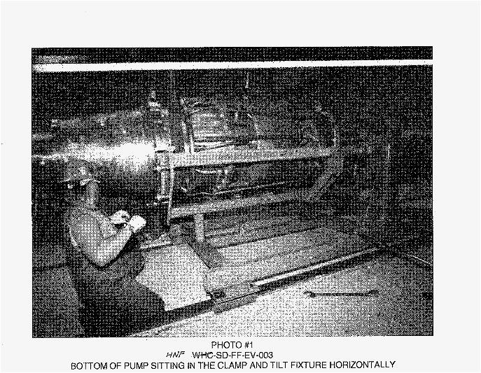
PHOTO #I
BOTTOM OF PUMP SITTING IN THE CLAMP AND TILT FIXTURE HORIZONTALLY H/Vf WkVHC-SD-FF-EV-003


PHOTO #3
VERTICAL PUMP REMOVAL FROM THE CLAMP & TILT FIXTURE M-SD-FF-EV-003
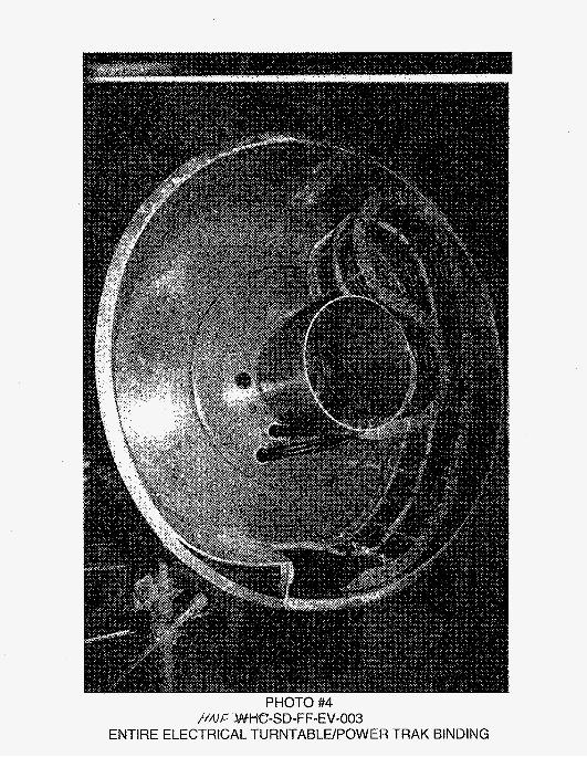
PHOTO #4
ENTIRE ELECTRICAL TURNTABLE/POWER TRAK BINDING h’&F &WHC-SD-FF-EV-O03

PHOTO #5
CLOSEUP OF ELECTRICAL TRUNTABLE/POWER TRAK BINDING HrJ.C-WHC-SD-FF-EV-003

PHOTO #6
20 PSlG NITROGEN LEAK TEST ON THE OIL SYSTEM HUJF AN+tC-SD-FF-EV-003

PHOTO #/
POTTED NEW TERMINAL BOX ASSEMBLY HAJF -W%GSD-FF-EV-O03

PHOTO #8
NEW ELECTRICAL AND INSTRUMENT WIRING TERMINAL BOX ASSEMBLY flflf= JAJtC-SD-FF-EV-003

To From
Distribution Equi pment Engineering Project TitlelWork Order
Test Report f o r Run-In Acceptance Testing o f HMR Pump-3
Babcock & Wilcox B. G. Berglin J . R. Vincent
Page 1 of 1 Date 8/5/97 EDT NO. 617895 ECN No. N/A
N2-01 X N2-02 X
Text Text Only Name MSlN With All
Attach.
Lockheed Martin Hanford Corporation W. G. Brown T4-07 X G. J . Gauck T4-07 X R. R. True T4-07 X
Attach./ EDT/ECN Appendix Only
Only
Lockheed Martin Services Document Control t3-H X
SGN Eurvsis Services CorD. T. R . Benegas C. P. Shaw Project F i 1 es
S7-12 X S7-12 X S7-12 X
A-6000-135 (01/93) WEF067