1 group 11- asme design competition alicia christie desmond bourgeois toddrick ruff
TRANSCRIPT

1
Group 11- ASME Design Competition
• Alicia Christie
• Desmond Bourgeois
• Toddrick Ruff
2
Over View
• Introduction • Needs Assessment and Product Specification • Concept Generation• Prototyping• Final Design• Manufacturing and Assembly• Testing • Cost Analysis• Conclusion• Recommendations / Improvements • Acknowledgement
3
Introduction
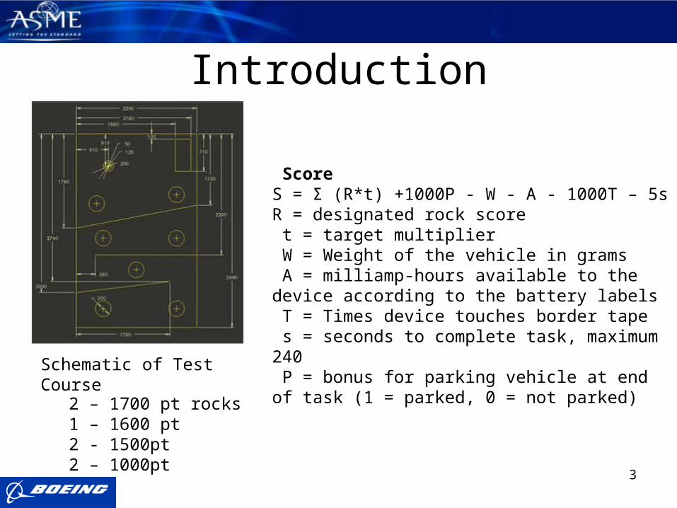
ScoreS = Σ (R*t) +1000P - W - A - 1000T – 5sR = designated rock score t = target multiplier W = Weight of the vehicle in grams A = milliamp-hours available to the device according to the battery labels T = Times device touches border tape s = seconds to complete task, maximum 240 P = bonus for parking vehicle at end of task (1 = parked, 0 = not parked)
2 – 1700 pt rocks1 – 1600 pt 2 - 1500pt2 – 1000pt
Schematic of Test Course

4
Needs Assessment / Product Specification•Must fit into a box 6.5 x 6.5 x 14.5 in
•Needs to have the ability of picking up rocks ranging from 2 to 4 cm
•Deliver rocks to receiving area with accuracy
•Climb over 3.5 in high barriers
•Stay in bounds and maneuver around obstacles
ROBOT
Collection and Transportation
Maneuver over obstacles swiftly
Ejection of rocks

5
Stair Climbing Robot - Mechatronics, Ariel University Center
Zaurus Spiral Stair Climber
Packbot Front-end LoaderPhoenix Mars Lander Robotic Arm
Concept Generation – External Sources

6
Maneuver over obstacles swiftly
Ramp Carrying Robot Tank Drive Individual Tank Treads
Expandable legs Front Spiral
Concept Generation – Internal Sources

7
Collection and Transportation of rocks
Chassis Drop Robotic Arm Street Sweeper Air Jets
Dropping off rocks in receiving area
Dump Truck Style Trap Doors Single Door
Concept Generation – Internal Sources
8
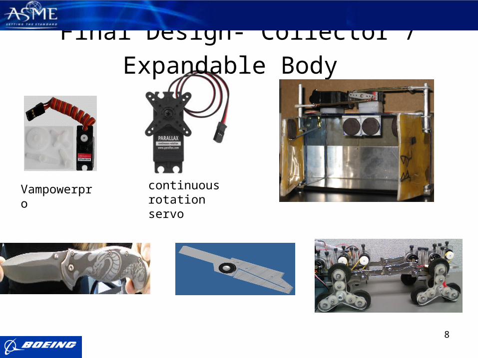
Final Design- Collector / Expandable Body
Vampowerpro continuous rotation servo
9
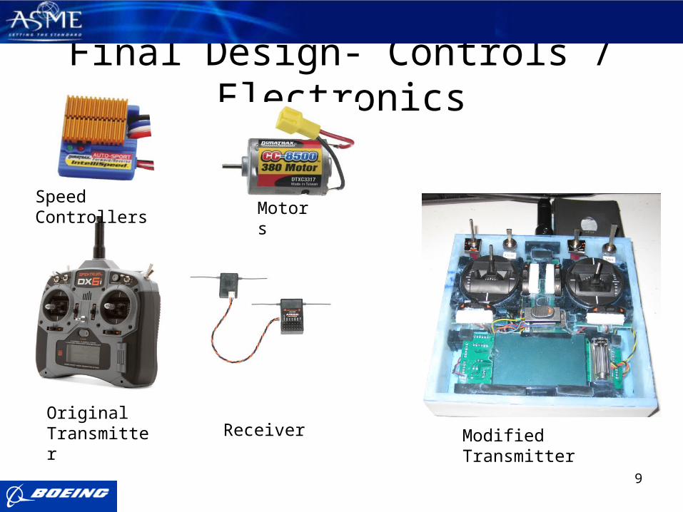
Final Design- Controls / Electronics
Original Transmitter Receiver Modified Transmitter
Speed ControllersMotors
10
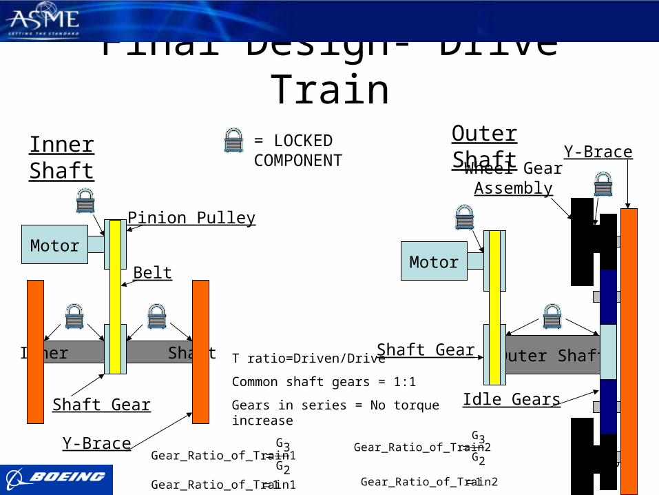
Final Design- Drive Train
Inner Shaft Outer Shaft
Idle Gears
Belt
Y-Brace
Pinion Pulley
Wheel GearAssembly
MotorMotor
Shaft Gear
Y-Brace
Shaft Gear
= LOCKED COMPONENT
Inner Shaft Outer Shaft
Gear_Ratio_of_Train2G3
G2
Gear_Ratio_of_Train2 1
Gear_Ratio_of_Train1G3
G2
Gear_Ratio_of_Train1 1
T ratio=Driven/Drive
Common shaft gears = 1:1
Gears in series = No torque increase
11
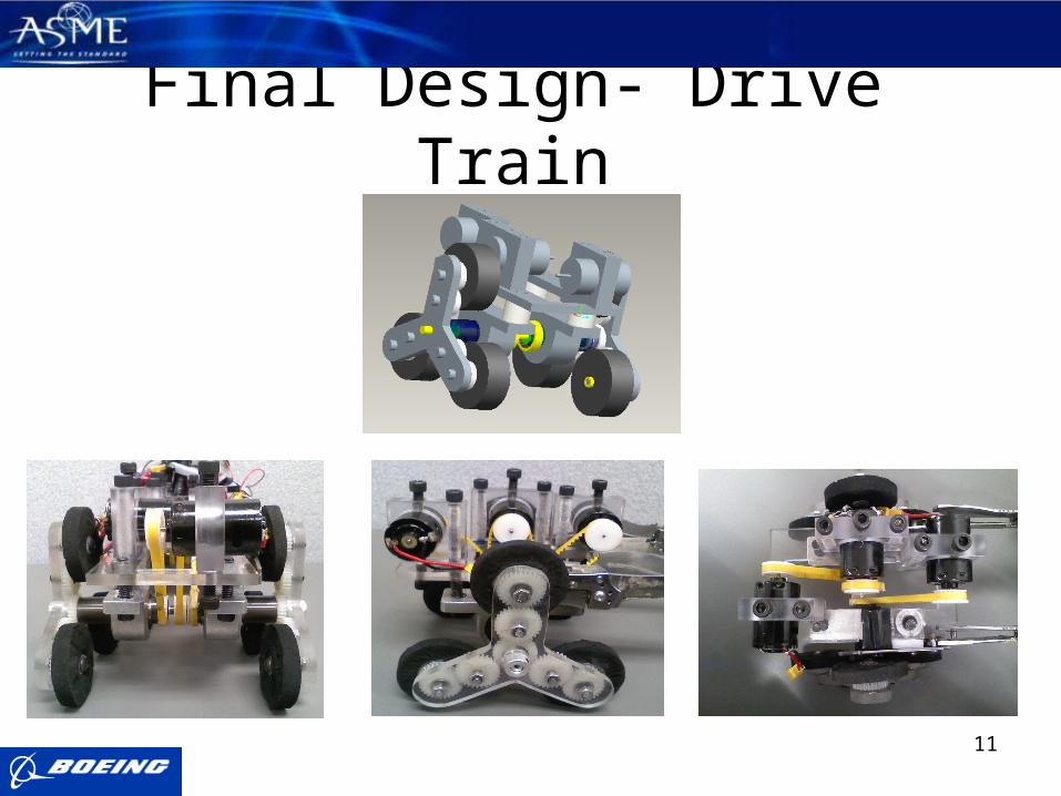
Final Design- Drive Train

12
Manufacturing and Assembly•Used a Dremel Tool for rock collector, knife modifications, and for modifications to the platform to attach the expandable body
•Motor mounts, platform, rear and front drive axel, Y-brackets, and false floor made or modified in machine shop
•Utility knife for removing material from wheels and wires
•Screw drivers
•Allen Wrenches
•Super Glue
•Mighty Putty
•3-56 screws
•Needle Nose Pliers
13
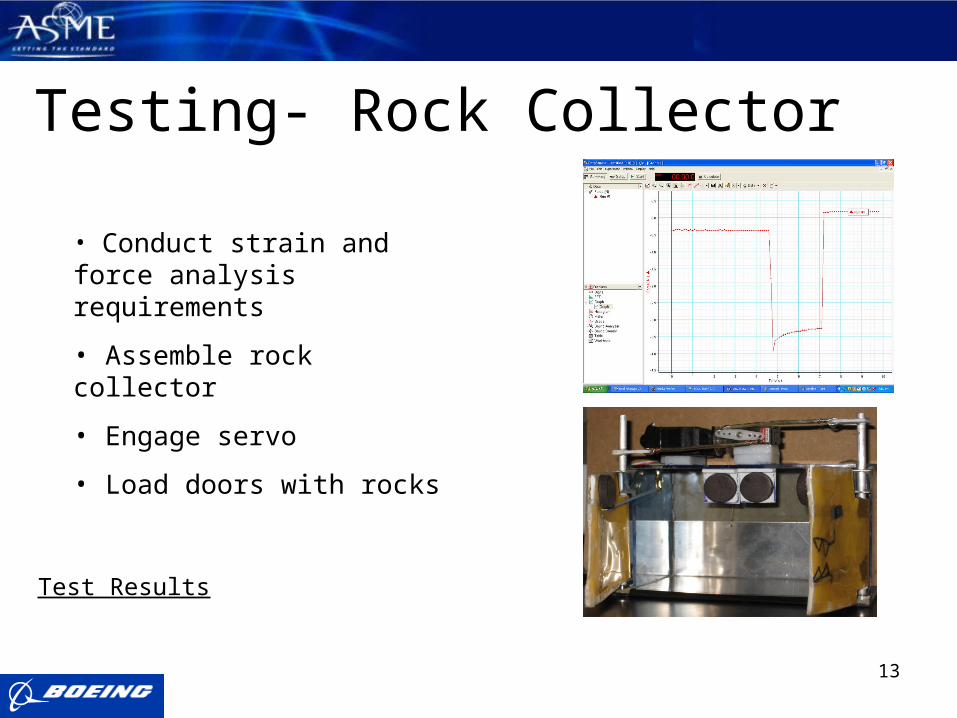
Testing- Rock Collector
• Conduct strain and force analysis requirements
• Assemble rock collector
• Engage servo
• Load doors with rocks
Test Results

14
Testing: Electrical Components• Sizing Batteries
– Motor Test• Simulated Load Test• Strobe Light RPM rating
– Milliamp hour calculation• Total: 1500 mAh
• Wiring Test– Peg board setup
• Component Synchronization• Radio Transmitter/Receiver

15
Testing- Drive Train Trial1
• Fully assemble robot (motors, mounts, belts, etc.)
• Check belt and pulley alignment
• Check belt tension
• Check for collisions of parts
• Engage drive motors
Trial 2 Reiteration of Trial1
Trial 3• Reiteration of Trial1
Test Results
Trial1 = Binding of shafts
Trial 2 = Binding of shafts
Trial 3= Binding of shafts

16

17
Conclusion Ideal Alignment Actual Alignment
Belt Tension
Clearance
Concentration of Belt Force and Friction
Front View Front View
Side View Side View
= LOCKED COMPONENT
Belt Tension
18
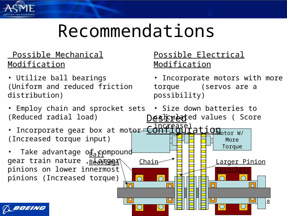
Motor W/ More Torque
Recommendations Possible Mechanical Modification
• Utilize ball bearings (Uniform and reduced friction distribution)
• Employ chain and sprocket sets (Reduced radial load)
• Incorporate gear box at motor (Increased torque input)
• Take advantage of compound gear train nature , Larger pinions on lower innermost pinions (Increased torque)
Possible Electrical Modification
• Incorporate motors with more torque (servos are a possibility)
• Size down batteries to calculated values ( Score increase)
Larger Pinion SprocketsChainBall Bearings
Desired Configuration
19
AcknowledgementsSponsors
American Society of Mechanical Engineers
Boeing
Individuals
Dr. Carl Moore
Dr. Dave Cartes
Dr. Chiang Shih
Dr. Daudi Waryoba