1 glng incidents / lessons learnt csg safety forum john sargaison 14 august 2009
TRANSCRIPT

1
GLNG Incidents / Lessons Learnt
CSG Safety ForumJohn Sargaison14 August 2009

2
Recordable Injuries - YTD
*
Date Severity Rating
Nature of InjuryName of Company
Location Type
06-Jan-09 1Fracture to finger pinched between drilling tongs
Atlas Drilling Atlas Rig #1 Indirect
27-Jan-09 10*Spinal Trauma caused by neck whiplash in truck due to potholes in the road
FKG Springwater Direct
11-Feb-09 10* Struck by falling drill pipe EWG Coxon Creek #8 Indirect
18-Feb-09 1Laceration to hand struck by sledge hammer
Diversified Fairview Field Direct
05-Mar-09 1Sprain to ankle, rolled ankle on edge of path
Valve Tech Fairview Plant Indirect
16-Mar-09 1Fracture to finger pinched between hole cover and equipment
Mitchell Drilling Fairview #408 Indirect
25-Mar-09 10Amputation of L index finger tip
Atlas Drilling Fairview 83 Indirect
31-Mar-09 1 Laceration to finger Select ContractorsKimber Lane Yard
RomaIndirect
11-Apr-09 1 Laceration to finger EWG Fairview #71 Indirect
15-Apr-09 1 Laceration to finger Atlas Drilling Fairview #413 Indirect
22-Apr-09 1Laceration to hand while installing hose
EWG EWG Rig 101 Indirect
09-May-09 1 Crush injury to finger EWG EWG Rig 102 Indirect
13-May-09 1 Back strain handling pipe Bresall Drilling Curtis Is Direct
15-May-09 1 Fracture to finger EWG EWG Rig16 Indirect
16-May-09 10 Fractured vertebrae Atlas Drilling Atlas Rig #1 Indirect

3
Recordable Injuries - TRCFR
*
A direct recordable injury is where GLNG has accountability for the safety of the activity being conducted when the injury occurred.
GLNG Project recordable injury includes injuries where either GLNG or another Business Unit/Department has accountability for the safety of that activity (ie indirect plus direct recordable injuries).
GLNG Total Recordable Case Frequency Rate (TRCFR)
13.011.3 0.00.0 0.0 0.014.521.99.9 18.8
12.3
8.96.7
8.0
10.4
14.115.2
13
6.0
14.2
0
5
10
15
20
25
Feb-09 Mar-09 Apr-09 May-09 Jun-09
TR
CF
R
Monthly Direct TRCFR Monthly Project TRCFRYTD Direct TRCFR YTD Project TRCFR2009 GLNG Direct TRCFR Target

4
LTI – Dropped Drill Collar
IMS #38751
EWG Rig 102 – Coxon Creek 811 February 2009
5
Overview
In preparation for spud, a 5-1/2” drill collar was picked up using the rig’s pipe handling system. The drill collar was latched in the elevators and raised to a near vertical position. When the drill collar was at the near vertical position, the collar slipped through the elevators. The drill collar subsequently landed on the rig’s pipe handling system before bouncing off and landing on the ground/rig floor. A Floorhand received a glancing blow to the lower back while exiting the rig floor by the drill collar as it landed on the rig floor.
6
Summary of Events
At 08:00 on 11 February 2009 the Assistant Driller asked the Mud Tester to gather all of the required equipment for spud. This included the manual 5-1/2” Drill Collar Elevators.- Manual Elevators were to be used due to a broken valve on the hydraulic elevators;
The Rig Manager was waiting on confirmation that the hydraulic elevators could be used with the broken valve
The Mud Tester attached a sling to the 5-1/2” casing elevators and placed them at the front of the parts container. The Forklift Operator transferred the elevators to the V-Door.
At 10:00 the drill bit and bit sub were raised to the floor, along with the casing elevators.
The elevators were fitted to the bails by the Driller, Leasehand and Assistant Driller.
The drill bit and bit sub were made up. The drill collar was then raised to the floor by the pipe handler. The IP latched the casing elevators to the drill collar.
The drill collar was picked up in the elevators. As the drill collar neared the vertical position, the Driller noticed the collar slipping out of the elevators and raised the alarm.
The drill collar fell back to the pipe handler, bounced and fell to the ground and rig floor.
The IP received a glancing blow to the lower back while exiting the rig floor by the drill collar as it landed on the rig floor.
The incorrect elevators were selected for the operation.

7
Overview
5-1/2” Casing Elevators Markings
5-1/2” DC Elevators Markings

8
Overview
Final Position of 5-1/2” Drill Collar
9
Incident Root Causes
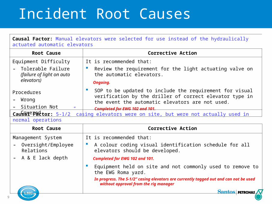
Causal Factor: Manual elevators were selected for use instead of the hydraulically actuated automatic elevators
Root Cause Corrective Action
Equipment Difficulty
- Tolerable Failure(failure of light on auto elevators)
Procedures
- Wrong
- Situation Not Covered
It is recommended that: Review the requirement for the light actuating valve on the automatic
elevators.
Ongoing.
SOP to be updated to include the requirement for visual verification by the driller of correct elevator type in the event the automatic elevators are not used.Completed for EWG 102 and 101.
Causal Factor: 5-1/2” casing elevators were on site, but were not actually used in normal operations
Root Cause Corrective Action
Management System
- Oversight/Employee Relations
- A & E lack depth
It is recommended that: A colour coding visual identification schedule for all elevators should be
developed.
Completed for EWG 102 and 101.
Equipment held on site and not commonly used to remove to the EWG Roma yard.In progress. The 5-1/2” casing elevators are currently tagged out and can not be used
without approval from the rig manager
10
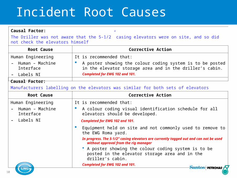
Incident Root CausesCausal Factor:
The Driller was not aware that the 5-1/2” casing elevators were on site, and so did not check the elevators himself
Root Cause Corrective Action
Human Engineering
- Human – Machine Interface
- Labels NI
It is recommended that: A poster showing the colour coding system is to be posted in the elevator
storage area and in the driller’s cabin.Completed for EWG 102 and 101.
Causal Factor:
Manufacturers labelling on the elevators was similar for both sets of elevators
Root Cause Corrective Action
Human Engineering
- Human – Machine Interface
- Labels NI
It is recommended that: A colour coding visual identification schedule for all elevators should be
developed.
Completed for EWG 102 and 101.
Equipment held on site and not commonly used to remove to the EWG Roma yard.In progress. The 5-1/2” casing elevators are currently tagged out and can not be used
without approval from the rig manager
A poster showing the colour coding system is to be posted in the elevator storage area and in the driller’s cabin.
Completed for EWG 102 and 101.
11
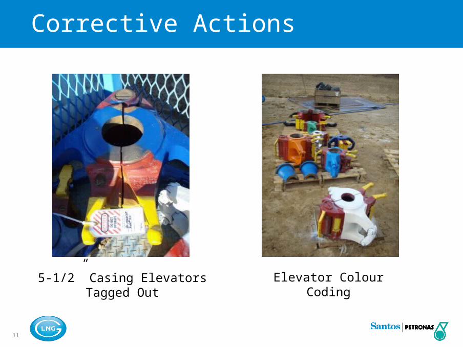
Corrective Actions
5-1/2” Casing Elevators Tagged Out
Elevator Colour Coding
12
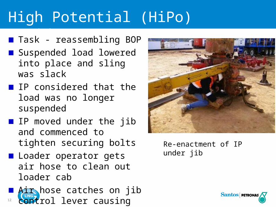
High Potential (HiPo) Incident SummaryTask - reassembling BOP
Suspended load lowered into place and sling was slackIP considered that the load was no longer suspended IP moved under the jib and commenced to tighten securing boltsLoader operator gets air hose to clean out loader cabAir hose catches on jib control lever causing it to lower
Re-enactment of IP under jib

13
LTI – Back Injury
IMS #42241
Atlas Rig 1 – Fv122_OB1
13:25 16 May 2009

14
Overview
Maintenance was being carried out on the BOP during rig move.
While replacing the kill line valve, the IP positioned himself under the loader jib. Coincidental with this, the loader operator pulled a compressed air line through the window of the loader to clean the cab. The air line made contact with the loader controls causing the loader jib to descend. The loader jib stopped when it made contact with the valve it was previously suspending. The loader jib pinned the IP in the crouched position causing two fractured vertebrae. The IP was evacuated to Injune hospital for medical treatment and later to Toowoomba for precautionary MRI scan.

15
Summary of Events
At 13:00hrs the work party commenced re-assembly of the kill line valve block back onto the BOP. The kill line valve block was manoeuvred into position a using loader stinger jib and soft sling.
With correct alignment achieved, the flange was fitted onto the studs. Under direction, the loader jib was lowered slightly causing the sling to slacken, indicating weight of the valve block was now being fully taken by BOP studs. Derrickman and Floorman commenced tightening nuts onto flange.
Loader Operator steped out of loader to grab compressed air line to “blow” clean loader cab. Operator routed hose through cab window with hose passing close to jib control levers.
Loader Operator climbed back into cab and commenced cleaning the loader cab.
Derrickman positioned himself under the loader jib to tighten nuts onto the valve block flange.
At 13:24hrs, the Floorman noticed the loader jib descending at approximately 150mm/sec. The Floorman attempted to get attention of Loader Operator to alert him.
IP becomes pinned in the crouched position beneath loader jib and BOP stump skid. The end of the jib contacts the valve block flange surface preventing further downwards travel.
IP evacuated from site. IP sustained two fractured vertebrae.

16
Overview
Re-enactment if IP’s position under jib.
Photo showing air hose path through cab RHS window and across control levers

17
Overview
Step-back conducted before operation
Loader Operator (Driller) hadForklift Licence and ~25 yearsloader experience
Crew did not consider loaderjib as a suspended load

18
Incident Root Causes
Causal Factor:
Driller runs air hose through RHS window of loader cab - across control levers
Corrective Action
Loader operator considered his part of the job to be over once the valve was secured.
Loader operator was focused on a a second task (not the position of the jib).
It is recommended that:- Loader Operations Procedures be revised to include warnings regarding operator
attention during use.
- High impact sign in cab warning of hazards of inattention and leaving cab whilst loader running.
- The inclusion of a special section on loader safety as part of Level 3 induction
- Confirmation of safety systems running as part of loader pre-start checks
- A training refresher for all loader drivers in field
- A review of the controls layout for all loaders in field
- Distribution of a Haz Alert followed by a visit to all rig crews by Santos Field Safety Advisor to discuss
19
Incident Root Causes
Causal Factor: IP positioned under loader jib
Corrective Action
IP did not consider loader jib to be a suspended load once valve was removed.
It is recommended that:- A warning be placed on the jib warning of the dangers of working under suspended loads and
unexpected operation of the loader
- The inclusion of a special section on loader safety as part of Santos Level 3 induction
- Distribution of a Haz Alert followed by a visit to all rig crews by Santos Field Safety Advisor to discuss