1 gas-filled capillary discharge waveguides simon hooker, tony gonsalves & tom rowlands-rees...
TRANSCRIPT

1
Gas-Filled Capillary Discharge Waveguides
Simon Hooker, Tony Gonsalves & Tom Rowlands-Rees
Collaborations
Alpha-X Basic Technology programme (Dino Jaroszynski et al)
LBNL (Wim Leemans et al.)
Department of Physics
University of Oxford
2
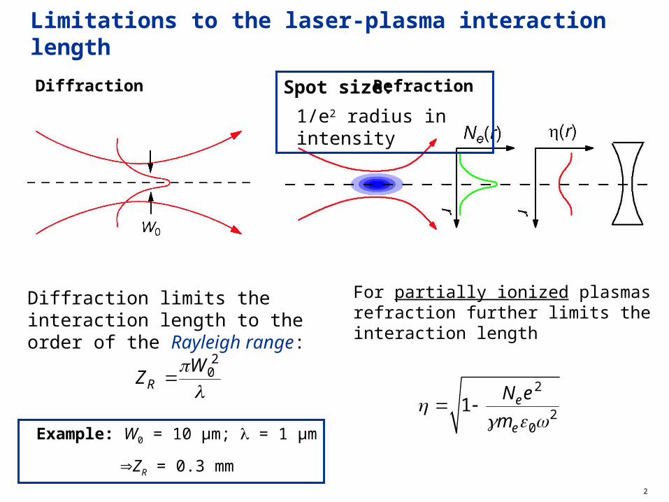
Limitations to the laser-plasma interaction length
Diffraction Refraction
Diffraction limits the interaction length to the order of the Rayleigh range:
2
0R
WZ
Example: W0 = 10 µm; = 1 µm
ZR = 0.3 mm
For partially ionized plasmas refraction further limits the interaction length
2
20
1 e
e
N e
m
Spot size:
1/e2 radius in intensity

3
Gradient refractive index guiding - Plasma waveguides
For non-relativistic intensities the refractive index of a plasma may be written:
2( ) (0) /e e e chN r N N r r
supports matched guiding of Gaussian beams with a constant spot size:
1/ 42ch
Me e
rW
r N
Hence a parabolic electron density profile:
2 2
2 20 0
11 1
2e e
e e
N e N e
m m

4
Gas-filled capillary discharge waveguide: Overview
• Channels laser machined in sapphire blocks
• Channel 200 - 400 μm diameter
• Gas injected near each end of channel
H2 gas
vacuum vacuumbellows
channel
+V 0V
electrode
laser
D. J. Spence et al. Phys. Rev. E 63 015401(R) (2001)
• Gas ionized by pulsed discharge
– Peak current 100 - 500 A
– Rise-time 50 - 100 ns

5
• Channels laser machined in sapphire blocks
• Channel 200 - 400 μm diameter
• Gas injected near each end of channel
H2 gas
vacuum vacuumbellows
channel
+V 0V
electrode
laser
• Gas ionized by pulsed discharge
– Peak current 100 - 500 A
– Rise-time 50 - 100 ns
Gas-filled capillary discharge waveguide: OverviewD. J. Spence et al. Phys. Rev. E 63 015401(R) (2001)

6
Mechanism of Channel Formation – MHD Simulation
• No pinch effect is observed
• Plasma fully ionized for t > 50 ns
• Ablation of capillary wall found to be negligible
Bobrova et al. Phys. Rev. E 65 016407 (2001)

7
Discharge reaches a quasi equilibrium in which Ohmic heating of plasma is balanced by conduction of heat to wall:
210e
d dTr E
r dr dr
Solution of the heat flow equation yields a scaling relation for the matched spot size:
5
1/ 4-3
[μm][μm] 1.5 10
[cm ]M
e
aW
N
Mechanism of Channel Formation – MHD SimulationBobrova et al. Phys. Rev. E 65 016407 (2001)

8
Guiding With Square Capillaries
Transmission = 90%t = 115 nsGuided spot 27 × 32 µm
• 33 mm long, 400 μm square capillary
• 120 mbar H2
• Transmitted spots ~ same size as input spot

9
Guiding With Square Capillaries
(a) Input intensity 5.8 1016 W cm-2; W ~ 28 μm
(b) Exit: Unguided Output Spot t <0ns
(c) Exit t =115ns
10
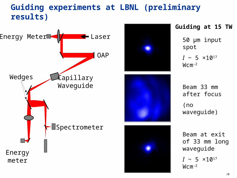
Guiding experiments at LBNL (preliminary results)
Energymeter
Wedges
Spectrometer
OAP
CapillaryWaveguide
Energy Meter Laser
Guiding at 15 TW
50 μm input spot
I ~ 5 ×10¹⁷ Wcm-2
Beam 33 mm after focus
(no waveguide)
Beam at exit of 33 mm long waveguide
I ~ 5 ×10¹⁷ Wcm-2

11
Transverse interferometry
Nd:YAG
camera
1.2
1.1
1.0
0.9
0.8
0.7
Ele
ctro
n D
ensi
ty (
1018
cm
-3)
Position in Capillary0( ) ( )
L
y y dxc
60 mbar140 ns
12
10
100
1000
1.0E+15 1.0E+16 1.0E+17 1.0E+18 1.0E+19
Electron density (cm-3
)
Mat
ched
sp
ot
size
(mm
)
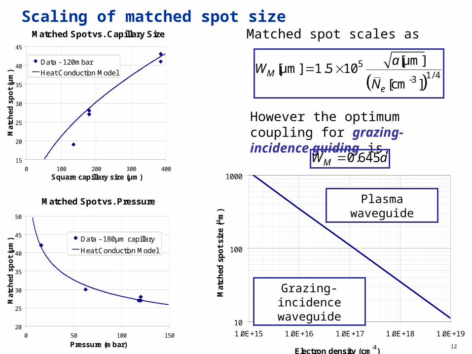
Scaling of matched spot sizeMatched Spot vs. Capillary Size
15
20
25
30
35
40
45
0 100 200 300 400
Square capillary size (μm)
Mat
ched
sp
ot
(μm
)
Data - 120mbar
Heat Conduction Model
Matched Spot vs. Pressure
20
25
30
35
40
45
50
0 50 100 150
Pressure (mbar)
Mat
ched
sp
ot
(μm
) Data - 180μm capillary
Heat Conduction Model
However the optimum coupling for grazing-incidence guiding is,
0.645MW a
Matched spot scales as
5
1/ 4-3
[μm][μm] 1.5 10
[cm ]M
e
aW
N
Plasma waveguide
Grazing-incidence waveguide

13
Summary
Advantages
• Guiding of laser pulses with peak intensities of ~ 5 × 10¹⁷ Wcm-2 over 33 mm demonstrated
• High pulse energy and peak intensity transmission
• Low coupling losses
• Long device lifetime demonstrated
• Should be able to be staged
Disadvantages
• Guided spot size relatively large (> 20 µm)
• Spot size becomes even larger at low plasma densities