1. feature of mh plant controller - primetals. feature of mh plant controller ... image processing...
TRANSCRIPT
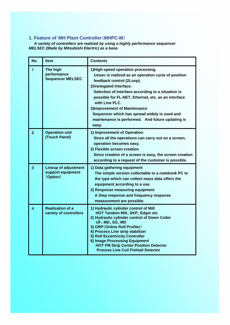
1. Feature of MH Plant Controller(MHPC-M)A variety of controllers are realized by using a highly performance sequencer
MELSEC (Made by Mitsubishi Electric) as a base.
1) Hydraulic cylinder control of MillHOT Tandem Mill、SKP、Edger etc
2) Hydraulic cylinder control of Down CoilerUF、MD、SG、MD
3) ORP(Online Roll Profiler)4) Process Line strip stabilizer5) Roll Eccentricity Controller6) Image Processing Equipment
HOT FM Strip Center Position DetectorProcess Line Coil Fishtail Detector
Realization of a variety of controllers
4
1) Data gathering equipmentThe simple version collectable to a notebook PC to the type which can collect mass data offers the equipment according to a use.
2) Response measuring equipmentA Step response and frequency responsemeasurement are possible.
Lineup of adjustment support equipment(Option)
3
1) Improvement of OperationSince all the operations can carry out on a screen, operation becomes easy.
2) Flexible screen creationSince creation of a screen is easy, the screen creationaccording to a request of the customer is possible.
Operation unit (Touch Panel)
2
1)High-speed operation processing.1msec is realized as an operation cycle of position feedback control (2Loop).
2)Variegated Interface.Selection of Interface according to a situation is possible for FL-NET, Ethernet, etc. as an interface with Line PLC.
3)Improvement of MaintenanceSequencer which has spread widely is used andmaintenance is performed. And future updating is easy.
The high performance Sequencer MELSEC
1
ContentsItemNo
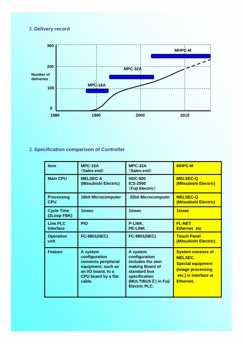
1980 1990 2000 2010
MPC-16A
MPC-32A
MHPC-M
100
300
0
200
Number of deliveries
2. Delivery record
3. Specification comparison of Controller
System consists of MELSEC.Special equipment (image processingetc.) is interface at Ethernet.
A system configuration includes the own making Board of standard bus specification (MULTIBUSⅡ) in Fuji Electric PLC.
A system configuration connects peripheral equipment, such as an I/O board, to a CPU board by a flat cable.
Feature
Touch Panel(Mitsubishi Electric)
FC-9801(NEC)FC-9801(NEC)Operation unit
FL-NETEthernet etc
P-LINK,PE-LINK
PIOLine PLCInterface
1msec1msec1msecCycle Time(2Loop FBK)
MELSEC-Q(Mitsubishi Electric)
32bit Microcomputer16bit MicrocomputerProcessing CPU
MELSEC-Q(Mitsubishi Electric)
HDC-500ICS-2500(Fuji Electric)
MELSEC-A(Mitsubishi Electric)
Main CPU
MHPC-MMPC-32A(Sales end)
MPC-16A(Sales end)
Item
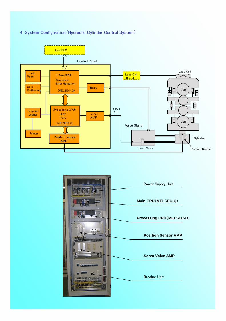
Power Supply Unit
Main CPU(MELSEC-Q)
Processing CPU(MELSEC-Q)
Position Sensor AMP
Servo Valve AMP
Breaker Unit
4. System Configuration(Hydraulic Cylinder Control System)
Load Cell
Valve Stand
Servo Valve
Control Panel
WR
BUR
WR
BUR
Position Sensor
CylinderPosition sensorAMP
TouchPanel
Relay
Servo
AMP
ServoREF
< MainCPU >
・Sequence・Error detection
(MELSEC-Q)
<Processing CPU>
・APC
(MELSEC-Q)
Load Cell
Panel
Line PLC
Printer
ProgramLoader
DataGathering
・AFC

5.Display of Operation unit (Touch Panel)
① Status Display
② Test Mode Display

③Analog Monitor
④ Error History
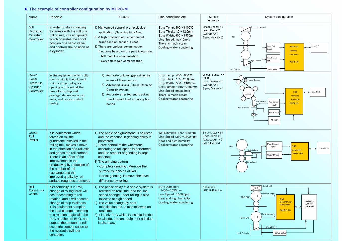
6. The example of controller configuration by MHPC-M
Absocoder(64PLS/Rotation)
BUR Diameter:1450~1655mm
Line Speed :1680mpmHeat and high humidityCooling-water scattering
1) The phase delay of a servo system is rectified on real time, and the line speed change under rolling is also followed at high speed.
2) The value change by heat modification etc. is also followed on real time.
3) It is only PLG which is installed in the local side, and an equipment addition is also easy.
If eccentricity is in Roll, change of rolling force will occur according to roll rotation, and it will become change of strip thickness. This equipment samples the load change according to a rotation angle with the PLG attached to BUR, and outputs the amount of roll eccentric compensation to the hydraulic cylinder controller.
RollEccentricityControl
Servo Motor×14Encorder×12Absocoder ×2Load Cell×4
WR Diameter:575~680mmLine Speed :350~1600mpmHeat and high humidityCooling-water scattering
1) The angle of a grindstone is adjustedand the variation in grinding ability is prevented.
2) Force control of the whetstone according to roll speed is performed, and the amount of grinding is kept constant.
3) The grinding pattern - Complete grinding : Remove the surface roughness of Roll.
- Partial grinding: Remove the level difference by rolling.
It is equipment which forces on roll the grindstone installed in the rolling mill, makes it move in the direction of a roll axis, and grinds the roll surface. There is an effect of the improvement in the productivity by reduction of the number of roll exchange and the improved quality by roll surface roughness removal.
OnlineRollProfiler
Linear Sensor×4PT×8Laser Sensor×2Cylinder×4Servo Valve×4
Strip Temp :400~600℃Strip Thick :1.2~20.0mmStrip Width :500~2180mmCoil Diameter:915~2600mmLine Speed :max15m/sThere is mach steamCooling-water scattering
1) Accurate unit roll gap setting by
means of linear sensor
2) Advanced Q.O.C. (Quick Opening
Control) system
3) Accurate strip top end tracking
Small impact load at coiling first
period
In the equipment which rolls round strip, it is equipment which carries out quick opening of the roll at the time of strip top end passage, decreases a top mark, and raises product quality.
Down CoilerHydraulicCylinderController
Linear Sensor×2Load Cell×2Cylinder×2Servo valve×2
Strip Temp:400~1100℃Strip Thick:1.0~12.0mmStrip Width:900~1550mmLine Speed:max15m/sThere is mach steamCooling-water scattering
1) High-speed control with exclusive
application. (Sampling time:1ms)
2) A high precision and environment
proof position sensor is used.
3) There are various compensation
functions based on the past know-how.
- Mill modulus compensation
- Servo flow gain compensation
In order to strip to setting thickness with the roll of a rolling mill, it is equipment which operates the spool position of a servo valve and controls the position of a cylinder.
MillHydraulicCylinderController
System configurationSensorActuator
Line conditions etcFeaturePrincipleName
Load Cell
Panel
Pos. Sensor
AMP
Hyd. Cylinder
Pos. Sensor
Servo Valve
Load Cell
Line PLC
Mill
Hydraulic
Cylinder
Controller
(MHPC-M)
PT AMP
Pos. Sensor
AMP
Mandrel
Pos. Sensor
Servo ValvePT
QOC
Hydraulic
Controller
(MHPC-M)
Line PLC
Hyd. Cylinder
Laser Sensor
Grindstone
Motor Driver
Pos. SensorAMP
Grindstone
ORP
Controller
(MHPC-M)
Line PLCMill
Rotation angle
(MHPC-M)
Hyd. Cylinder
Pos. Sensor
Servo Valve
Load Cell
Hydraulic Cylinder Controller
TOP BUR
rotation angle
BTM BUR
Roll EccentricityController

CCD Camera×1Halogen Light×1PLG×1Laser Sensor ×3
Coil Dia:1200~2100mm
Coil Width:600~1350mm
Coil Rotation Speed:330mm/sec
1)Accuracy (Fish tail position accuracy: ±50mm)
Exclusive H/W and Algorithm have realized.
2) It is non-contact type equipment using CCD camera,
and stable detection can be performed.
3) With various image-processing technology, the
character on Coil, rust, Oil, etc. carry out disturbance
removal.
It is equipment which glares lighting from the lower part of Coil which rotates on Cradle, catches the shadow generated in a part for a tail end in CCD Camera, and detects a Coil fish tailposition. It aims at automation of entryside of process line.
CoilFish TailDetector
CCD Camera×4Purge Air:
2Nm3/minCooling water:40l/min
Strip Temp:400~1100℃Strip Thick:1.0~12.0mmStrip Width:900~1550mmLine Speed:max1680mpmThere is mach steamCooling-water scattering
Camera Position:Path Line+700~800mm
1) Accuracy : Within±1.0mm
Accuracy is improved by triangulation, automatic
correction of camera position etc.
2) Cycle time:Less than 5.0ms
High speed operation processing using CPU
(Peintium M).
3) Environment-proof:
Eliminating influence of steam, water drops, etc. using
high performance purge device. Easy maintenance
because of no back light.
It is equipment which installs a CCD camera on the side guide between stands, detects the edge of strip, and calculates the strip center position and width.A signal is used for strip threading stability and strip tail pinching prevention and strip width control.
StripCenterPositionDetector
Eddy Current×8Electromagnet ×28
Strip Thick:0.3~3.2mmStrip Width:610~1610mmLine Speed:150mpmAL Coating Temp:660℃
1) Force of magnet : 10.5kgf/p’ce2) Amplitude of vibration: < 30% (Freq 0-10Hz)3) Correction of strip shape:
10mm p-p -> 2mm p-p (0.8mm t)4)Adjustment of pass line: 5-10mm
Strip Stabilizer system using electromagnet can correct a strip wrap, adjust a pass line position and reduce a strip vibrationFlat strip shape at air knife leads to:-Uniform coating-Less consumption of molten zinc
StripStabilizer
System configurationSensorActuator
Line conditions etcFeaturePrincipleName
Electromagnet
Pos. SensorAMP
Servo Driver
Pos Sensor
Coating Pot
StripStabilizerController(MHPC-M)
Line
PLCElectromagnet
Camera AMP
BOXCCD Camera
Strip
StripCenter Pos.
Detector(MHPC-M)
上位 PLC
Side Guide
Coil
CCD Camera
Cradle Roll
CoilFish TailDetector
(MHPC-M)
Line
PLC
Light
PLG Pulse

<Sample of data gathering display>
7. Adjustment support equipment (OPTION)As peripheral equipment of controller, we offer following equipment as option.(1) Data gathering equipment
This system consists of the notebook PC for the data gathering and indication, HDD for storing data and printers for printing a graph.This system receives data a constant cycle from a controller.Moreover, there are functions, such as a graph display and an output to CSV file.
Data Gathering PCHDD Printer
USB USB
For storing data For printing dataEthernet
Controller Controller

(2) Response measuring equipment
Freq. Response
This system has two types of analysis functions (step response test & frequency response test) to analyze the response of hydraulic cylinders.Especially automatic analyze function will save your labor. Measuring result of this function can be revised by the mouse-driven interface.Besides, 2 cylinders are analyzable at the same time. It increases your operating efficiency.
Isolation Module
Printer
Control System
Note PC
I/O Card
Analog OutputAnalog Input Step Response
Reference Signal×1,Cylinder Position Feed Back (or Force Feed Back)×2,Valve Travel×2
sampling period: 10kHz (0.1ms)Step Response Test
Reference Signal×1,Cylinder Position Feed Back×2 (2 axis simultaneous measuring executable)
measuring range: 0.1~50.0Hz (40Step / Decade)
Frequency Response Test
Measuring Signals Spec Function Name
Specifications
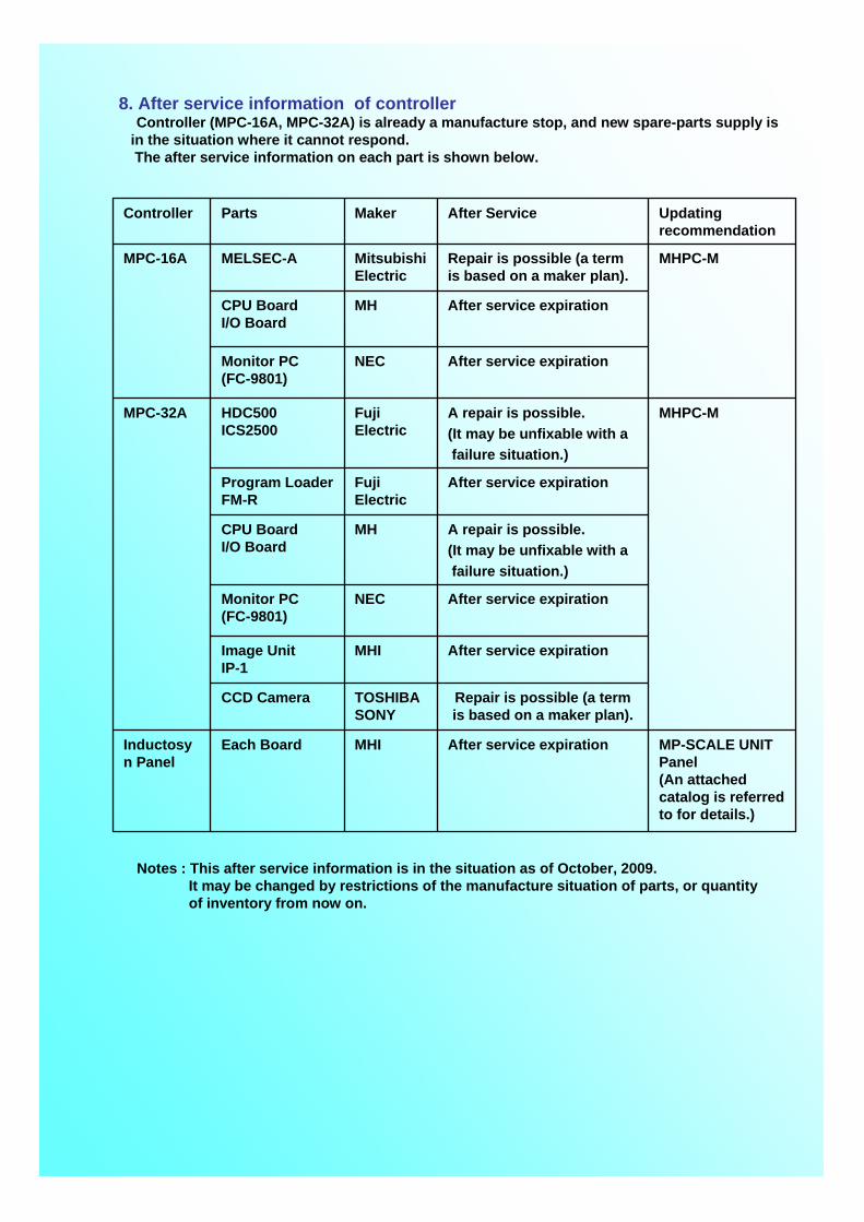
8. After service information of controllerController (MPC-16A, MPC-32A) is already a manufacture stop, and new spare-parts supply is
in the situation where it cannot respond.The after service information on each part is shown below.
MP-SCALE UNIT Panel(An attached catalog is referred to for details.)
After service expirationMHIEach BoardInductosyn Panel
Repair is possible (a term is based on a maker plan).
TOSHIBASONY
CCD Camera
After service expirationMHIImage UnitIP-1
After service expirationNECMonitor PC(FC-9801)
A repair is possible.(It may be unfixable with afailure situation.)
MHCPU BoardI/O Board
After service expirationFuji Electric
Program LoaderFM-R
MHPC-MA repair is possible.(It may be unfixable with afailure situation.)
Fuji Electric
HDC500ICS2500
MPC-32A
After service expirationNECMonitor PC(FC-9801)
After service expirationMHCPU BoardI/O Board
MHPC-MRepair is possible (a term is based on a maker plan).
Mitsubishi Electric
MELSEC-AMPC-16A
Updating recommendation
After Service MakerPartsController
Notes : This after service information is in the situation as of October, 2009.It may be changed by restrictions of the manufacture situation of parts, or quantity of inventory from now on.
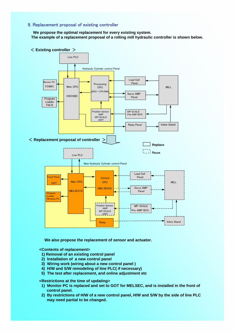
Replace
Reuse
9. Replacement proposal of existing controller
We propose the optimal replacement for every existing system.The example of a replacement proposal of a rolling mill hydraulic controller is shown below.
< Existing controller >
< Replacement proposal of controller >
We also propose the replacement of sensor and actuator.
<Contents of replacement>1) Removal of an existing control panel2) Installation of a new control panel3) Wiring work (wiring about a new control panel )4) H/W and S/W remodeling of line PLC( if necessary)5) The test after replacement, and online adjustment etc
<Restrictions at the time of updating>1) Monitor PC is replaced and set to GOT for MELSEC, and is installed in the front of
control panel.2) By restrictions of H/W of a new control panel, H/W and S/W by the side of line PLC
may need partial to be changed.
Hydraulic Cylinder control Panel
Monitor PC
FC9801
Load Cell PanelProcessing
CPU
(M32-CPU386)
Main CPU
(HDC500)
Position Sensor AMP
MP-SCALEUNIT
Servo AMP Panel
MP-SCALEPre-AMP BOX
Relay Panel Valve Stand
Line PLC
MILL
ProgramLoaderFM-R
New Hydraulic Cylinder control Panel
Touch Panel
GOT
Load Cell PanelControl
CPU
(MELSEC-Q)
Main CPU
(MELSEC-Q)Servo AMP
Panel
MP-SCALE
Pre-AMP BOX
Valve Stand
Line PLC
MILL
Program LoaderWindows PC
Relay
Position Sensor AMP
MP-SCALEUNIT