1, f. tarlochan2, a.m.s. hamouda2 and k. al khalifa3
TRANSCRIPT

Journal of Mechanical Engineering and Sciences (JMES)
ISSN (Print): 2289-4659; e-ISSN: 2231-8380; Volume 9, pp. 1734-1743, December 2015
© Universiti Malaysia Pahang, Malaysia
DOI: http://dx.doi.org/10.15282/jmes.9.2015.19.0167
1734
Energy absorption capability of thin-walled aluminium tubes under crash loading
P. Khalili1, F. Tarlochan2, A.M.S. Hamouda2 and K. Al – Khalifa3
1Center for Innovation and Design, Universiti Tenaga Nasional, Malaysia
2Department of Mechanical and Industrial Engineering,
Qatar University, Doha, Qatar 3Qatar Road Safety Studies Center, Qatar University, Doha, Qatar
Email: [email protected]
Phone: +974 44034367 and +974 4403 4301
ABSTRACT
This paper investigates the interaction of design factors such as tube thickness, tube
length, and tube cross-sectional aspect ratio, along with friction and impacting mass on
crashworthiness parameters such as specific energy absorption contact time, peak force
and crush distance. The impact velocity is assumed to be constant at 15 m/s. The focus is
on rectangular aluminium tubes and the analysis was carried out by using a validated
finite element model. The analysis shows that the factors are not independent of each
other and there is some degree of interaction between them. It was found that the trigger
mechanism is a very important design factor to be included in the design of thin-walled
tubes for energy absorption applications. The effect of the friction coefficient was found
to be insignificant and finally, based on the interactions, it can be concluded that the most
effective design would be a larger tube with small wall thickness, and a larger aspect ratio
to avoid buckling.
Keywords: Impact load; thin-walled tubes; energy absorption; trigger mechanism.
INTRODUCTION
In any collision between vehicles, kinetic energy has to dissipate in a controlled manner
that will protect the occupants in the vehicle from bodily injuries or fatalities. Thin-walled
tubular metallic structures are very efficient as energy absorbers and can be easily
designed into a vehicle’s frontal protection system [1]. These metallic thin-walled
structures have the capability to convert the kinetic energy to strain energy by irreversible
plastic deformation. Most of the reported works in the literature on such tubes have used
mild steel as the base material for understanding the energy absorption efficiency.
However, in the light of efficient fuel economics, aluminium as a lightweight material is
gaining popularity [2]. In terms of the works reported on aluminium as an efficient energy
absorber, most of them can be categorized as the following investigations; (a) effect of
cross-sectional geometry [3-7], (b) effect of trigger mechanisms [8-12], (c) effect of
boundary conditions [13-16], (d) effects due to innovative designs [6, 16-23] , (e) effect
of failure mechanism and (f) effect of fillers such as foams [24-27]. For the cross-
sectional geometries, a buckling initiator using inertia force for a hat-shaped cross-section
improved the energy absorption for aluminium tubes [3]. For square tubes, the response
is very dependent on impact velocity, and the deformation at transition from progressive
collapse to buckling increases with increasing impact velocity due to inertia forces [4]. It
has been proven that deviating from standard square or rectangular cross-sectional tubular

Energy absorption capability of thin-walled aluminium tubes under crash loading
1735
designs to a polygonal section in the form of a hexagon or octagon can further enhance
the energy absorption capabilities of such aluminium tubular structures [5]. In a separate
study [6], thin-walled structures consisting of spherical shells merging into conical frusta
of various geometries showed collapse mechanisms that proved them to have potential as
energy absorbing devices.
Trigger mechanisms are used to initiate progressive folding on thin tubular
structures and at the same time to lower the maximum peak force. A trigger mechanism
can be explained as a “defect” in the structure which causes the structure to fail first at
the location of the trigger. In a study by Lee et al.[8], it was found that trigger mechanisms
that are located at the pitch length of the folding wave enhance the energy absorption
capability of the tube. In a study investigating grooves on tubes [9], it was found that the
folding process of the tubes could be controlled by the introduction of grooves with
different distances and hence achieved the desired load uniformity. Similar findings were
obtained in a separate study [10] investigating longitudinally grooved square tubes. Zhang
et al.[11] have designed a new trigger mechanism attached to the structure and the novel
design has proven to improve the energy absorption and lower the initial peak force.
Trigger mechanisms in the form of circumferential strain concentration on corrugated
tube surfaces have shown good design initiatives towards enhancing energy absorption
[12]. In most of the reported works pertaining to the energy absorption of aluminium
tubes, there are no discussions or findings relating to the interaction between design
factors on the desired responses. The objective of this study is to investigate the effect of
the interaction of design factors on the energy absorption capabilities of aluminium tubes.
FINITE ELEMENT ANALYSIS
The finite element model of the tube consists of shell elements with an element size of 5
mm (after sensitivity analysis of mesh size). The tube was constrained at the base
(boundary condition). The impactor was designed as a rigid element and was only allowed
to move along the longitudinal axis of the tube. The impactor has an initial velocity of 15
m/s. This is to simulate the axial loading condition. The material used is aluminium 6063
T5, where the strain rate has no significant influence on the hardening behaviour up to
103 s-1 [28-30] . The mechanical properties are the Young’s modulus E = 71000 MPa,
yield stress = 200 MPa and the density = 2700 kg/m3. The nominal strain-stress curve
is obtained from the following reference. The hardening modulus is defined for the
nominal strain-stress curve, 500 and 209 MPa for the true strains p < 0.04 and p > 0.04,
respectively. Besides, imperfections are considered to trigger the asymmetric buckling
mode of the structure [29]. In this step, the experiment set-up in the literature [2] of the
square tube subjected to axial loading was modelled and the results were compared. The
square tube had the width 23.7 mm, length 146 mm and wall thickness 1.14 mm.
Comparison of the contact time, crush distance, initial peak force and energy absorption
between the FE model and the experimental tests [29] was carried out. Table 1 displays
the loading condition of the structures and it can be seen that there is a satisfactory
agreement between the FE model and experiment for impact energy, and the deflections
of all structures had a good correlation with the experimental test. Comparison of the
contact time between the experiment and FE model is depicted in Table 2, proving the
close correlation of crush time. Figure 1 also demonstrates a reasonable trend of contact
time versus dynamic force for the N-1-B between the FE model of this study and the
experiment. Figure 2 represents the deformed profile of the experimental and numerical
tests by and the FE model of this study, which illustrates the number and location of the

Khalili et al. / Journal of Mechanical Engineering and Sciences 9(2015) 1734-1743
1736
folds. For N-1-B, N-2-C and N-3-D, lobes were placed in the lower part of the crushed
tubes. For N-4-E, the wrinkles matched well with the experiment, in which two big
wrinkles formed, one in the upper and another in the lower part of the structure. The upper
lobe crushed more than the lower one.
Table 1. Comparison between experimental and finite element analysis.
Specimen V (m/s) M (kg) Energy absorption (J) Deflection
(mm)
Ref. [2] FE model
(current study)
Ref. [2] FE model
(current study)
N-1-B 15.91 0.95 120 120 6.2 6
N-2-C 35.35 0.44 275 275 20.9 21.7
N-3-D 64.62 0.103 215 212 9.2 11.1
N-4-E 91.35 0.103 431 428 25.7 25.1
Table 2. Comparison between the contact time (seconds) for the experimental and FE
model.
Model Impact contact time
of experiment (sec)
[29]
Impact contact time
of numerical test
(sec) [2]
Impact contact
time (sec) of FE
model (current
study)
N-1-B 1.06 1.20 1.05
N-2-C 1.56 1.83 1.88
N-3-D 0.50 0.56 0.6
N-4-E 0.83 0.82 0.75
Figure 1. Comparison of dynamic force vs impact time for the FE model of this study
and the experiment [29].

Energy absorption capability of thin-walled aluminium tubes under crash loading
1737
Experimental
test [29]
Numerical test by
Karagiozova et al. [29]
FE model current study
N-1-B
N-2-C
N-3-D
N-4-E
Figure 2. Deformation mode of square tubes from experimental and FE model of [29]
and in comparison to FE model of current study.
MAIN EFFECTS OF INDIVIDUAL FACTORS
The influences of different lengths, aspect ratios, thicknesses, friction coefficients and
trigger mechanisms on the structure’s crushing response were studied. Table 3 indicates
the design of experiment taking into consideration various design parameters. The initial
velocity 15 m/s, taken as a typical amount for automobile accidents, was considered
constant and the mass was varied from 5 to 10 kg. The thickness differed from 1 to 3 mm,
the friction coefficient from 0.1 to 0.5 and the length from 150 to 200 mm. In the
parametric study, two rectangular areas were considered. While one width of the sectional
area was kept at 50 mm for both sectional areas, the other width was assumed to be 100
and 25 mm. The aspect ratio is defined as the ratio of the constant width (50 mm) with
respect to the variable widths of 100 and 25 mm, corresponding to the aspect ratio of 0.5
Khalili et al. / Journal of Mechanical Engineering and Sciences 9(2015) 1734-1743
1738
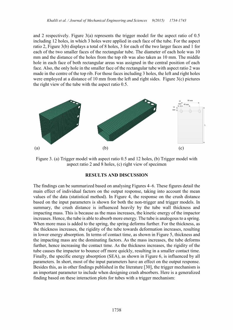
and 2 respectively. Figure 3(a) represents the trigger model for the aspect ratio of 0.5
including 12 holes, in which 3 holes were applied in each face of the tube. For the aspect
ratio 2, Figure 3(b) displays a total of 8 holes, 3 for each of the two larger faces and 1 for
each of the two smaller faces of the rectangular tube. The diameter of each hole was 10
mm and the distance of the holes from the top rib was also taken as 10 mm. The middle
hole in each face of both rectangular areas was assigned in the central position of each
face. Also, the only hole in the smaller face of the rectangular tube with aspect ratio 2 was
made in the centre of the top rib. For those faces including 3 holes, the left and right holes
were employed at a distance of 10 mm from the left and right sides. Figure 3(c) pictures
the right view of the tube with the aspect ratio 0.5.
10
mm
L
10
mm 40 mm
80 mm
(a) (b) (c)
Figure 3. (a) Trigger model with aspect ratio 0.5 and 12 holes, (b) Trigger model with
aspect ratio 2 and 8 holes, (c) right view of specimen
RESULTS AND DISCUSSION
The findings can be summarized based on analysing Figures 4–6. These figures detail the
main effect of individual factors on the output response, taking into account the mean
values of the data (statistical method). In Figure 4, the response on the crush distance
based on the input parameters is shown for both the non-trigger and trigger models. In
summary, the crush distance is influenced heavily by the tube wall thickness and
impacting mass. This is because as the mass increases, the kinetic energy of the impactor
increases. Hence, the tube is able to absorb more energy. The tube is analogous to a spring.
When more mass is added to the spring, the spring deforms further. For the thickness, as
the thickness increases, the rigidity of the tube towards deformation increases, resulting
in lower energy absorption. In terms of contact time, as shown in Figure 5, thickness and
the impacting mass are the dominating factors. As the mass increases, the tube deforms
further, hence increasing the contact time. As the thickness increases, the rigidity of the
tube causes the impactor to bounce off more quickly, resulting in a smaller contact time.
Finally, the specific energy absorption (SEA), as shown in Figure 6, is influenced by all
parameters. In short, most of the input parameters have an effect on the output response.
Besides this, as in other findings published in the literature [30], the trigger mechanism is
an important parameter to include when designing crash absorbers. Here is a generalized
finding based on these interaction plots for tubes with a trigger mechanism:

Energy absorption capability of thin-walled aluminium tubes under crash loading
1739
Table 3. Design of Experiment detailing the various design variables.
Tubes Models L
(mm)
Aspect
ratio
Wall thickness, t
(mm)
Friction
coefficient
V
(m/s)
M
(kg)
Non-
triggers
R-02 150 0.5 1 0.1 15 10
R-14 150 0.5 3 0.5 15 5
R-26 150 0.5 3 0.1 15 10
R-34 150 0.5 1 0.5 15 5
R-44 150 0.5 1 0.1 15 5
R-8 150 2 3 0.5 15 10
R-16 150 2 1 0.1 15 5
R-18 150 2 1 0.5 15 10
R-29 150 2 3 0.1 15 10
R-3 200 0.5 1 0.1 15 10
R-9 200 0.5 3 0.5 15 10
R-19 200 0.5 3 0.1 15 10
R-27 200 0.5 1 0.5 15 5
R-30 200 0.5 3 0.5 15 5
R-39 200 0.5 3 0.1 15 5
R-4 200 2 1 0.1 15 10
R-5 200 2 3 0.1 15 10
R-6 200 2 3 0.5 15 5
R-10 200 2 1 0.5 15 10
R-11 200 2 3 0.1 15 5
R-20 200 2 1 0.5 15 5
Triggers
R-01 150 0.5 1 0.5 15 10
R-33 150 0.5 3 0.5 15 10
R-42 150 0.5 3 0.5 15 5
R-47 150 0.5 3 0.1 15 5
R-48 150 0.5 1 0.1 15 5
R-13 150 2 3 0.5 15 10
R-25 150 2 1 0.1 15 10
R-32 150 2 3 0.1 15 5
R-46 150 2 1 0.1 15 5
R-15 200 0.5 1 0.5 15 10
R-17 200 0.5 3 0.1 15 10
R-24 200 0.5 1 0.5 15 5
R-35 200 0.5 1 0.1 15 10
R-45 200 0.5 1 0.1 15 5
R-07 200 2 3 0.5 15 10
R-12 200 2 3 0.5 15 5
R-21 200 2 3 0.1 15 5
R-28 200 2 1 0.1 15 10
R-31 200 2 1 0.5 15 5

Khalili et al. / Journal of Mechanical Engineering and Sciences 9(2015) 1734-1743
1740
(a) (b)
Figure 4. Main effects plot for crush distance response for: (a) no trigger, (b) with
trigger.
(a) (b)
Figure 5. Main effects plot for contact time response for: (a) no trigger (b) with trigger.
(a) (b)
Figure 6. Main effects plot for SEA response for: (a) no trigger (b) with trigger.
To improve the crush distance, crush time and SEA, the tube’s length and aspect
ratio have to be increased. This is also achievable by reducing the wall thickness. On the

Energy absorption capability of thin-walled aluminium tubes under crash loading
1741
other hand, to reduce the peak force, the length and aspect ratio should be increased. This
is also possible by reducing the wall thickness.
CONCLUSIONS
The summary of the results is as follows:
i) The significant outcome is increasing the SEA in the trigger tubes for both aspect
ratios 0.5 and 2 (that is, introducing 12 and 8 holes as the trigger, respectively)
compared with conventional tubes. The trigger mechanism is designed to control
the energy absorbing capacity for the tubes and also to shape tubular structures
under dynamic loading conditions.
ii) Impact mass affects the maximum crush distance. Increasing the striking mass
causes the crush distance and energy absorption to rise, while no change is shown
in the initial peak force and dynamic loading. This signifies that colliding with a
heavier mass only causes extra deformation, with an insignificant increase in the
peak load.
iii) Increasing the length for conventional tubes does not affect the dynamic loading
and energy absorption capacity for the structures. But, the trend is totally different
for trigger tubes. When a tube with the aspect ratio 0.5 is considered, the shorter
tubes (150 mm) show lower values of dynamic loading, while for the aspect ratio
2 the shorter structures indicate higher dynamic loadings.
Finally, based on the interaction of factors, it can be concluded that a guide for a better
energy absorbing tube should be in the area of increasing the length of the tube and the
aspect ratio, followed by reducing the thickness of the tube.
ACKNOWLEDGMENTS
The authors would like to thanks to Universiti Tenaga Nasional, Malaysia for providing
laboratory facilities and financial support.
REFERENCES
[1] Olabi A-G, Morris E, Hashmi M. Metallic tube type energy absorbers: a synopsis.
Thin-Walled Structures. 2007;45:706-26.
[2] Deb A, Mahendrakumar M, Chavan C, Karve J, Blankenburg D, Storen S. Design
of an aluminium-based vehicle platform for front impact safety. International
Journal of Impact Engineering. 2004;30:1055-79.
[3] Yamashita M, Kenmotsu H, Hattori T. Dynamic axial compression of aluminum
hollow tubes with hat cross-section and buckling initiator using inertia force
during impact. Thin-Walled Structures. 2012;50:37-44.
[4] Jensen Ø, Langseth M, Hopperstad O. Experimental investigations on the
behaviour of short to long square aluminium tubes subjected to axial loading.
International Journal of Impact Engineering. 2004;30:973-1003.
[5] Rossi A, Fawaz Z, Behdinan K. Numerical simulation of the axial collapse of thin-
walled polygonal section tubes. Thin-walled structures. 2005;43:1646-61.
[6] Gupta N, Sheriff NM, Velmurugan R. Analysis of collapse behaviour of combined
geometry metallic shells under axial impact. International Journal of Impact
Engineering. 2008;35:731-41.

Khalili et al. / Journal of Mechanical Engineering and Sciences 9(2015) 1734-1743
1742
[7] Al Galib D, Limam A. Experimental and numerical investigation of static and
dynamic axial crushing of circular aluminum tubes. Thin-Walled Structures.
2004;42:1103-37.
[8] Lee S, Hahn C, Rhee M, Oh J-E. Effect of triggering on the energy absorption
capacity of axially compressed aluminum tubes. Materials & Design. 1999;20:31-
40.
[9] Niknejad A, Abedi MM, Liaghat GH, Nejad MZ. Prediction of the mean folding
force during the axial compression in foam-filled grooved tubes by theoretical
analysis. Materials & Design. 2012;37:144-51.
[10] Zhang X, Huh H. Energy absorption of longitudinally grooved square tubes under
axial compression. Thin-Walled Structures. 2009;47:1469-77.
[11] Zhang X, Tian Q, Yu T. Axial crushing of circular tubes with buckling initiators.
Thin-Walled Structures. 2009;47:788-97.
[12] Chen D, Ozaki S. Circumferential strain concentration in axial crushing of
cylindrical and square tubes with corrugated surfaces. Thin-Walled Structures.
2009;47:547-54.
[13] Ghamarian A, Abadi MT. Axial crushing analysis of end-capped circular tubes.
Thin-Walled Structures. 2011;49:743-52.
[14] Yamashita M, Kenmotsu H, Hattori T. Dynamic crush behavior of adhesive-
bonded aluminum tubular structure—Experiment and numerical simulation. Thin-
Walled Structures. 2013;69:45-53.
[15] Langseth M, Hopperstad O, Berstad T. Crashworthiness of aluminium extrusions:
validation of numerical simulation, effect of mass ratio and impact velocity.
International Journal of Impact Engineering. 1999;22:829-54.
[16] Alghamdi A, Aljawi A, Abu-Mansour T-N. Modes of axial collapse of
unconstrained capped frusta. International Journal of Mechanical Sciences.
2002;44:1145-61.
[17] Salehghaffari S, Tajdari M, Panahi M, Mokhtarnezhad F. Attempts to improve
energy absorption characteristics of circular metal tubes subjected to axial
loading. Thin-Walled Structures. 2010;48:379-90.
[18] Bambach M. Axial capacity and crushing behavior of metal–fiber square tubes–
Steel, stainless steel and aluminum with CFRP. Composites Part B: Engineering.
2010;41:550-9.
[19] Hong W, Jin F, Zhou J, Xia Z, Xu Y, Yang L, et al. Quasi-static axial compression
of triangular steel tubes. Thin-Walled Structures. 2013;62:10-7.
[20] Mamalis A, Manolakos D, Ioannidis M, Chronopoulos D, Kostazos P. On the
crashworthiness of composite rectangular thin-walled tubes internally reinforced
with aluminium or polymeric foams: Experimental and numerical simulation.
Composite Structures. 2009;89:416-23.
[21] Kashani MH, Alavijeh HS, Akbarshahi H, Shakeri M. Bitubular square tubes with
different arrangements under quasi-static axial compression loading. Materials &
Design. 2013;51:1095-103.
[22] Zhang X, Cheng G, You Z, Zhang H. Energy absorption of axially compressed
thin-walled square tubes with patterns. Thin-Walled Structures. 2007;45:737-46.
[23] Zhang X, Huh H. Crushing analysis of polygonal columns and angle elements.
International Journal of Impact Engineering. 2010;37:441-51.
[24] Li Z, Yu J, Guo L. Deformation and energy absorption of aluminum foam-filled
tubes subjected to oblique loading. International Journal of Mechanical Sciences.
2012;54:48-56.

Energy absorption capability of thin-walled aluminium tubes under crash loading
1743
[25] Gameiro C, Cirne J. Dynamic axial crushing of short to long circular aluminium
tubes with agglomerate cork filler. International Journal of Mechanical Sciences.
2007;49:1029-37.
[26] Tarlochan F, Samer F, Hamouda A, Ramesh S, Khalid K. Design of thin wall
structures for energy absorption applications: Enhancement of crashworthiness
due to axial and oblique impact forces. Thin-Walled Structures. 2013;71:7-17.
[27] Ahmad Z, Thambiratnam DP. Dynamic computer simulation and energy
absorption of foam-filled conical tubes under axial impact loading. Computers &
Structures. 2009;87:186-97.
[28] Theobald M, Nurick G. Experimental and numerical analysis of tube-core
claddings under blast loads. International Journal of Impact Engineering.
2010;37:333-48.
[29] Karagiozova D, Jones N. Dynamic buckling of elastic–plastic square tubes under
axial impact—II: structural response. International Journal of Impact Engineering.
2004;30:167-92.
[30] Najafi A, Rais-Rohani M. Influence of cross-sectional geometry on crush
characteristics of multi-cell prismatic columns. Proceedings of the 49th
AIAA/ASME/ASCE/AHS/ASC Structures, Structural Dynamics and Materials
Conference; 2008.