1. equipment for mechanical installation - swm pave of mechanically installed interlocking concrete...
TRANSCRIPT

ICPI Tech Spec 11 Page 2
2. The shape of the paver and configuration of the laying pattern.
3. Careful job planning by the contractor with support from the manufacturer before the job begins.
4. Systematic and efficient execution of the installation on the job site.As of 2003, ICPI has released Tech Spec 15—A Guide for
Construction of Mechanically Installed Interlocking Concrete Pavements. The guide is intended for large, mechanically installed projects and is for facility owners, design profes-sionals, contractors, and manufacturers. It provides require-ments for quality control of materials and their installation, including bedding sand and pavers. It includes a Quality Control Plan jointly developed and implemented by the paver installation contractor, the paver manufacturer and the general contractor. The specification guide facilitates planning and coordination among these entities, and it supports a systematic approach to manufacture, delivery, installation, and inspection.
1. Equipment for Mechanical InstallationMechanized equipment includes an operator-activated clamp that lifts one layer or cluster of pavers at a time. Each layer can consist of 20 to 72 paving units. The pavers are manufactured in their prescribed laying pattern within the layer. In rare cases, two smaller layers are manufactured and combined in the factory to make one large layer. Layers are packaged in a “cube,” i.e., each layer typically stacked 8 to 10 units high. The cubes arrive at the site with each layer ready to be lifted by the mechanical equipment and placed on the screeded bedding sand. Figure 2 shows a cube of pavers opened and ready for installation by mechanical equipment. When grasped by the clamp, the pavers remain together in the layer. They interlock from lateral pressure provided by the clamp while being lifted.
Each layer or cluster is typically about a square yard (m2) in area. The exact layer area varies with each paver pat-tern. The area covered by the layer can be provided by the manufacturer.
Figure 3. Motorized equipment with a mechanical clamp. Figure 4. Hydraulic clamp picking up layer of pavers
Figure 5. Motorized equipment with a hydraulic clamp. Figure 6. The vacuum head over the paver layer.

ICPI Tech Spec 11 Page 3
Types of Equipment—Mechanized installation equip-ment may be either non-motorized or motorized. Hower, non-motorized equipment, consisting of a wheeled hand cart and clamp that grabs a half layer, or about 15 to 20 pav-ers, is rarely used in North America. While it is not as efficient as motorized equipment, a hand-held cart can save time and strain on the installation crew. Non-motorized equip-ment may be useful on jobs where noise from vehicles is not permitted (e.g., hospitals), or places with weight limitations and very limited working space, such as roofs.
Most motorized equipment prevalent in North America is no heavier than a small automobile and is almost as quiet while operating. This equipment can use three different kinds of clamps for placing concrete pavers. The first type is a mechanical clamp shown in Figure 3 (7). This clamp consists of many levers that are adjusted to conform to the dimen-sions of the paver layer prior to starting the job. The initial adjustment of the clamp ensures a tight fit against the layer
when activated. When the clamp closes and picks up the layer, the movement in the levers compensates for possible slight misalignment of pavers. Misalignment can be from minor dimensional differences among the pavers in the layer, or caused by small bits of dirt that occasionally lodge between them.
When activated by the machine operator, the clamp levers close in unison to pick up a layer. The clamp tightens against its sides while being lifted. The operator then aligns the layer next to the other pavers on the bedding sand. The layer is released from the clamp when almost touching the bedding sand. The layer should not be allowed to gouge the bedding sand as this unevenness will eventually be reflect-ed in the surface of the pavers.
The second type of clamp is hydraulic, i.e., activated by hydraulic pistons that grab the sides of the paver layer as shown in Figure 4 and 5. Prior to starting a job, the hydraulic clamps are adjusted to conform to the configuration of the
45o Herringbone
Figure 7. Paver layer categories for mechanical installation. These are representations of many available patterns.

ICPI Tech Spec 11 Page 4
layer to be placed. The pressure of the hydraulic fluid is ad-justed as well, so that each clamp tightly fits onto the sides of the layer.
The clamps close on the sides of the layer when trig-gered by the operator. The clamps have flexible spring steel grippers on them that compensate for minor size differ-ences or debris among the pavers. As with the mechanical clamp, each layer is grabbed, positioned, the clamp opened, and the pavers dropped a short distance onto the bedding sand. The minimum paver thickness that can be laid with hydraulic or mechanical clamps is 23/8 in. (60 mm).
The third kind of clamp consists of a metal head that covers the paver layer and applies a vacuum. The head has many rubber cups arranged in the paver pattern to be placed. Each cup has a hose attached to it. A vacuum is pulled through the hoses to lift and place all pavers si-multaneously as shown in Figure 6. The machine operator controls the vacuum in the cups that lifts and releases the pavers. This installation equipment tends to be heavier than the other kinds of motorized installation machines.
Vacuum equipment relies on suction to lift the pavers. No particles should be on the surface of the pavers because they will interfere with the seal between the cups and the paver surfaces. For different laying patterns, the arrange-ment of the cups on the head must be adjusted or new ones used. Vacuum equipment for installing interlocking con-crete pavers is not prevalent in North America. Similar kinds of vacuum equipment are more commonly used to place larger concrete paving slabs ranging in size from 12 x 12 in. (300 x 300 mm) up to 36 x 36 in. (900 x 900 mm).
2. Pavers for Mechanical InstallationThere are four general categories of paver patterns used as layers. They are running bond, cross joint bond, herringbone, and special designs for mechanical installation only. Figure 7 illustrates these types of patterns. These will be referenced in the discussion below.
On some mechanical jobs in a few developing countries, pavers are manufactured and manually arranged in the factory into the laying pattern for installation by machine. While this method may create needed jobs in some regions
of the world, high labor costs prohibit this approach in North America. Pavers should be molded in the final laying pattern in order to maximize efficiency and control costs. The following criteria should be used in evaluat-ing mold/layer configurations for efficiency, cost, and performance.
Utilization of the manufacturing pal-let—The size of the production machine governs the size of the mold and hence the total number of pavers in each layer. Molds for mechanical installation should be as large as possible and should utilize the available space efficiently to maximize cost-effectiveness. For example, the difference between 35 and 45 pavers in a layer means a 28% increase in the number of pavers placed with the same effort and time.
The contractor can enhance the op-portunity for cost-effective installations by
reviewing mold layouts with the paver manu-
Figure 8. Clamps are an efficient method of moving cubes of pavers around the site, and can eliminate the need for wooden pallets.
Hand-laid Areas
Offset or Staggered Layer
Figure 9. Staggered installation of clusters (8).

ICPI Tech Spec 11 Page 5
facturer for the most efficient use of pavers. The layouts present varying efficiencies in packaging, shipment, and transfer of material on the site, as well as supplemental manual installation, half pavers, bond pat-terns, interlock, and use of spacer bars.
Packaging and shipment—Pavers are banded as cubes for shipment with steel and/or plastic straps. The layer configuration should enable each cube to be tightly banded with strapping; otherwise the pavers may shift during shipping, especially when the distance from the factory to the site is great. Misaligned pavers on the cube may need to be realigned on the job site prior to placing them. Realignment with installation equipment will waste time on the job site.
Most manufacturers can provide cubes of pavers tightly banded horizontally and vertically to minimize shifting while in transit. Plastic wrap is often applied as shrink wrap or stretch wrap (stretched tightly in many layers). All packaging is removed from the cubes when they are positioned near the laying face (or edge) of the pavement.
Transfer on the site—Most layer configurations enable their transfer (packaged as cubes) around the site with fork lifts or clamps. Cubes of pavers may be moved with or with-out wooden pallets.
They enable transfer with fork lifts but pallets incur additional costs in handling time and charges. Mechanical clamps specifically made for transferring paver cubes can eliminate the need for pallets on the site, thereby reducing material and labor costs (see Figure 8). If pavers are deliv-ered without pallets and no clamps are available on the site, then the contractor may supply pallets on which to place the cubes for locating them at the laying face of the job with a forklift.
Supplemental manual installation—The amount of supplemental manual installation on a mechanically placed job depends on two factors. First, some areas must be
placed only by hand because of the configu-ration of the site. They can’t be reached by a machine, or the layer is too large for the area to be paved. Such areas may include those around light fixtures, utility structures, and drainage inlets.
Second, some patterns may need to be offset by a course or two when placed. In this case, the initial area of the pavers must be placed by hand. The hand-laid areas establish an offset for the coursing and the direction of the subsequent, machine-installed layers. Some herringbone patterns require an off-set, and some special designs for mechanical installation may need to be offset to stagger the layers. For example, Figure 9 shows hand-laid areas that start a staggered pattern for the remaining machine-set layers.
Half pavers or half stones—Mechani-
Figure 10. Half pavers to be removed from herringbone layers and filled with whole units. Gray spaces are filled with whole pavers as well.
Figure 11. Removal of half pavers and installation of whole units.

ICPI Tech Spec 11 Page 6
cal placement of some herringbone patterns requires half units. These minimize shifting of layers during transport and facilitate a firm grip by the clamp as it grabs each layer. When placed mechanically, herringbone laying patterns require hand removal of half pavers (nominally 4 x 4 in. or 100 x 100 mm in size) on their perimeter. As work proceeds, the removed half pavers are replaced with full-size pavers to create or stitch a pattern that continuously interlocks with no indication of layer or cluster lines. Depending on the layer configuration, two to four half units per layer may need to be removed by hand prior to placing full size units
in the openings. (See Figure 10.)Removal of half pavers is typically done by hand or with
a paver extractor. However, they must be removed and replaced with whole units before the pavers are compacted. (See Figure 11.)
Herringbone patterns provide a high degree of interlock. However, a significant cost could be incurred from remov-ing, collecting, and disposing of the half units. Therefore, installation of these patterns can generate waste material and labor costs higher than other laying patterns.
One way to reduce the waste material and extra labor required for herringbone patterns is by having them made without half units. When packaged as cubes, the vertical, half paver openings on their sides may be filled with wood or plastic pipe for the layers to remain stable during ship-ment. The wood or pipes are removed when each cube is opened at the site. When each layer is installed, full-sized pavers still must be placed in the openings between the lay-ers. Figure 12 shows a herringbone pattern with an offset but with no half pavers.
Bond pattern—Likewise, cross bond and running bond patterns generally do not require an offset area laid by hand. If laid end-to-end, the openings created by running bond patterns may require filling the openings with concrete pav-ers. Rather than trying to mesh or key the layers into each other, a more efficient method is to butt the ends of the run-ning bond pattern and drop in filler pavers by hand.
A running bond pattern with rectangular shaped units can be manufactured in a stack bond (all joints aligned) and the vertical joints shifted one-half unit on the job site. This can
Figure 12. Herringbone pattern with no offset or half pavers.
Figure 13. Spacer bars on the sides of concrete pavers are essential for mechanical installation.
ICPI Tech Spec 11 Page 7
be done with mechanical and hydraulic clamps. Some shaped pavers can be made in stack bond patterns and shifted to run-ning bond by some machines. Besides bond patterns, basket weave patterns can be installed mechanically. Concrete grid pavements can be mechanically installed as well. They are typically placed in a stack, running, or modified bond pattern as shown in Figure 7.
Cross joint bond patterns are designed with no half units to be removed by hand, thereby increasing installation effi-ciency. Proprietary and non-proprietary patterns have been developed for mechanical installation with no half stones. These have a herringbone-like pattern, and may or may not have completely interlocking patterns from one layer to the next. These patterns install quickly.
Interlock among layers—Most layers and patterns pro-vide a continuous interlocking surface of pavers. Horizontal interlock and the pavement structure are further enhanced by patterns that continuously interlock with their neighbors (9). Others are placed in clusters whose patterns do not interlock from one layer to the next. These kinds of patterns can be offset by a half layer to increase interlock.
Spacer bars—Pavers should have spacer bars or nibs on their sides for mechanical installation. The nibs generally protrude no more than 1/16 in. (2 mm) from the sides of the paver. (See Figure 13.) Spacer bars maintain a minimum joint width between the pavers, especially while the units are grabbed by the clamp and placed on the bedding sand. The space allows joint sand to enter and reduces the likelihood of edge spalling should there be local settlement. Some kinds of permeable interlocking concrete pavers have spacer bars between 3/16 to 1/8 (5 and 30 mm) to encourage infiltra-tion of stormwater. Most of these concrete pavers can be installed mechanically.
Spacer bars are recommended that extend the full height of the paver, i.e., from bottom to the top. Installation of 23/8 in. (60 mm) thick pavers with mechanical or hydraulic equipment is facilitated when spacer nibs extend the full height of the paver. Others, called “blind” spacers, extend from the bottom to within 3/16 to 1 in. (5 to 25 mm) at the top of the paver so they aren't visible from the surface. They may be tapered at the top as well. These kinds of spacers are not recommended for mechanical installation.
3. Job PlanningDesign considerations—Once a laying pattern is selected, coordination between the designer and the contractor when developing the project drawings can save time and costs. One way to save costs is to minimize cutting of pavers along the edges. For some patterns, this is accomplished by using edge pavers to start or close the pattern. Patterns without edge units may begin along an edge that requires little or no cutting of pavers.
Another cost-saving construction detail is surrounding bollards, water valves, gas valves, manholes, light standards, etc., with a concrete collar. The collars should be of sufficient durability and shape to withstand anticipated loads and climate. Square collars are preferred over round ones be-cause they provide a straight surface against which a string course of pavers is placed. A string course around collars will provide additional stability and better appearance when cut pavers are placed against the course. ICPI Tech Spec 3—Edge Restraints for Interlocking Concrete Pavements provides ad-ditional information on this construction detail.
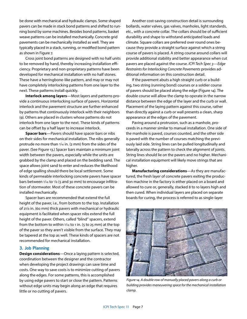
If the pavement abuts a high straight curb or a build-ing, two string (running bond) courses or a soldier course of pavers should be placed along the edge (Figure 14). The double course will allow the clamp to operate in the narrow distance between the edge of the layer and the curb or wall. Placement of the laying pattern against this course, rather than directly against a curb or wall presents a clean, sharp appearance at the edges of the pavement.
Paving around a protrusion, such as a manhole, pro-ceeds in a manner similar to manual installation. One side of the manhole is paved, courses counted, and the other side is paved with the number of courses matching the previ-ously laid side. String lines can be pulled longitudinally and laterally across the pattern to check the alignment of joints. String lines should lie on the pavers and no higher. Mechani-cal installation equipment will likely move strings that are higher.
Manufacturing considerations—As they are manufac-tured, the fresh layer of concrete pavers exiting the produc-tion machine in the factory is either placed on a board and allowed to cure or, generally, stacked 8 to 10 layers high and then cured. When individual layers are placed on separate boards for curing, the process is referred to as single-layer
Figure 14. A double row of manually placed pavers along a curb or building provides maneuvering space for the mechanical installation clamp.

ICPI Tech Spec 11 Page 8
production. The individual layers are allowed to harden for a day and then are stacked and strapped for shipping. If lay-ers are stacked to make a cube while the concrete is fresh, the manufacturing process is called multi-layer production. The fresh cube of pavers is allowed to harden and then is strapped for shipping.
Pavers made on a multi-layer machine should have a suf-ficient amount of sand spread on each layer as it is manu-factured. This prevents layers from sticking to each other while curing. It will also prevent them from sticking when a mechanical installation clamp lifts a layer on the job site. Sand between the layers will avoid delays from detaching stuck pavers with a mallet and eliminates the risk of drop-
ping the entire layer from the machine clamp.Manufacturing boards for single-layer production
should be smooth so that they don't leave rough edges on the bottom of the concrete pavers. This will avoid minor chipping of their edges during transit and bits of concrete dropping into the cube. The absence of small pieces of concrete will eliminate interference with joint spacing and difficulties with clamping each layer by the installation machine.
Storage and flow of materials on the site—A place to store inbound concrete pavers should be identified as part of planning each project. This location may change as the paving progresses. For example, pavers may be stored on the construction site at the beginning of the job. As more paving is placed, incoming pavers can be stored directly on the paved area. Time savings are maximized when inbound loads of concrete pavers are unloaded once and moved once to the laying face.
The rate of paver delivery to the job site should be coordinated between the contractor and supplier. Too many pavers may crowd the site and slow productivity. Likewise, an insufficient rate of pavers being delivered can keep crews waiting. Time is saved by identifying places for storage on the site before the job develops and by ordering delivery of a specified number of truckloads or cubes of pavers each day. A staging area may be used to receive the delivered pavers and store them until they are ready to be brought to the laying face.
When cubes are moved from a delivery truck and stored in a staging area, they should be placed on level ground. If they are placed on uneven ground, the layers may shift and become uneven. A great amount of shifting will make clamping each layer by the installation machine difficult or impossible in extreme cases.
Cubes are usually moved from the delivery truck to the staging area or directly to the laying face by a clamp truck or a fork lift truck. When located in a staging area cubes should be spaced apart so that the clamps trucks can lift them.
When cubes are delivered near the laying face, they are usually spaced so that the installation machine operator can grab layers from each cube with the least amount of movement. A cube with eight layers will be placed in four to seven minutes, depending on the skill of the operator and the placement of the cubes. As the layers are placed on the bedding sand, a crew member brings more cubes forward to the laying face. The area between the cubes should ap-proximate the area that the cube will cover when placed (Figure 15).
Orientation of the laying pattern—Depending on the pattern, some paver layers can be placed on the bedding sand in only one or two directions. Therefore, the orienta-tion of the cubes on the site with respect to the direction
Figure 15. Spacing of cubes at the laying face is determined by how much area will be covered by each, as well as by the clearance required by the machine clamp. Orientation of the cubes follows the direction of paving.
Figure 16. A simple gauge for checking dimensional tolerances on the job site.

ICPI Tech Spec 11 Page 9
of paving will affect efficiency. Obviously, the cubes should be moved as little as possible once they reach the site. Their location and orientation will need to be determined before starting the job. They should to be communicated to those responsible for moving the cubes on the site. This will avoid wasted time from the installation machine making addi-tional motions or from moving the cubes into the proper position. Crew members should be informed on placement and spacing cubes as part of planning the job.
4. Systematic and Efficient ExecutionDimensional tolerances—The dimensional tolerances should be smaller than those stated for length and width in ASTM or CSA standards for concrete pavers, i.e., + 1/16 in. or +1.6 mm. These standards allow for slight growth dimensions as manufacturing of the job progresses (10, 11). This is due to wear on the manufacturing mold from the production process. If not managed, layers will become increasingly difficult to place into the pattern. This will slow crew production as the layers will require adjustment with mallets and pry bars to accept new layers next to them. Expe-rience and computer modelling has shown that pavers will install more rapidly when growth in overall length and width dimen-sions are kept under 1 mm.
In addition, straight lines and consistent joint widths will be increasingly difficult to maintain. Because pavers are enlarging slight-ly, joint widths enlarge and joint lines will be impossible to keep straight while attempt-ing to wedge the pavers between layers. Wider joints result in a loss of interlock which
may reduce the structural integrity and stability of the pavement surface. Therefore, consistent paver dimensions throughout the job helps the crew work efficiently by maintaining straight lines, uniform joint widths, while contributing to interlock.
Dimensional growth of pavers is managed by periodically changing molds during manufacturing. This will enable pavers to enlarge consistently while staying within specified toler-ances. The number of cycles a mold can run prior to changing will depend on its quality and the abrasiveness of the concrete mix. Dimensional growth is also managed by periodically checking the paver dimensions. This distribution
can be done with a ruler, template, or a gauge. An example of a gauge is shown in Figure 16.
Dimensional growth is further managed by unloading and installing the largest pavers first. However, loads would need to be marked and distributed on the site in the order of production. This distribution may not be possible on some jobs.
Pavers should have straight, square sides to ensure a secure grip by mechanical or hydraulic clamps. Pavers with bulged or slightly rounded, “bellied” sides can drop while being held by these clamps (12). Furthermore, straight lines and consistent joint widths cannot be maintained and in-terlock decreases. Bulged sides usually result from excessive water in the concrete mix.
Figure 18. An asphalt spreading machine is modified to evenly and rapidly spread bedding sand.
Figure 17. Powered screed bucket accelerates spreading of bedding sand. The width of the bucket can be adjusted.
ICPI Tech Spec 11 Page 10
Establishing lines—Job site con-figuration determines the starting point for mechanical installation. Prior to starting, a string line is pulled or chalk line snapped on the screeded bedding sand. The line is perpendicular to the starting face (which may be a curb if it is square to the line) and several layers are placed on the line to establish straight and square courses of layers. Align-ing the layers and joint lines at the beginning of the laying process is essential to keeping joints tight and the pattern “in square” as the job proceeds. The lines can guide manual installation of the starting courses (if re-quired) as well as mechanical laying. Parallel string lines are pulled and spaced at inter-vals equal to several paver layer widths. The distance between string lines should repre-sent the maximum width of the paver layers, i.e., taking into account growth in the layer width from mold wear. The allowable growth, and means of measurement of layers, should be agreed upon between the manufacturer and installer prior to laying the pavers.
Bedding sand—Besides a consistent flow of pavers, there must be a sufficient area of bedding sand screeded and ready to receive the pavers. An oversize area will not get filled with pavers by the end of the day. A small area will
fill rapidly, and the crew must work quickly to prepare more screeded sand. The optimum area to screed depends on the productivity of the machine operator and the continuous flow of pavers. This area is different for each project.
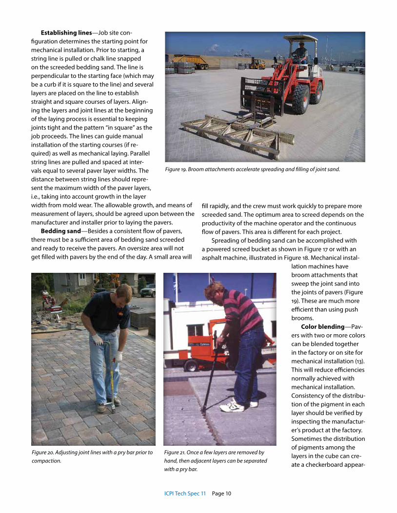
Spreading of bedding sand can be accomplished with a powered screed bucket as shown in Figure 17 or with an asphalt machine, illustrated in Figure 18. Mechanical instal-
lation machines have broom attachments that sweep the joint sand into the joints of pavers (Figure 19). These are much more efficient than using push brooms.
Color blending—Pav-ers with two or more colors can be blended together in the factory or on site for mechanical installation (13). This will reduce efficiencies normally achieved with mechanical installation. Consistency of the distribu-tion of the pigment in each layer should be verified by inspecting the manufactur-er’s product at the factory. Sometimes the distribution of pigments among the layers in the cube can cre-ate a checkerboard appear-
Figure 19. Broom attachments accelerate spreading and filling of joint sand.
Figure 20. Adjusting joint lines with a pry bar prior to compaction.
Figure 21. Once a few layers are removed by hand, then adjacent layers can be separated with a pry bar.

ICPI Tech Spec 11 Page 11
ance when the layers are placed. However, concrete pavers made with only one color should not create a checkered ap-pearance when installed. This can be minimized by installing from two or three cubes at a time. There may be slight color variations from layer to layer due to the nature of concrete.
Installation crews—Crew sizes and assignments will vary among contractors. A typical crew for mechanical installation is two to five persons. It consists of the machine operator and a helper at the clamp. An additional person is needed at the clamp if the pattern requires that whole pavers be placed between layers for a continuous interlock-ing pattern. Three or four crew members spread and screed sand, bring cubes to the laying face with a lift truck, cut and fill in units along the edges, and compact the pavers.
Clamping, lifting, and placing of pavers are executed as a continuous motion of the machine to maximize produc-tivity. Excess travel of the machine is minimized by placing cubes close to the laying face. The cubes are spaced so that as one cube covers an area, the machine moves easily to the next cube for placing. The machine operator works in a small area supported by a crew that keeps machine travel to a minimum.
The helper at the laying face adjusts the clamp’s posi-tion before each layer is released onto the bedding sand. The helper removes half pavers and places full-sized pavers as required. He also aligns the pavers with a rubber mallet, making sure that the joints widths are tight and consistent. The alignment of joints and lines is checked by the helper and machine operator using observation by eyesight, string lines, and a transit as the job progresses. Due to the speed at which pavers are mechanically placed, checks should be made with string lines every 20 to 40 ft (6 to 13 m) of paved distance. Joint lines may require adjustment with a pry bar in order to maintain straight lines. See Figure 20.
Project specifications for joint widths should be followed with the contractor straightening uneven jointlines and clos-ing excessively wide joint spaces. While not possible on some jobs, installation of pavers in the order in which they were made enables the contractor to save time and avoid wedging layers of different dimensions between others. Widened joints and uneven joint lines will be reduced as well.
The crew rotates jobs among spreading and screeding the bedding sand ahead of the machine(s), moving cubes into place, removing and neatly storing steel straps and wooden pallets (if used) from the job site, cutting, com-pacting, spreading joint sand, sweeping, and compacting the pavers behind the installation machine(s). The crew rotates jobs so that no one is fatigued by doing one job continuously.
Any movement of heavy trucks and forklifts should be avoided on a paved area in which units are not yet compact-
ed, joints not filled and compacted again. This will prevent creeping, lipping, breaking or rutting of the surface of the pavement. The pavers should be compacted, joints filled with sand, and recompacted at the end of each day within 6 ft (2 m) of the laying face.
Average productivity per machine and crew including screeding bedding sand, placing, and compacting pavers can be between 3,000 sf (300 m2) and 6,000 sf (600 m2) per eight-hour day (1) (3) (4) (14). Keys to high productivity are pre-job planning among the contractor and material sup-pliers, as well as high quality pavers. They include careful coordination of deliveries, regulated flow of materials onto the site, and crew members who know their tasks. By careful planning, saving even 15 seconds per layer translates into saving many labor hours. For example, a 100,000 sf (10,000 m2) project may involve placing 10,000 layers. Saving 15 seconds per layer saves 42 labor hours.
Mechanical installation may be appropriate for some jobs and not for others. Naturally, the experience of the foreman and crew will influence productivity. Experienced contractors document productivity and labor costs for mechanical and manual installation through a job costing system. Comparisons of previous job costs between the two installation methods will help indicate whether a proposed job should be placed manually or mechanically. In some cases, a close project deadline, rather than job costs, may dictate the use of mechanical installation.
Reinstatement with mechanical equipment— ICPI Tech Spec 6—Reinstatement of Interlocking Concrete Pavements provides guidelines for removing and replacing concrete
Figure 22. After the layers are separated they can be grabbed by the machine clamp.

ICPI Tech Spec 11 Page 12
pavers when making repairs to underground utilities. Prior to extracting layers of pavers with mechanical equipment, an area the size of three layers should first be removed by hand. The removed pavers allow space for separating the remaining layers from each other. The remaining layers are separated in group of layers by a few inches (cm) from each other with a pry bar (Figure 21). This slight distance between layers enables the machine clamp to grab each one (Figure 22). The procedure works best on paving patterns other than herringbone with rectangular units. In most cases extract-ing individual layers is only possible if they were originally installed without pavers joining one layer to the next.
As with manual removal of pavers, each layer removed by machine can be stacked near the pavement opening. If the pavers must be moved away from the site, the layers can be stacked on pallets for easier removal. The sides and bot-toms of each layer should be checked for sand sticking to them prior to reinstatement. The sand will often be removed during handling by the machine.
ConclusionWith manual installation, most crew members move between 7 and 10 tons (6.3 and 9 tonnes) of material per day. Mechanical installation requires less physical exertion, thereby reducing fatigue and job related injuries. There are also time and money-saving advantages for the contrac-tor, designer, and project owner. Each project is an exercise in systematic material handling from manufacture to final compaction.
The growth of mechanical installation follows the increased use of concrete pavers in commercial, municipal, port, and airport projects. Owners and designers are encour-aged to contact producer and contractor members of the Interlocking Concrete Pavement Institute experienced in the use of mechanical installation in the early stages of a project. Planning will maximize time and money savings. Other ICPI Tech Spec technical bulletins provide additional information on design and construction vital to constructing successful projects with mechanical equipment.
References1. Van der Heijden, J. H. A., “Mechanical Paving With Concrete Blocks,” in
Proceedings, The Second International Conference on Concrete Block Paving, April 1984, Delft, The Netherlands, pp. 230-237.
2. Koningsveld, E. A. P, “The Improvement of the Working Condition of Paviours by Means of Mechanisation.” in Proceedings, Third International Conference on Concrete Block Paving, Rome, Italy, May 1998, Pavitalia, pp. 418-420.
3. Vievermans, S. J. A., “Continued Application of Mechanical Paving in Rotterdam,” in Proceedings, Third International Conference on Concrete Block Paving, Rome, Italy, May 1988, Pavitalia, pp. 421-428.
4. Krömer, Rupert, “Importance, Demands and Possibilities of a Rational Laying of Concrete Paving Blocks,” Concrete Precasting Plant and Technology, May 1988, Wiesbaden, Germany, pp. 449-453.
5. Lintho K. and Grayston H., “Mechanical Laying of Paving Blocks,” in Proceedings, Second International Workshop on Concrete Block Paving, Oslo, Norway, June 1994, pp. 349-353.
6. Smith, David R., “Restoring Streets with Mechanical Installed Concrete Block Paving,” in Proceedings, Third International Conference on Concrete Block Paving, Rome, Italy, May 1988, Pavitalia, pp. 435442.
7. Walsh, Noel P., “The Next Generation of Mechanically Laying Concrete Block Paving,” in Proceedings, Fifth International Conference on Concrete Block Paving, Tel Aviv, Israel, June 1996, Pave Israel, pp. 193-198.
8. Shackel, B., “Design and Construction of Interlocking Concrete Block Pavements,” Elsevier Applied Science, London, England, 1990, p. 210.
9. Houben, Lambert J. M., “Effect of the Use of Half-Blocks in Mechanical Block Paving,” in Proceedings, Fifth International Conference on Concrete Block Paving, Tel Aviv, Israel, June 1996, Pave Israel, pp. 213-224.
10. Lilley, A., “Size and Block Shape—Do They Matter?” in Proceedings, Second International Workshop on Concrete Block Paving, Oslo, Norway, June 1994, pp. 106-112.
11. Mackisack, M. and Pywell, C., “Managing Block Paver Gap Performance: A Modelling Solution,” in Proceedings, Second International Workshop on Concrete Block Paving, Oslo, Norway, June 1994, pp. 113-120.
12. Probst, Martin, “Mechanical Installation of Concrete Block Pavers” in Proceedings, Third International Workshop on Concrete Block Paving, Cartagena, Colombia, May 1998, Institute of Colombian Cement Producers, pp. 39-1 to 39-18.
13. Imazu, H. “Multicolored Design Arranging Device (Laying Device) for Mechanical Laying,” in Proceedings, Fifth International Conference on Concrete Block Paving, Tel Aviv, Israel, June 1996, Pave Israel, pp. 199-212.
14. Mujaj, L., “Concrete Block Paving at the New Airport for Hong Kong,” in Proceedings, Third International Workshop on Concrete Block Paving, Cartagena, Colombia, May 1998, Institute of Colombian Cement Producers, pp. 19-1 to 19-14.
The content of ICPI Tech Spec technical bulletins is intended for use only as a guide-line. It is not intended for use or reliance upon as an industry standard, certification or as a specification. ICPI makes no promises, representations or warranties of any kind, expressed or implied, as to the content of the Tech Spec Technical Bulletins and disclaims any liability for damages resulting from the use of Tech Spec Techni-cal Bulletins. Professional assistance should be sought with respect to the design, specifications and construction of each project.
14801 Murdock Street
Suite 230
Chantilly, VA 20151
In Canada:
P.O. Box 1150
Uxbridge, ON L9P 1N4
Canada
Tel: 703.657.6900
Fax: 703.657.6901
E-mail: [email protected]
www.icpi.org