1 eliazar ortiz [email protected] 1 xcs final instrument design review – dco june 18, 2009...
Post on 21-Dec-2015
215 views
TRANSCRIPT

1 Eliazar [email protected]
1XCS Final Instrument Design Review – DCOJune 18, 2009
Diagnostics & Common Optics
LUSI WBS 1.5
Yiping Feng – DCO Lead ScientistEliazar Ortiz – DCO Lead Engineer
DCO Engineering Staff
June 18, 2009

2 Eliazar [email protected]
2XCS Final Instrument Design Review – DCOJune 18, 2009
Acknowledgment
DCO Engineering StaffTim Montagne
Profile/wavefront monitor
Intensity monitor
Intensity-position monitor
Harmonic rejection mirror
Marc CampellAttenuator
X-ray focusing lens
Richard JacksonSlits system
Pulse picker

3 Eliazar [email protected]
3XCS Final Instrument Design Review – DCOJune 18, 2009
Outline
DistributionDiagnostics Status
Profile Monitor Profile-Intensity MonitorIntensity-Position Monitor
Common Optics StatusSlitsAttenuator & Pulse PickerX-Ray Focusing Lens
Cost & ScheduleSummary

4 Eliazar [email protected]
4XCS Final Instrument Design Review – DCOJune 18, 2009
Components Distribution
Components locationsDistributed throughout the XPP, CXI, and XCS instruments, including X-ray transport tunnel
SXR
CXIEndstation
Near Experimental Hall
Far Experimental Hall
X-ray Transport
Tunnel
XCSEndstation
XPPEndstation
AMO
MEE
LCLS X-ray FEL

5 Eliazar [email protected]
5XCS Final Instrument Design Review – DCOJune 18, 2009
Components DistributionDiagnostics/Optics XPP CXI XCS Total
Total Location Total Location Total Location
Profile Monitor 31 in Hutch 2
2 in Hutch 3 (combined with Intensity monitor)
32 in Hutch 5
1 in Hutch 5 (combined with Intensity monitor)
64 in XRT (combined with
Intensity monitor)
2 in Hutch 4 (combined with Intensity monitor)
12
Wavefront Monitor - - 1 Hutch 5 - - 1
Intensity Monitor 2 Hutch 3 (combined with Profile monitor) 1 Hutch 5 (combined with Profile
monitor) 64 in XRT (combined with
profile monitor)
2 in Hutch 4 (combined with Profile monitor)
9
Intensity-Position Monitor 31 in Hutch 2
2 in Hutch 3 2 Hutch 5 64 in XRT
2 in Hutch 4 11
X-Ray Focusing Lenses 1 Hutch 3 2 Hutch 5 1 XRT 4
Slit System 31 double slit system in Hutch 3
1 single slit system in Hutch 3
1 single slit system in Hutch 24 Hutch 5 7
2 double slit systems in XRT
2 single slit systems in XRT
3 single slit systems in Hutch 4
14
Attenuators-Filters 1 Hutch 3 1 XRT 1 Hutch 4 3
Pulse Picker 1 Hutch 3 1 XRT 1 Hutch 4 3
Harmonic Rejection Mirrors 1 Hutch 3 - - 1 Hutch 4 2
Total 15 15 29 59

6 Eliazar [email protected]
6XCS Final Instrument Design Review – DCOJune 18, 2009
DCO Distribution on XCSPhoton Shutter
Primary Slits
Diagnostics
Secondary Slits
Diagnostics
Split and Delay
Focusing Lenses
Attenuators
Diagnostics
Photon Shutter
Defining Slits
Diffractometer
Large AngleDetector Stage
Monochromator
Tran
sp
ort T
un
ne
lF
EH
Hu
tch
4
Harm. Rej. Mirrors
Pulse Picker
Secondary Slits
Diagnostics
Attenuators / Pulse PickerQty 1
Profile Monitor /Intensity MonitorQTY 6
Intensity Position MonitorQty 6
X-Ray Focusing LensQty 1
Harm. Rej. Mirror System *Qty 1
Slits Double ConfigurationQty 2
Slits single ConfigurationQty 5
* A system has two mirrors, one mirror per chamber
7 Eliazar [email protected]
7XCS Final Instrument Design Review – DCOJune 18, 2009
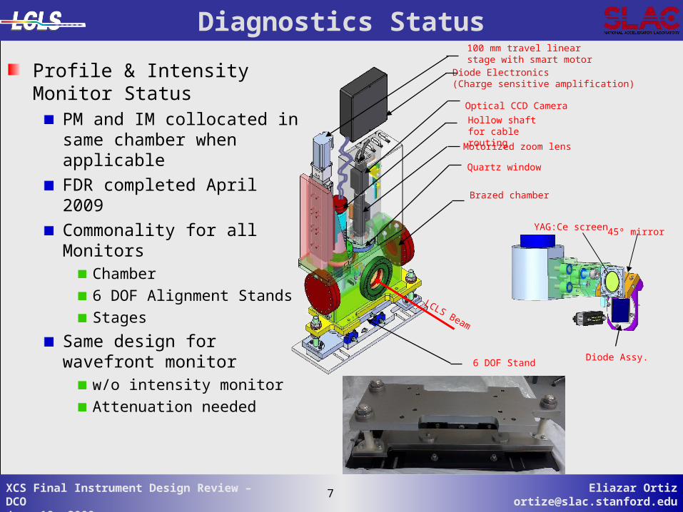
Profile & Intensity Monitor Status
PM and IM collocated in same chamber when applicable
FDR completed April 2009
Commonality for all MonitorsChamber
6 DOF Alignment Stands
Stages
Same design for wavefront monitor
w/o intensity monitor
Attenuation needed
Diagnostics Status
YAG:Ce screen
Diode Assy.
45º mirror
Brazed chamber
6 DOF Stand
Motorized zoom lens
Optical CCD Camera
Diode Electronics(Charge sensitive amplification)
Quartz window
Hollow shaft for cable routing
100 mm travel linear stage with smart motor
LCLS Beam
8 Eliazar [email protected]
8XCS Final Instrument Design Review – DCOJune 18, 2009
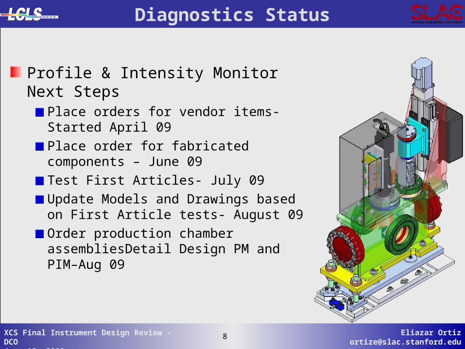
Diagnostics Status
Profile & Intensity Monitor Next StepsPlace orders for vendor items- Started April 09
Place order for fabricated components – June 09
Test First Articles- July 09
Update Models and Drawings based on First Article tests- August 09
Order production chamber assembliesDetail Design PM and PIM–Aug 09
9 Eliazar [email protected]
9XCS Final Instrument Design Review – DCOJune 18, 2009
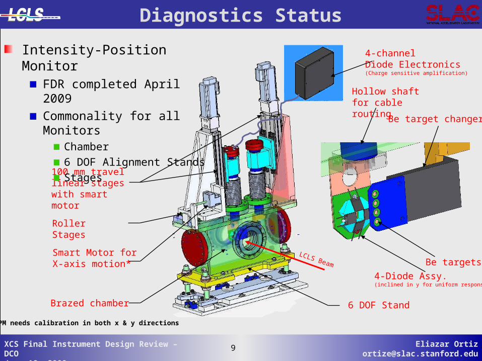
Diagnostics Status
100 mm travel linear stages with smart motor
6 DOF StandBrazed chamber
LCLS Beam
Intensity-Position MonitorFDR completed April 2009
Commonality for all MonitorsChamber
6 DOF Alignment Stands
Stages
4-channelDiode Electronics(Charge sensitive amplification)
Be target changer
4-Diode Assy.(inclined in y for uniform response)
Roller Stages
Smart Motor for X-axis motion* Be targets
Hollow shaft for cable routing
*IPM needs calibration in both x & y directions

10 Eliazar [email protected]
10XCS Final Instrument Design Review – DCOJune 18, 2009
Diagnostics Status
Intensity-Position Monitor Next StepsPlace orders for vendor items- Started April 09
Place order for fabricated components – June 09
Test First Articles- July 09
Update Models and Drawings based on First Article tests- August 09
Order production chamber assembliesDetail Design PM and PIM–Aug 09

11 Eliazar [email protected]
11XCS Final Instrument Design Review – DCOJune 18, 2009
Common Optics
Rigid Stand w/oDOF
Slits System UHV compatible
Low-z & high-z blades
Single/Double configurations
Double blades configuration(4 sets of blades)
Blade Form Factor
Single blades configuration(2 sets of blades)
Blades/blade mounts
Optical encoder
High-ZLow-Z
High-Z
Pink beam
Mono beam
12 Eliazar [email protected]
12XCS Final Instrument Design Review – DCOJune 18, 2009
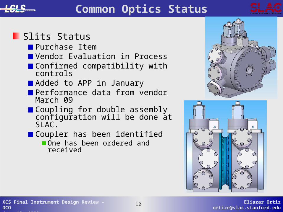
Common Optics Status
Slits StatusPurchase ItemVendor Evaluation in ProcessConfirmed compatibility with controlsAdded to APP in JanuaryPerformance data from vendor March 09Coupling for double assembly configuration will be done at SLAC.Coupler has been identified
One has been ordered and received

13 Eliazar [email protected]
13XCS Final Instrument Design Review – DCOJune 18, 2009
Common Optics Status
Slits Next StepsAward Contract June 09
Order Supports – June 09
Detail Assembly Drawings –June 09

14 Eliazar [email protected]
14XCS Final Instrument Design Review – DCOJune 18, 2009
Common Optics Status
Attenuator-Pulse Picker StatusCombined attenuator and pulse picker
Commercial pulse-picker packaged into same chamber
Final Design Review Completed
Chamber shared with Attenuator
Test ProgramBlade coating
PP performance with coated blade
Shared Design6 DOF Alignment Stands
Stage
Motorized actuatorsfor attenuator filters
6 DOF Stand
Optical CCDCamera
LCLS Beam
View port
Hollow shaft for cable routing
50 mm travel linear stage with smart motor
6” Rotating flanges
Lens
Si filters
Pulse-picker

15 Eliazar [email protected]
15XCS Final Instrument Design Review – DCOJune 18, 2009
Common Optics Status
Attenuator-Pulse PickerNext StepsFinalize Blade coating test –June 09
Order Supports Design – Feb 09
Place orders for vendor items- June 09Linear stage
Motors
Actuators
Place Order for fabricated Items- June 09Chamber
Stage support bracket
Mirror & Filter holders
Shaft Weldment

16 Eliazar [email protected]
16XCS Final Instrument Design Review – DCOJune 18, 2009
6 DOF Stand
LCLS Beam
Z-axis translation stage (±200mm)XPP only
Chamber similar to monitors
Actuator design similar to IPM
Lens Holder
Accommodates 3 different lens configurations
Quick lens stack removal
Common Optics StatusX-Ray Focusing Lenses Status
Commonality with MonitorsChamber
6 DOF Alignment Stands
Stages
Final Design Review- June 09

17 Eliazar [email protected]
17XCS Final Instrument Design Review – DCOJune 18, 2009
Common Optics StatusX-Ray Focusing Lenses Next Steps
Order lens holder parts for validation test- May 09
Issue award for lenses- July 09
Order other vendor Items- July 09Linear Stages
Motors
Be lenses

18 Eliazar [email protected]
18XCS Final Instrument Design Review – DCOJune 18, 2009
Common Optics Status
In-Vacuum Stages
Harmonic Rejection Mirrors StatusPDR performed on June 15
Design concept in workIn vacuum motion
Next StepsDetail Design June - Aug
Award Long Lead Procurements September 09
Mirrors
Stageschamber
Plane Si mirrors
BEAM DIRECTION

19 Eliazar [email protected]
19XCS Final Instrument Design Review – DCOJune 18, 2009
Cost
Engineering
Proc/Fab/Assy/Instl
Engineering $2,441,078
Proc/Fab/Assy/Instl $4,375,143
64%
36%

20 Eliazar [email protected]
20XCS Final Instrument Design Review – DCOJune 18, 2009
Cost & Schedule Performance – WBS 1.5

21 Eliazar [email protected]
21XCS Final Instrument Design Review – DCOJune 18, 2009
Project Critical Path
DCO has one design effort and multiple procurements to support the Instrument requirements.
The project is monitoring strings of activities with the least float
Items on the critical path are: XFLS Procurement Preps (14 day float, start May 2010)
HRM Procurement Preps (19 day float, start Oct 2010)
Activities to monitor from falling on the critical path:Check and Approve Dwgs PP (24 day float, start May 09)
PP procurement preps XPP (24 day float, start June 09)

22 Eliazar [email protected]
22XCS Final Instrument Design Review – DCOJune 18, 2009
Major Milestones
Activity Diff.Description Current Dates Accel. Dates (days) COMP: DCO Design Ready for XPP FIDR 02/17/09A 02/17/09A COMP: DCO Design Ready for CXI FIDR 02/27/09A 02/27/09A COMP: DCO Design Ready for XCS FIDR 7/6/09 7/6/09 0 COMP: Diagnostics & Common Optics XPP ES RFI 5/24/10 4/23/10 31 COMP: Diagnostics & Common Optics CXI ES RFI 9/13/10 8/19/10 25 COMP: Diagnostics & Common Optics CD-4 RFI 10/19/11 2/24/11 237
Early Finish

23 Eliazar [email protected]
23XCS Final Instrument Design Review – DCOJune 18, 2009
Procurement ScheduleDiff.
Activity ID Activity Description Early Start Activity Description Early Start (days)
9110522 Procurement - Pop-in Profile Monitor DI 01940 AWARD: PO - XPP PM Parts 7/8/2009 AWARD: PO - XPP PM Parts 9/10/09 -64DI 10640 AWARD: PO - CXI PM Parts 1/18/2010 AWARD: PO - CXI/XCS PM Parts 11/2/09 77DI 13320 AWARD: PO - XCS PM Parts 10/25/2010 11/2/09 3579110566 Procurement - Wavefront Monitor DI 13460 AWARD: PO - CXI Wavefront Monitor Parts 10/23/2009 AWARD: PO - CXI Wavefront Monitor Parts 10/1/09 229110526 Procurement - Pop-In Intensity Monitor DI 02600 AWARD: PO - XPP IO Mon 1st Article Parts 6/30/2009 AWARD: PO - XPP IO Mon 1st Article Parts 7/31/09 -31DI 10960 AWARD: PO - CXI IO Mon Parts 1/18/2010 AWARD: PO - CXI/XCS IO Mon Parts 11/2/09 77DI 13640 AWARD: PO - XCS IO Mon Parts 10/25/2010 11/2/09 3579110530 Procurement - Intensity-Position Monitor DI 03340 AWARD: PO - XPP IPM 1st Article Parts 6/29/2009 AWARD: PO - XPP IPM 1st Article Parts 7/31/09 -32DI 11280 AWARD: PO - CXI IPM Parts 1/18/2010 AWARD: PO - CXI/XCS IPM Parts 11/2/09 77DI 13960 AWARD: PO - XCS IPM Parts 10/4/2010 11/2/09 3369110534 Procurement - X-ray Focusing Lenses DI 09560 AWARD: PO - XPP XFL Long Lead Parts 8/17/2009 AWARD: PO - XPP XFL Long Lead Parts 8/19/09 -2DI 09640 AWARD: PO - XPP XFL Parts 10/4/2010 AWARD: PO - XPP XFL Other Parts 11/9/09 329DI 14200 AWARD: PO - XCS XFL Long Lead Parts 10/4/2010 AWARD: PO - XCS XFL Long Lead Parts 1/22/10 255DI 14280 AWARD: PO - XCS XFL Parts 11/15/2010 AWARD: PO - XCS XFL Other Parts 1/6/10 3139110538 Procurement - Primary Slits DI 41040 AWARD: PO - XPP Slits Long Lead Parts 5/18/2009 AWARD: PO - XPP/CXI/XCS Slits Long Lead Parts 5/18/2009 0DI 41075 AWARD: PO - XPP Slits Other Parts 9/14/2009 AWARD: PO - XPP/CXI/XCS Slits Other Parts 10/14/09 -30DI 41210 AWARD: PO - CXI Slits Long Lead Parts 1/18/2010 5/18/2009 245DI 41290 AWARD: PO - CXI Slits Other Parts 1/18/2010 10/14/09 96DI 42120 AWARD: PO - XCS Slits Other Parts 11/15/2010 10/14/09 397DI 42110 AWARD: PO - XCS Slits Long Lead Parts 1/5/2011 5/18/2009 597
9110546 Procurement - Attenuators / FiltersDI 12580 AWARD: PO - CXI Attenuator Parts 1/18/2010 AWARD: PO - XPP Attenuator Parts 9/8/09 132DI 10025 AWARD: PO - XPP Attenuator Parts 10/4/2010 AWARD: PO - CXI/XCS Attenuator Parts 11/2/09 336DI 14600 AWARD: PO - XCS Attenuator Parts 11/15/2010 11/2/09 3789110552 Procurement - Pulse Picker DI 12820 AWARD: PO - XPP Pulse Picker - Long Lead Parts 8/24/2009 AWARD: PO - XPP Pulse Picker - Long Lead Parts 9/29/09 -36DI 12900 AWARD: PO - XPP Pulse Picker - All Other Part 10/5/2009 AWARD: PO - XPP Pulse Picker - Other Parts 10/6/09 -1DI 13000 AWARD: PO - XPP Pulse Picker Parts w/Coating 11/16/2009 AWARD: PO - XPP Pulse Picker Parts w/Coating 11/10/09 6DI 14105 AWARD: PO - CXI Pulse Picker - Long Lead Parts 1/18/2010 AWARD: PO - CXI/XCS Pulse Picker - LL Parts 12/3/09 46DI 16025 AWARD: PO - CXI Pulse Picker - All Other Part 2/10/2010 AWARD: PO - CXI/XCS Pulse Picker Other Part 1/28/10 13DI 16065 AWARD: PO - CXI Pulse Picker Parts w/Coating 4/7/2010 AWARD: PO - CXI/XCS Pulse Picker Parts w/Coating 2/25/10 41DI 16005 AWARD: PO - XCS Pulse Picker - Long Lead Parts 10/4/2010 12/3/09 305DI 16045 AWARD: PO - XCS Pulse Picker - All Other Part 10/4/2010 1/28/10 249DI 16085 AWARD: PO - XCS Pulse Picker Parts w/Coating 10/4/2010 2/25/10 2219110562 Procurement - Harmonic Rejection Mirrors DI 10445 AWARD: PO - XPP HRM Long Lead Parts 11/15/2010 AWARD: PO - XPP HRM Long Lead Parts 9/17/09 424DI 14840 AWARD: PO - XCS HRM Long Lead Parts 11/15/2010 AWARD: PO - XPP HRM Other Parts 4/6/10 223DI 10465 AWARD: PO - XPP HRM Parts 1/12/2011 AWARD: PO - XCS HRM Long Lead Parts 11/2/09 436DI 14920 AWARD: PO - XCS HRM Parts 1/12/2011 AWARD: PO - XCS HRM Other Parts 4/6/10 281
Current Schedule Accelerated Schedule

24 Eliazar [email protected]
24XCS Final Instrument Design Review – DCOJune 18, 2009
Summary
Scope of DCO components for XPP, CXI, and XCS instruments has not changed significantly since CD-02The design of key diagnostics devices and optical components is mature and based on proven developments
at synchrotron sources worldwideby XTOD and LCLS e-beam groups
No major risks associated with the design or procurement of the DCO components
Bought components (slits) are “off the shelf” items Assembly components (CCD cameras, zoom lens, actuators, connectors) are commercially made with known performanceIn-house electronics design are based on proven technology and implementations
DCO overall cost and schedule performance is kept within margins.Critical Path is defined and monitoredAdvanced Procurements identifiedDCO is on track to support XCS schedule!


26 Eliazar [email protected]
26XCS Final Instrument Design Review – DCOJune 18, 2009
Overview
DCO will provide to all LUSI instrumentsCommon diagnostics for measuring FEL properties
Transverse beam profile
Incident beam intensity
Beam positions and pointing
Wavefield measurement at focus
Common Optical components for performing FEL manipulationsBeam size definition and clean-up
Attenuation
Pulse pattern selection and/or repetition rate reduction
Isolation of fundamental from high order harmonics
Focusing
Monochromatization*
*Engineering of mono is now managed by the XCS team

27 Eliazar [email protected]
27XCS Final Instrument Design Review – DCOJune 18, 2009
Global Physics Requirements
Physics requirements remained same as CD-2 and were based on characteristics of LCLS FEL
Ultra short pulses ~ 100 fs, and rep. rate of 120 Hz
Pulse energy 2 mJ, peak power ~ 20 GW, ave. power ~ .24 W
Fully coherent in transverse directions ~ expected to be predominantly TEM00
*
Exhibiting intrinsic intensity, temporal, spatial, timing fluctuations on per-pulse basis†, i.e.,
•Higher order Laguerre-Gaussian modes possible but negligible†FEL amplification process based on SASE from noise
LCLS Expected Fluctuations
Pulse intensity fluctuations~ 30 %(in contrast to synchrotron where fluctuation is Poisson limited)
Position & pointing jitter (x, y, , )
~ 10 % of beam diameter~ 10 % of beam divergence
Source point jitter (z)~ 5 m (leads to variations in apparent source size, or focal point location if focused)

28 Eliazar [email protected]
28XCS Final Instrument Design Review – DCOJune 18, 2009
Challenges Addressed
Scientific/technical challenges that were addressed
Sustaining the instantaneous LCLS X-ray FEL peak power Exercising careful material selection
Filters, scattering target, slits materials, focusing lens, beam stop etc.
Based on thermal calculations including melting threshold and onset of thermal fatigue & limited experimental data from FLASH
But no active cooling necessary
Providing coherent beam manipulationMinimizing wavefront distortion/coherence degradation
Filters, scattering target, slits, focusing lens
Reducing surface roughness and bulk non-uniformities
Minimizing diffraction effects i.e., utilizing cylindrical blades for slits
29 Eliazar [email protected]
29XCS Final Instrument Design Review – DCOJune 18, 2009
Challenges Addressed
Scientific/technical challenges that were addressedDetecting ultra-fast signals
Extracting electrical signals in ~ ns to minimize dark current contribution
i.e., charge-sensitive detection using diodes
Making per-pulse measurement if requiredEach pulse is different
Averaging over pulses may NOT be an option, requiring sufficiently high S/N ratio for each pulse
i.e., high-precision intensity measurements at < 0.1% based on single pulses, requiring larger raw signal than synchrotron cases

30 Eliazar [email protected]
30XCS Final Instrument Design Review – DCOJune 18, 2009
Pop-in Profile Monitor (WBS 1.5.2.1)
RequirementsDestructive; RetractableVariable FOV and resolution
At 50 m resolution, 12x12 mm2 FOVAt 4 m resolution, 1x1 mm2 FOV
Capable of per-pulse op. @ 120 Hz if requiredAttenuation used if necessary
YAG:Cescreen
45ºmirror
PurposesAid in alignment of X-ray optics
FEL is serial operation, automation enables maximum productivity
Characterization of X-ray beam spatial profile
FEL spatial mode structureEffects of optics on fully coherent FEL beam
Characterization of X-ray beam transverse spatial jitter
FEL beam exhibits intrinsic spatial fluctuations
ImplementationX-ray scintillation
50-75 m thin YAG:Ce single crystal scintillator
Optical imagingCapable ofdiffraction limited resolution if requiredNormal incidence geometry w/ 45º mirrorMotorized zoom lens120 Hz optical CCD camera
31 Eliazar [email protected]
31XCS Final Instrument Design Review – DCOJune 18, 2009
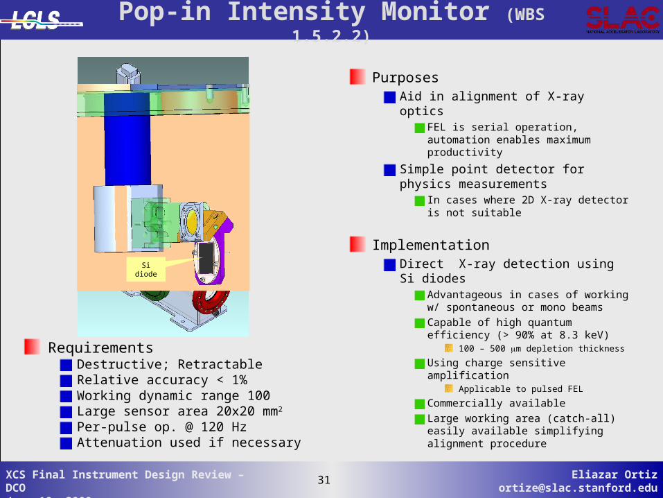
Pop-in Intensity Monitor (WBS 1.5.2.2)
RequirementsDestructive; RetractableRelative accuracy < 1%Working dynamic range 100Large sensor area 20x20 mm2
Per-pulse op. @ 120 HzAttenuation used if necessary
Sidiode
PurposesAid in alignment of X-ray optics
FEL is serial operation, automation enables maximum productivity
Simple point detector for physics measurements
In cases where 2D X-ray detector is not suitable
ImplementationDirect X-ray detection using Si diodes
Advantageous in cases of working w/ spontaneous or mono beams
Capable of high quantum efficiency (> 90% at 8.3 keV)
100 – 500 m depletion thickness
Using charge sensitive amplificationApplicable to pulsed FEL
Commercially available
Large working area (catch-all) easily available simplifying alignment procedure

32 Eliazar [email protected]
32XCS Final Instrument Design Review – DCOJune 18, 2009
Be thin foil
Array Si diodes
Intensity-Position Monitor (WBS 1.5.2.3)
RequirementsIn-situ, retractable if necessaryHighly transmissive (> 95%)Relative accuracy < 0.1%Working dynamic range 1000;Position accuracy in xy < 10 m;Per-pulse op. at 120 Hz;
PurposesAllow precise measurement of the intensity for normalization
Critical to experiments where signal from underlying physics is very small
Characterization of FEL fluctuationsPositional jitter ~ 10% of beam size Pointing jitter ~ 10% of beam divergenceSlitting beam down creates diffraction which may cause undesirable effects
ImplementationBased on back scattering from thin-foil
Detecting both Compton scattering & Thomson scattering Using Low-z (beryllium) for low attenuation especially at low X-ray energies
Using Si diode detectorsArray sensors for position measurementPointing measurement using 2 or more monitors

33 Eliazar [email protected]
33XCS Final Instrument Design Review – DCOJune 18, 2009
Wavefront Monitor (WBS 1.5.2.1)[in lieu of wavefront sensor]
Purposes
Wavefront characterization of focused X-ray beam at focal point
Wavefront measurement at focal point is not feasible by conventional methods due to damages
Providing supplemental scattering data in low Q w/ high resolution
Resolution obtained using X-ray direct detection is limited by detector technology, i.e., pixel sizes and per-pixel dynamic range
ImplementationX-ray scintillation
50-75 m thin YAG:Ce single crystal scintillator
Optical imagingCapable ofdiffraction limited resolution if required
Using computational algorithm for reconstruction of wavefield at focus
Iterative, post processing only if no large computer farm
RequirementsIn-situ; RetractableVariable FOV and resolution
At 50 m resolution,12x12 mm2 FOVAt 4 m resolution, 1x1 mm2 FOV
Per-pulse op. @ 120 HzAttenuation used if necessary
YAG:Cescreen
45ºmirror

34 Eliazar [email protected]
34XCS Final Instrument Design Review – DCOJune 18, 2009
X-ray Focusing Lenses (WBS 1.5.3.2)
PurposesIncrease the X-ray fluence at the sampleProduce small spot size in cases where slits do not work due to diffraction,
i.e., sample too far from slits
ImplementationBased on refractive lenses concept*
Concave shape due to X-ray refractive index 1-+i
Using Beryllium to minimize attenuationIn-line focus
Simpler than KB systems
no diff. orders as in Fresnel lens
ChromaticCon: re-positioning of focal point
Pro: Providing harmonic isolation if aperture used
Some attenuation at very low X-ray energies ~ 2 keV
RequirementsProduce variable spot size
For XPP instrument 2-10 m in focus40-60 m out-of-focus
Minimize wavefront distortion and coherence degradationWithstand FEL full flux *B. Lengeler, et al, J. Synchrotron Rad. (1999). 6, 1153-1167
Be Lensstack
Be lenses

35 Eliazar [email protected]
35XCS Final Instrument Design Review – DCOJune 18, 2009
RequirementsRepeatability in x&y < 2 m0 – 10 mm gap setting10-9 in transmission from 2-8.3keV10-8 in transmission at 25 keVMinimize diffraction/wavefront distortionWithstand FEL full flux
Slits System (WBS 1.5.3.3)
Purposesdefine beam transverse sizes
Pink and mono beam
Clean up scatterings (halo) around beam perimeter
ImplementationBased on cylindrical blades concept*
Minimize scattering from edges and external total reflections
Offset in Z to allow fully closing
Using single or double configurations for pink or mono beam applications
Single configurationBlade material: Si3N4 to stop low energies
Or blade material: Ta/W alloy to stop low fluence low or high energies
Double configuration1st blades: Si3N4, 2nd blades: Ta/W alloy to stop low and high energies
*D. Le Bolloc’h, et al, J. Synchrotron Rad. (2002). 9, 258-265
High-ZLow-Z
High-Z
Pink beam
Mono beamD=3 mm
36 Eliazar [email protected]
36XCS Final Instrument Design Review – DCOJune 18, 2009
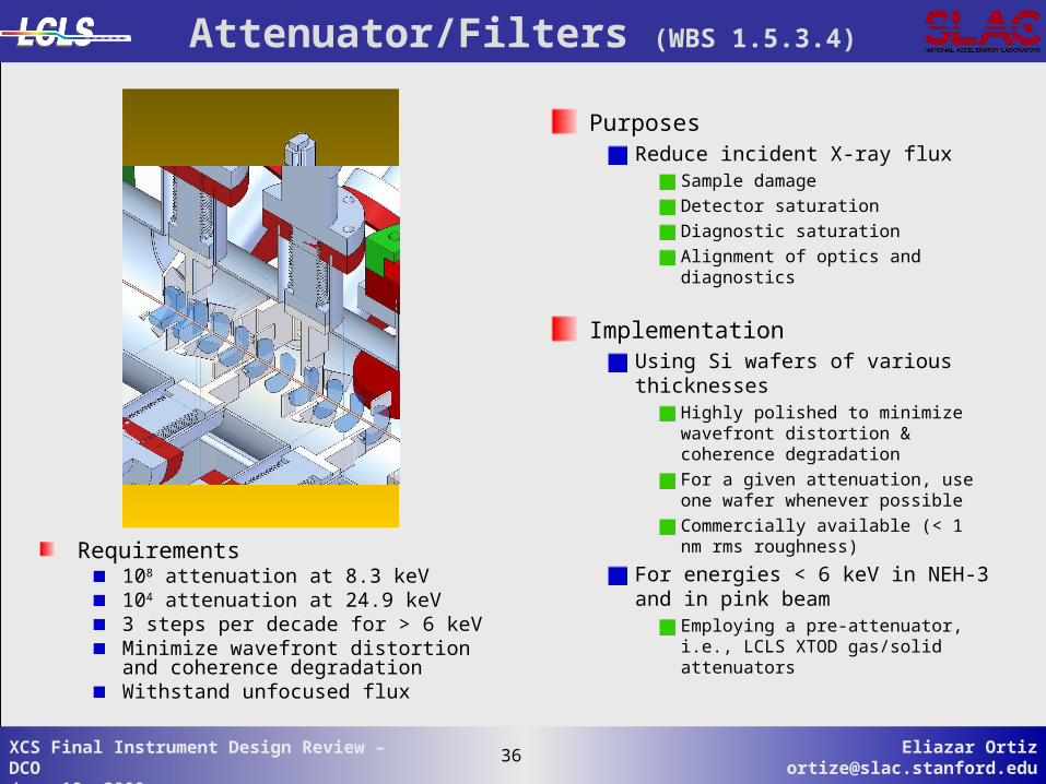
Attenuator/Filters (WBS 1.5.3.4)
PurposesReduce incident X-ray flux
Sample damage
Detector saturation
Diagnostic saturation
Alignment of optics and diagnostics
ImplementationUsing Si wafers of various thicknesses
Highly polished to minimize wavefront distortion & coherence degradation
For a given attenuation, use one wafer whenever possible
Commercially available (< 1 nm rms roughness)
For energies < 6 keV in NEH-3 and in pink beam
Employing a pre-attenuator, i.e., LCLS XTOD gas/solid attenuators
Requirements108 attenuation at 8.3 keV104 attenuation at 24.9 keV3 steps per decade for > 6 keVMinimize wavefront distortion and coherence degradationWithstand unfocused flux

37 Eliazar [email protected]
37XCS Final Instrument Design Review – DCOJune 18, 2009
Pulse Picker (WBS 1.5.3.5)
*http://www.azsol.ch/
PurposesSelect a single pulse or any sequence of pulses
Reduce LCLS repetition rateImportant if longer sample recover time is needed
Damage experiments - sample needs to be translated
ImplementationBased on a commercial mechanical teeter-totter*
Steel blade fully stops beam
Capable of ms transient time
Simple to operateUse TTL pulses
Requires 100 m Si3N4 to protect the steel bladeRequirements
< 3 ms switching time
< 8 ms in close/open cycle time
Only for < 10 Hz operation
Withstand full LCLS flux

38 Eliazar [email protected]
38XCS Final Instrument Design Review – DCOJune 18, 2009
A
B
C
Harmonic Rejection Mirrors (WBS 1.5.3.6)
PurposesProvide isolation of FEL fundamental from high harmonics
LUSI detectors not designed to be energy resolved
ImplementationLow pass filter using X-ray mirrors at grazing incidence
Using highly polished Si single crystal substrates
3.5 mrad incidence angle
300 mm long
No pre-figure, no bender
Figure-error specs defined to ensure FEL natural divergence not effected
R ~ 150 km
Roughness specs to minimize wavefront distortion and coherence degradation
rms ~ 0.1 nm
RequirementsEnergy range: 6-8.265 keV
104 contrast ratio between fundamental and the 3rd harmonic
80% overall throughput for fundamental
Minimize wavefront distortion
Withstand full FEL flux
39 Eliazar [email protected]
39XCS Final Instrument Design Review – DCOJune 18, 2009
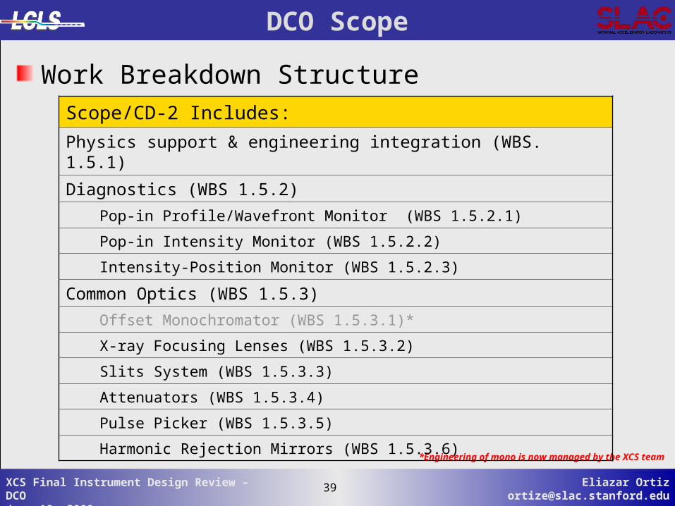
*Engineering of mono is now managed by the XCS team
DCO Scope
Work Breakdown StructureScope/CD-2 Includes:
Physics support & engineering integration (WBS. 1.5.1)
Diagnostics (WBS 1.5.2)
Pop-in Profile/Wavefront Monitor (WBS 1.5.2.1)
Pop-in Intensity Monitor (WBS 1.5.2.2)
Intensity-Position Monitor (WBS 1.5.2.3)
Common Optics (WBS 1.5.3)
Offset Monochromator (WBS 1.5.3.1)*
X-ray Focusing Lenses (WBS 1.5.3.2)
Slits System (WBS 1.5.3.3)
Attenuators (WBS 1.5.3.4)
Pulse Picker (WBS 1.5.3.5)
Harmonic Rejection Mirrors (WBS 1.5.3.6)