1 definition of capacitance c o = capacitance of a parallel plate capacitor in free space q o =...
TRANSCRIPT

1
Definition of Capacitance
Co = capacitance of a parallel plate capacitor in free spaceQo = charge on the platesV = voltageo = absolute permittivity (8.854 pF/m or pC/(V. m)A = area of a plated = distance of the space between the plates
Farad) (unit d
A
V
QC oo
o
+Qo -Qo
V
d A
+ -+ -
+ -

2
Definition of Charge density
density charge is D
)C/m (unit 2
d
VD
A
Q
d
V
A
Qd
A
V
Qd
A
V
QC
oo
ooo
oo
ooo
+Qo -Qo
V
d A
+ -+ -
+ -
3
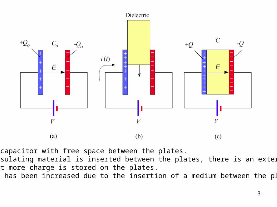
(a) Parallel plate capacitor with free space between the plates.(b) As a slab of insulating material is inserted between the plates, there is an external current flow indicating that more charge is stored on the plates.(c) The capacitance has been increased due to the insertion of a medium between the plates.

4
Definition of Relative Permittivity or Dielectric constant
r = relative permittivity or dielectric constant, Q = charge on the plates with a dielectric medium, Qo = charge on the plates with free space between the plates, C = capacitance with a dielectric medium, Co =
capacitance of a parallel plate capacitor in free space
d
AC
C
C
Q
Q or
oo
r
D
D
o

5
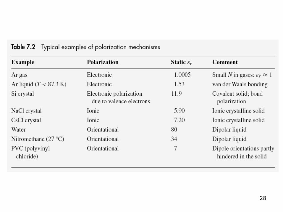
Dielectric constant is a material property that is frequency dependent.For a dielectric, the voltage, at which an appreciable current flow (or breakdown) occurs, is called “dielectric strength”.
Material r or k (measure at 1 kHz)
Dielectric strength (kV/mm)
Al2O3 (99.9%) 10.1 9.1
Al2O3 (99.5%) 9.8 9.5
BeO (99.5%) 6.5 10.2

6
The definition of electric dipole moment.
Definition of Dipole Moment
p = electric dipole moment, Q = charge, a = vector from the negative to the positive charge
p = Qa

7
Three major polarization mechanisms
1. Electronic polarization
2. Ionic polarization
3. Orientation (dipolar) polarization

8
The origin of electronic polarization.

9
Definition of Polarizability
pinduced = induced dipole moment, = polarizability, E = electric field
pinduced = E
Electronic Polarization
pe = magnitude of the induced electronic dipole moment, Z = number of electrons orbiting the nucleus of the atom, x = distance between the nucleus and the center of negative charge, = constant, E =
electric field
E
β
eZxZep
22
e )(

10
Static Electronic Polarizability
e = electronic polarizability
Z = total number of electrons around the nucleus
me = mass of the electron in free space (9.1094x10⁻³¹ kg)
o = natural oscillation frequency (= 2fo)
e = electron charge (1.60218x10⁻¹⁹ C)
e Ze2
me o2

11

12
e Ze2
me o2
2/1
eo Zm
Electronic polarizability and its resonance frequency versus the number of electrons in theatom (Z). The dashed line is the best-fit line.

13
(a) When a dilectric is placed in an electric field, bound polarization charges appear on the opposite surfaces.
(b) The origin of these polarization charges is the polarization of the molecules of the medium.
(c) We can represent the whole dielectric in terms of its surface polarization charges +QP and -QP.

14
Definition of Polarization Vector
P = Polarization vector, p1, p2, ..., pN are the dipole moments induced at N molecules in the volume
P = 1
Volume [p1 + p2 +... + pN ]
Definition of Polarization Vector
pav = the average dipole moment per molecule
P = polarization vector, N = number of molecules per unit volume
P = Npav
15
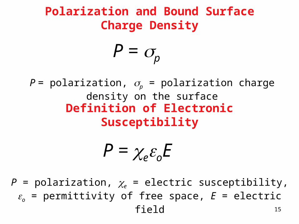
Polarization and Bound Surface Charge Density
P = polarization, p = polarization charge density on the surface
P = p
Definition of Electronic Susceptibility
P = polarization, e = electric susceptibility, o = permittivity of free space, E = electric field
P = eoE

16
Polarization charge density on the surface of a polarized medium is related to the normalcomponent of the polarization vector.

17
Electric Susceptibility and Polarization
e = electric susceptibility, o = permittivity of free space, N = number of molecules per unit volume, e = electronic polarizability
e 1
o
N e
Relative Permittivity and Electronic Susceptibility
r = relative permittivity, e = electric susceptibility
r = 1 + e

18
Relative Permittivity and Polarizability
r = relative permittivity
N = number of molecules per unit volume
e = electronic polarizability
o = permittivity of free space
Assumption: Only electronic polarization is present
r 1N e
o

19
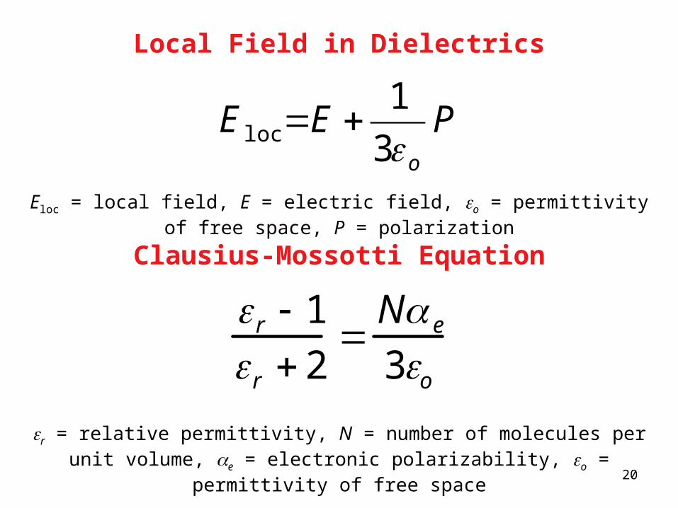
The electric field inside a polarized dielectric at the atomic scale is not uniform. The local field is the actual field that acts on a molecules. It can be calculated by removing that molecules and evaluating the field at that point from the charges on the plates and the dipoles surrounding the point.
20
Local Field in Dielectrics
Eloc = local field, E = electric field, o = permittivity of free space, P = polarization
Po3
1loc EE
Clausius-Mossotti Equation
r = relative permittivity, N = number of molecules per unit volume, e = electronic polarizability, o = permittivity of free space
r 1
r 2
N e
3o

21
Example 1
The electronic polarization polarizability of the Ar atom is 1.7x10-40 Fm-2 . What is the static dielectric constant, r, of solid Ar (below 84 K) if its density is 1.8 g/cm3 and atomic mass = 39.95 g/mol, NA = 6.02x10²³ atom/mol

22
(a) Valence electrons in covalent bonds in the absence of an applied field.
(b) When an electric field is applied to a covalent solid, the valence electrons in the covalent bonds are shifted very easily with respect to the positive ionic cores. The whole solid becomes polarized due to the collective shift in the negative charge distribution of the valence electrons.
(Supplements)

23
Example 2
Consider a pure Si crystal that has r = 11.9. if its density is 2.33 g/cm3 and atomic mass = 28.09 g/mol, NA = 6.02x10²³ atom/mol.
a. What is the electronic polarization due to valence electrons per Si atom (if one could portion the observed crystal polarization to individual atom).
b. If a Si crystal sample is electroded opposite faces and has voltage applied across it. By how much is the local field greater than the applied field?
c. What is the resonant frequency fo corresponding to o.

24
(a) A NaCl chain in the NaCl crystal without an applied field. Average or net dipole moment per ion is zero.
(b) In the presence of an applied field the ions become slightly displaced which leads to a net average dipole moment per ion.

25
(a) A HCl molecule possesses a permanent dipole moment p0.(b) In the absence of a field, thermal agitation of the molecules results in zero net averagedipole moment per molecule.(c) A dipole such as HCl placed in a field experiences a torque that tries to rotate it to align p0
with the field E.(d) In the presence of an applied field, the dipoles try to rotate to align with the field against thermal agitation. There is now a net average dipole moment per molecule along the field.
Orientation (dipolar) polarization

26
Average Dipole Moment in Orientational Polarization
pav = average dipole moment, po = permanent dipole moment, E = electric field, k = Boltzmann constant, T = temperature
kT
pp o E
2
av 3
1
Dipolar Orientational Polarizability
d = dipolar orientational polarizability, po = permanent dipole moment
d 1
3
po2
kT
27
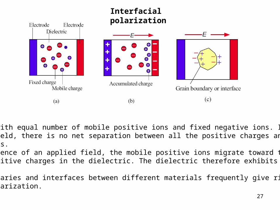
(a) A crystal with equal number of mobile positive ions and fixed negative ions. In the absence of a field, there is no net separation between all the positive charges and all the negative charges.(b) In the presence of an applied field, the mobile positive ions migrate toward the negativecharges and positive charges in the dielectric. The dielectric therefore exhibits interfacialpolarization.(c) Grain boundaries and interfaces between different materials frequently give rise to Interfacial polarization.
Interfacial polarization
28

29
Total Induced Dipole Moment
pav = e Eloc + i Eloc + d Eloc
pav = average dipole moment, Eloc = local electric field, e = electronic polarizability, i = ionic polarizability, d = dipolar (orientational) polarizability
Clausius-Mossotti Equation
r = dielectric constant, o = permittivity of free space, Ne = number of atoms or ions per unit volume, e = electronic polarizability, Ni = number of ion pairs per
unit volume , i = ionic polarizability
)(3
1
2
1iiee
or
r NN

30
Example 3
Consider the CsCl crystal which has one Cs+-Cl- pair per unit cell and a lattice parameter a of 0.412 nm. The electronic polarization of Cs+ and Cl- ions is 3.35x10-40 F m2, 3.40x10-40 respectively, and the mean ionic polarizibility per ion pair is 6x10-40 F m2. What is the dielectric constant at low frequencies and that at optical frequency?

31
The dc field is suddenly changed from Eo to E at time t = 0. The induced dipole moment p has to decrease from d(0)Eo to a final value of ad(0)E. The decrease is achieved by random collisions of molecules in the gas.
Relaxation process

32
Dipolar Relaxation Equation
p = dipole moment, dp/dt = rate at which the induced dipole moment is changing, d = dipolar orientational polarizability, E = electric field, = relaxation time
)exp( ;)0(
tjEEp
dt
dpo
d
E
d () = dipolar orientational polarizability as a function of , = angular frquency of the applied field, = relaxation time, j is (1).
Orientational Polarizability and Frequency (under ac field)
j
tjEp
dd
od
1
)0()(
)exp()(

33
(a) An ac field is applied to a dipolar medium. The polarization P(P = Np) is out of phase withthe ac field. (b) The relative permittivity is a complex number with real (r') and imaginary (r'') parts that exhibit frequency dependence.

34
Complex Relative Permittivity
r = dielectric constant
r = real part of the complex dielectric constant
r = imaginary part of the complex dielectric constant
j = imaginary constant (1)
r r j r

35
The dielectric medium behaves like an ideal (lossless) capacitor of capacitance C which is in parallel with a conductance Gp.

36
Admittance of a Parallel Plate Capacitor
Y = admittance, = angular frequency of the applied field , C = capacitance, GP = conductance
Y = jC + GP
Loss Tangent
tan = loss tangent or loss factor, r = real part of the complex dielectric constant, r = imaginary part of the complex dielectric constant
tan rr

37
Dielectric Loss per Unit Volume
Wvol = dielectric loss per unit volume, = angular frquency of the applied field , E = electric field, o = permittivity of free
space, r = real part of the complex dielectric constant, tan = loss tangent or loss factor
tan = 2vol roW E

38
The frequency dependence of the real and imaginary parts of the dielectric constant in the presence of interfacial, orientational, ionic, and, electronic polarization mechanisms.

39
(a) Real and imaginary part is of the dielectric constant, r' and r'' versus frequency for (a) a polymer, PET, at 115 C and (b) an ionic crystal, KCl, at room temperature. both exhibit relaxation peaks but for different reasons.SOURCE: Data for (a) from author’s own experiments using a dielectric analyzer (DEA), (b) from C. Smart, G.R. Wilkinson, A. M. Karo, and J.R. Hardy, International Conference onlattice Dynamics, Copenhagen, 1963, as quoted by D. G. Martin, “The Study of the Vibrationof Crystal Lattices by Far Infra-Red Spectroscopy,” Advances in Physics, 14, no. 53-56, 1965,pp. 39-100.

40

41
Field E2 in a small cavity (e.g. air) is higher than the field in the solid since r1 > r2
Field in the cavity is higher than the field in the solid

42
A thin slab of dielectric is placed in the middle of a parallel plate capacitor. The field inside the thin slab is E2

43
44
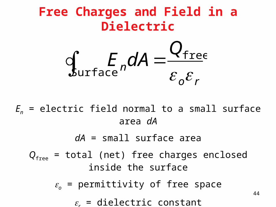
Free Charges and Field in a Dielectric
En = electric field normal to a small surface area dA
dA = small surface area
Qfree = total (net) free charges enclosed inside the surface
o = permittivity of free space
r = dielectric constant
ron
QdA
free
Surface E

45
Corona and Partial Discharges: (a) The field is greatest on the surface of the cylindrical conductor facing ground. If the voltage is sufficiently large this field gives rise to a corona discharge. (b) The field in a void within a solid can easily cause partial discharge. (c) The field in the crack at the solid-metal interface can also lead to a partial discharge.

46
An exaggerated schematic illustration of a soft dielectric medium experiencing strong compressive forces to the applied voltage.

47
(a) A schematic illustration of electrical treeing breakdown in a high voltage coaxial cable which was initiated by a partial discharge in the void at the inner conductor - dielectric interface.
(b) A schematic diagram of a typical high voltage coaxial cable with semiconducting polymer layers around the inner conductor and around the outer surface of the dielectric.

48

49
Some typical water trees found in field aged cables. (Left: Trees in a cable with tape and graphite insulation. Right: Trees in a cable with strippable insulation.)SOURCE: P. Werellius, P. Tharning, R. Eriksson,B . Holmgren. J. Gafvert, “Dielectric Spectroscopy for Diagnosis of Water Tree Deterioration in XLPE Cables” IEEE Transactions on Dielectrics and Electrical Insulation, Vol. 8, February 2001, p 34, Figure 10 ( IEEE, 2001)

50
Coaxial cable connector with traces of corona discharge; electrical treeing.SOURCE: M. Mayer and G.H. Schröder , “Coaxial 30 kV Connectors for the RG220/U Cable: 20 Years of Operational Experience”IEEE Electrical Insulation Magazine , Vol. 16, March/April 2000, p 11, Figure 6. ( IEEE, 2000)

51
Tree and bush type electrical discharge structures (a) Voltage, V = 160 kV, gap spacing d = 0.06 m at various times. (b) Dense bush discharge structure, V = 300 kV, d = 0.06 m at various times.SOURCE: V. Lopatin, M.D. Noskov, R. Badent, K. Kist, A.J. Swab, “Positive Discharge Development in Insulating Oil: Optical Observation and Simulation” IEEE Trans. on Dielec and Elec. Insulation Vol. 5, No. 2, 1998, p. 251, Figure 2.( IEEE, 1998)

52
Time to breakdown and the field at breakdown, Ebr, are interrelated and depend on the mechanism that causes the insulation breakdown. External discharges have been excluded (based on L.A. Dissado and J.C. Fothergill, Electrical Degradation and Breakdown in Polymers, Peter Peregrinus Ltd. for IEE, UK, © 1992, p. 63)

53
Examples of dielectrics that can be used for various capacitance values.

54
Examples of dielectrics that can be used in various frequency ranges.

55
Sindle0 and multilayer dielectric capacitors.

56
Two polymer tapes in (a), each with a metallized film electrode on the surface (offset from Other), can be rolled together (like a Swiss roll) to obtain a polymer film capacitor as in (b).As the two separate metal films are lined at opposite edges, electroding is done over the wholeside surface.

57
Aluminum electrolytic capacitor.

58
Solid electrolyte tantalum capacitor.(a) A cross section without fine detail.(b) An enlarged section through the Ta capacitor.

59
Comparison of dielectrics for capacitor applications
Capacitor name Polypropylene Polyester Mica Aluminum, electrolytic
Tantalum, electrolytic, solid
High-K ceramic
Dielectric Polymer film Polymer film Mica Anodized Al2O3
film
Anodized Ta2O5
film
X7R BaTiO3 base
r 2.2 – 2.3 3.2 – 3.3 6.9 8.5 27 2000
tan 4 10-4 4 10-3 2 10-4 0.05 - 0.1 0.01 0.01
Ebr (kV mm-1) DC 100 - 350 100 - 300 50 - 300 400 - 1000 300 - 600 10
d (typical minimum) 3 - 4 µm 1 µm 2 - 3 µm 0.1 µm 0.1 m 10 µm
Cvol (µF cm-3) 2 30 15 7,500a 24,000a 180
Rp = 1/Gp; C = 1 F;
1000 Hz
400 k 40 k 800 k 1.5 - 3 k 16 k 16 k
Evol (mJ cm-3)b 10 15 8 1000 1200 100
Polarization Electronic Electronic and Dipolar
Ionic Ionic Ionic Large ionic displacement
NOTES: Typical values. h = 3 assumed. The table is for comparison purposes only. Breakdown fields are typical DC values, and can vary substantially, by at least an order of magnitude; Ebr depends on the thickness, material quality and the duration of the applied voltage. a Proper volumetric calculations must also consider the volumes of electrodes and the electrolyte necessary for these dielectrics to work; hence the number would have to be decreased. b Evol depends very sensitively on Ebr and the choice of h; hence it can vary substantially. Polyester is PET, or polyehthylene terephthalate. Mica is potassium aluminosilicate, a muscovite crystal. X7R is the name of a particular BaTiO3-based ceramic solid solution.
60
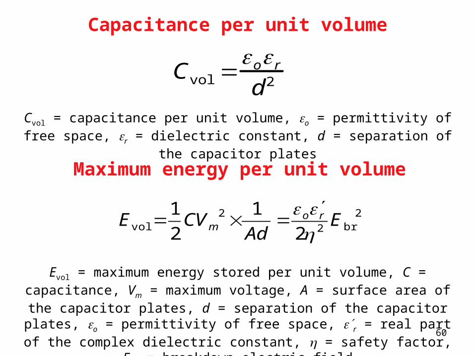
Capacitance per unit volume
Cvol = capacitance per unit volume, o = permittivity of free space, r = dielectric constant, d = separation of the capacitor plates
Cvol or
d2
Maximum energy per unit volume
Evol = maximum energy stored per unit volume, C = capacitance, Vm = maximum voltage, A = surface area of the capacitor plates, d = separation of the capacitor plates, o = permittivity of free space, r = real part of the complex dielectric
constant, = safety factor, Ebr = breakdown electric field
2br2
2vol 2
1
2
1E
ro
m AdCVE

61
Dielectric loss per unit volume
Wvol = dielectric loss per unit volume, Ebr = breakdown electric field, = safety factor,o = permittivity of free space, r = real part of the complex dielectric constant,
tan = loss tangent or loss factor, = angular frequency of the applied field
tan2
2br
vol roW E

62
(a) A polymer dielectric that has dipolar side groups attached to the polymer chains. With no applied field, the dipoles are randomly oriented.(b) In the presence of an applied field, some very limited rotation enables dipolar polarizationto take place.(c) Near the softening temperature of the polymer, the molecular motions are rapid and thereis also sufficient volume between chains for the dipoles to align with the field. The dipolarcontribution to r is substantial, even at high frequencies.

63
Real part of the dielectric constant, r', and loss tangent, tan, at 1 kHz vs. temperature from Dielectric Analysis, DEA [by Kasap and Maeda (1995)]