1 , chiara bedon 2,* , adesh singh 1, ashish premkishor khatri
TRANSCRIPT

buildings
Review
An Abridged Review of Buckling Analysis of CompressionMembers in Construction
Manmohan Dass Goel 1 , Chiara Bedon 2,* , Adesh Singh 1, Ashish Premkishor Khatri 1
and Laxmikant Madanmanohar Gupta 1
�����������������
Citation: Goel, M.D.; Bedon, C.;
Singh, A.; Khatri, A.P.; Gupta, L.M.
An Abridged Review of Buckling
Analysis of Compression Members in
Construction. Buildings 2021, 11, 211.
https://doi.org/10.3390/
buildings11050211
Academic Editor: Francisco
López Almansa
Received: 12 March 2021
Accepted: 14 May 2021
Published: 18 May 2021
Publisher’s Note: MDPI stays neutral
with regard to jurisdictional claims in
published maps and institutional affil-
iations.
Copyright: © 2021 by the authors.
Licensee MDPI, Basel, Switzerland.
This article is an open access article
distributed under the terms and
conditions of the Creative Commons
Attribution (CC BY) license (https://
creativecommons.org/licenses/by/
4.0/).
1 Department of Applied Mechanics, Visvesvaraya National Institute of Technology, Nagpur 440 010, India;[email protected] (M.D.G.); [email protected] (A.S.); [email protected] (A.P.K.);[email protected] (L.M.G.)
2 Department of Engineering and Architecture, University of Trieste, 34127 Trieste, Italy* Correspondence: [email protected]; Tel.: +39-040-5583837
Abstract: The column buckling problem was first investigated by Leonhard Euler in 1757. Since then,numerous efforts have been made to enhance the buckling capacity of slender columns, because oftheir importance in structural, mechanical, aeronautical, biomedical, and several other engineeringfields. Buckling analysis has become a critical aspect, especially in the safety engineering design since,at the time of failure, the actual stress at the point of failure is significantly lower than the materialcapability to withstand the imposed loads. With the recent advancement in materials and composites,the load-carrying capacity of columns has been remarkably increased, without any significant increasein their size, thus resulting in even more slender compressive members that can be susceptible tobuckling collapse. Thus, nonuniformity in columns can be achieved in two ways—either by varyingthe material properties or by varying the cross section (i.e., shape and size). Both these methodsare preferred because they actually inherited the advantage of the reduction in the dead load of thecolumn. Hence, an attempt is made herein to present an abridged review on the buckling analysis ofthe columns with major emphasis on the buckling of nonuniform and functionally graded columns.Moreover, the paper provides a concise discussion on references that could be helpful for researchersand designers to understand and address the relevant buckling parameters.
Keywords: buckling; compression members; Euler’s load; nonprismatic sections; imperfections;slenderness
1. Introduction
Compression members are an integral part of the structures, and unlike other load-bearing members, their capacity to carry loads is governed by the different sets of influ-encing parameters. This difference in behaviour questions their structural integrity andnecessitates the analysis of compression members with numerical models that could offer aminimum deviation from the reality and thus ensure a fairly close estimation of the actualbuckling load.
While the stability issue was first pointed out in 1675 by Hooke [1], several otherformulations followed especially during the 18th century, and even further important de-velopments in the support of design have been obtained in the last few decades. Currently,the development of novel design applications, materials, and composites solutions enforcesa further need for dedicated calculation tools. In the last decades, the column bucklingissue has become relevant for traditional constructional applications but especially forinnovative material solutions, as in Figure 1, in which selected examples can be seen forFRP-reinforced concrete columns [2], repaired timber columns [3] and even hollow squareglass columns [4].
Buildings 2021, 11, 211. https://doi.org/10.3390/buildings11050211 https://www.mdpi.com/journal/buildings

Buildings 2021, 11, 211 2 of 17
Buildings 2021, 11, 211 2 of 17
of short columns, while slender columns are discussed in Section 4. Finally, Section 4.5 presents a subdiscussion on compressed members with variable stiffness due to thermal gradients and constructional materials that can be remarkably sensitive to degradation and hence to the premature column buckling collapse. It is important to mention that this work is primarily focused on the global buckling of the compression member.
(a) (b) (c)
Figure 1. Examples of column buckling for constructional members: (a) FRP-reinforced concrete columns (reproduced from [2] with permission from Elsevier, license n. 5026030791841); (b) re-paired timber columns (reproduced from [3] with permission from Elsevier, license n. 5026030922470); and (c) hollow square glass columns (reproduced from [4] with permission from Elsevier, license n. 5026031011542).
2. Basics The necessary preliminary analysis of the stability problem was proposed by Hooke
in 1675, wherein it was shown that the displacement in any structural body is directly proportional to the load causing the displacement. This law can be applied to spring bod-ies, stone, wood, metal, etc., and it is commonly known as Hooke’s law [1]. Further, Ber-noulli studied the curvature and deflection of a cantilever beam using Hooke’s law in 1705. It was Euler who was credited with the first systematic study of the stability problem in equilibrium. In his first publications, Euler investigated the stability of a hinged bar, having flexural rigidity (EI), in equilibrium, subjected to an axially compressive force (p) and uniformly distributed load (q) along the longitudinal axis (z) by two different ap-proaches [5–8]. It is interesting to note that Euler has defined all his formulations in terms of Ek2 instead of EI, with E defined as strength property and k2 as a dimensional property of the column. Further, the transformation from Ek2 to EI requires the knowledge of Hooke’s law, and it was Coulomb, who, for the first time, applied Hooke’s law and equa-tion of static equilibrium to develop the bending moment and normal stress due to the elastic bending in cantilever column as follows [9]: 𝐸𝐼 𝑑 𝑣𝑑𝑧 + 𝑞𝑧 𝑑𝑣𝑑𝑧 + 𝑝 𝑑𝑣𝑑𝑧 = 0 (1)
As is evident from Equation (1), its solution will contain only three constants, and the equation has failed to satisfy four boundary conditions. Euler identified this error and presented a corrected differential equation in his third paper by including the presence of a horizontal force N [5]. However, it is interesting to note that Euler did a numerical mis-take, and calculated the second eigenvalue instead of the first, which was later corrected
Figure 1. Examples of column buckling for constructional members: (a) FRP-reinforced concretecolumns (reproduced from [2] with permission from Elsevier®, license n. 5026030791841); (b) repairedtimber columns (reproduced from [3] with permission from Elsevier®, license n. 5026030922470);and (c) hollow square glass columns (reproduced from [4] with permission from Elsevier®, license n.5026031011542).
In Section 2, some basics concepts and background theories are first presented.Section 3 provides a brief overview of the methods and critical issues on the buckling fail-ure of short columns, while slender columns are discussed in Section 4. Finally, Section 4.5presents a subdiscussion on compressed members with variable stiffness due to thermalgradients and constructional materials that can be remarkably sensitive to degradation andhence to the premature column buckling collapse. It is important to mention that this workis primarily focused on the global buckling of the compression member.
2. Basics
The necessary preliminary analysis of the stability problem was proposed by Hookein 1675, wherein it was shown that the displacement in any structural body is directlyproportional to the load causing the displacement. This law can be applied to springbodies, stone, wood, metal, etc., and it is commonly known as Hooke’s law [1]. Further,Bernoulli studied the curvature and deflection of a cantilever beam using Hooke’s lawin 1705. It was Euler who was credited with the first systematic study of the stabilityproblem in equilibrium. In his first publications, Euler investigated the stability of a hingedbar, having flexural rigidity (EI), in equilibrium, subjected to an axially compressive force(p) and uniformly distributed load (q) along the longitudinal axis (z) by two differentapproaches [5–8]. It is interesting to note that Euler has defined all his formulations interms of Ek2 instead of EI, with E defined as strength property and k2 as a dimensionalproperty of the column. Further, the transformation from Ek2 to EI requires the knowledgeof Hooke’s law, and it was Coulomb, who, for the first time, applied Hooke’s law andequation of static equilibrium to develop the bending moment and normal stress due tothe elastic bending in cantilever column as follows [9]:
EId3vdz3 + qz
dvdz
+ pdvdz
= 0 (1)
As is evident from Equation (1), its solution will contain only three constants, andthe equation has failed to satisfy four boundary conditions. Euler identified this error andpresented a corrected differential equation in his third paper by including the presence
Buildings 2021, 11, 211 3 of 17
of a horizontal force N [5]. However, it is interesting to note that Euler did a numericalmistake, and calculated the second eigenvalue instead of the first, which was later correctedby [10–12]. Thus, the equation of static equilibrium (Equation (2)) to develop bendingmoment and normal stress due to the elastic bending in a cantilever column is:
EId3vdz3 + qz
dvdz
+ pdvdz
= N (2)
Euler’s analytical conclusion supported the experimental results obtained by Muss-chenbroek [13] for slender wooden columns. However, Coulomb discarded the result ofMusschenbroek and concluded that the breaking strength was independent of length, basedon experiments on masonry columns [9]. Duleau, Hodgkinson, Considère, and Engesserdiscussed Euler’s formulation and its exclusive validity for “slender” columns [13–17].Moreover, Hodgkinson proposed an empirical formula for the design of short columnsbased on the experimental investigations on cast-iron columns. In the year 1845, Lamarleproposed a critical load expression in terms of the critical stress and stated that Eulerformulation is applicable when the critical stress (σcr) is less than the elastic limit (σ0) forthe constructional material in use. In other words, it is applicable for the struts whoseslenderness ratio (l/h) is greater than the limit value given as follows i.e., Equation (3) [18]:(
lr
)2=
π2Eσ0
(3)
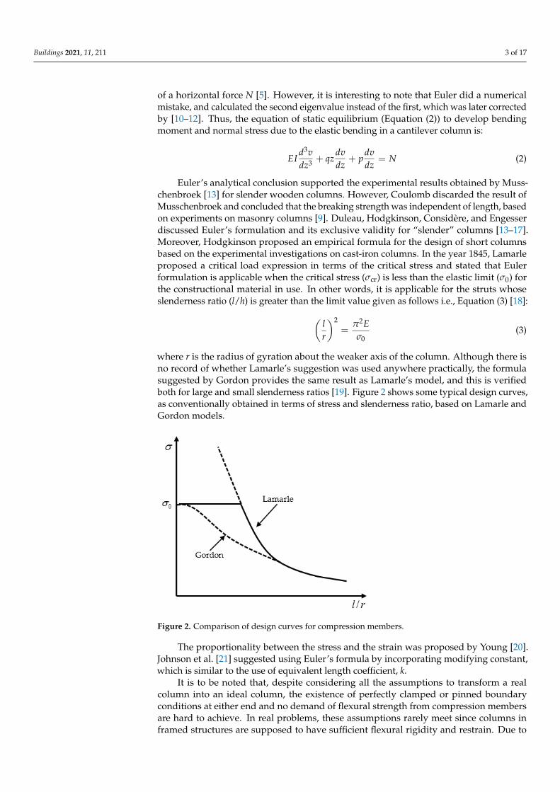
where r is the radius of gyration about the weaker axis of the column. Although there isno record of whether Lamarle’s suggestion was used anywhere practically, the formulasuggested by Gordon provides the same result as Lamarle’s model, and this is verifiedboth for large and small slenderness ratios [19]. Figure 2 shows some typical design curves,as conventionally obtained in terms of stress and slenderness ratio, based on Lamarle andGordon models.
Buildings 2021, 11, 211 3 of 17
by [10–12]. Thus, the equation of static equilibrium (Equation (2)) to develop bending mo-ment and normal stress due to the elastic bending in a cantilever column is: 𝐸𝐼 𝑑 𝑣𝑑𝑧 + 𝑞𝑧 𝑑𝑣𝑑𝑧 + 𝑝 𝑑𝑣𝑑𝑧 = 𝑁 (2)
Euler’s analytical conclusion supported the experimental results obtained by Muss-chenbroek [13] for slender wooden columns. However, Coulomb discarded the result of Musschenbroek and concluded that the breaking strength was independent of length, based on experiments on masonry columns [9]. Duleau, Hodgkinson, Considère, and Engesser discussed Euler’s formulation and its exclusive validity for “slender” columns [13–17]. Moreover, Hodgkinson proposed an empirical formula for the design of short columns based on the experimental investigations on cast-iron columns. In the year 1845, Lamarle proposed a critical load expression in terms of the critical stress and stated that Euler formulation is applicable when the critical stress (σcr) is less than the elastic limit (σ0) for the constructional material in use. In other words, it is applicable for the struts whose slenderness ratio (l/h) is greater than the limit value given as follows i.e., Equation (3) [18]: 𝑙𝑟 = 𝜋 𝐸𝜎 (3)
where r is the radius of gyration about the weaker axis of the column. Although there is no record of whether Lamarle’s suggestion was used anywhere practically, the formula suggested by Gordon provides the same result as Lamarle’s model, and this is verified both for large and small slenderness ratios [19]. Figure 2 shows some typical design curves, as conventionally obtained in terms of stress and slenderness ratio, based on La-marle and Gordon models.
Figure 2. Comparison of design curves for compression members.
The proportionality between the stress and the strain was proposed by Young [20]. Johnson et al. [21] suggested using Euler’s formula by incorporating modifying constant, which is similar to the use of equivalent length coefficient, k.
It is to be noted that, despite considering all the assumptions to transform a real col-umn into an ideal column, the existence of perfectly clamped or pinned boundary condi-tions at either end and no demand of flexural strength from compression members are hard to achieve. In real problems, these assumptions rarely meet since columns in framed structures are supposed to have sufficient flexural rigidity and restrain. Due to this gap, the use of interaction equations is favoured which is based on Ayrton-Perry’s approach [22]. They first related the concept of the elastic critical stress to the failure stress, which was later simplified further in [23]. Herein, the average compressive stress (fc), the
Figure 2. Comparison of design curves for compression members.
The proportionality between the stress and the strain was proposed by Young [20].Johnson et al. [21] suggested using Euler’s formula by incorporating modifying constant,which is similar to the use of equivalent length coefficient, k.
It is to be noted that, despite considering all the assumptions to transform a realcolumn into an ideal column, the existence of perfectly clamped or pinned boundaryconditions at either end and no demand of flexural strength from compression membersare hard to achieve. In real problems, these assumptions rarely meet since columns inframed structures are supposed to have sufficient flexural rigidity and restrain. Due to
Buildings 2021, 11, 211 4 of 17
this gap, the use of interaction equations is favoured which is based on Ayrton-Perry’sapproach [22]. They first related the concept of the elastic critical stress to the failure stress,which was later simplified further in [23]. Herein, the average compressive stress (f c), theallowable compressive stress in an axially loaded strut (pc), the resultant compressivestress due to bending about the rectangular axis ( fbc), and the allowable compressivestress for a member subjected to bending (pbc) are related as per Equation (4) using thewell-known beam-column interaction:
fc
pc+
fbcpbc
< 1 (4)
3. Buckling Failures3.1. Self-Buckling
Self-buckling is a phenomenon wherein a column buckles under its own weight;these columns are commonly known as heavy columns. Generally, self-buckling is notconsidered since it is assumed that the weight of the column is small, compared to theapplied axial loads. However, there may be cases in which self-buckling may govern andhence need attention. Self-buckling was first investigated in 1881 by Greenhill [24], andbased on his analysis, he proposed that a vertical column may buckle under its own weightif its length exceeds, as given in the following (Equation (5)):
l ≈ 7.8373(
EIρgA
)1/3(5)
where ρ is the density of column material, E is Young’s modulus, I is the moment of inertiaof column, g is gravitational constant, and A is the cross-sectional area of the column.
Duan and Wang [25] considered buckling of heavy columns and presented an analyti-cal solution in terms of hypergeometric function. They highlighted the fact that bucklingcapacities were not only dependent on end support condition, shape, size, material but alsoon the weight. They suggested using a fourth-order differential equation instead of secondorder. Later on, Darbandi et al. [26] presented closed-form solutions for variable sectioncolumns subjected to distributed axial force. Herein, the column was modelled using theEuler’s-Bernoulli theory, and solutions were presented using the singular perturbationmethod of Wentzel-Kramers-Berilloui (WKB), see [26].
In the year 2010, Wei et al. [27] outlined a procedure to compute the buckling load ofprismatic and nonprismatic columns under self-weight and tip force. This method did notuse Bessel’s function as others [25], which strongly depends on the form of an ordinarydifferential equation with a variable coefficient [27]. Huang and Li [28] studied the columnwith a nonuniform section using Fredholm’s integral equation and presented closed-formsolutions. Fredholm’s equation transformed the exercise of finding solutions of differentialequations to simple algebraic expressions [28]. Later on, Riahi et al. computed the bucklingcapacity of columns with variable moment of inertia through the slope-deflection method,and dimensionless charts were proposed [29]. On the same line of study, columns withvariable inertia (trigonometric-varied inertia column) iteration-perturbation method wasapplied and obtained results were compared with the result obtained by modelling thesame column in ANSYS by Afsharfard and Farshidianfar [30]. Later on, detailed workwas reported by Nikolic and Šalinic [31], wherein they assumed that the column is doublysymmetric to apply the method of rigid elements in order to perform buckling analysisof columns with continuously varying cross section and multistepped columns underdifferent boundary conditions.
The described method removes the limitation of the existing rigid body elementapproach. This method also serves an additional advantage that the boundary conditioncan be introduced without any extra calculation. However, the limitation of this methodlies in the discretisation of elastic segments with rigid segments [31].
Buildings 2021, 11, 211 5 of 17
3.2. Failure of Inelastic or Short Columns
Duleau, Hodgkinson, Considère, and Engesser, while working independently, sug-gested that Euler’s formula is valid only for slender columns. It is to be noted here thatHodgkinson had already suggested an empirical formula which was used for the designof short columns. However, there was a need to develop a theory which can govern thefailure of short columns or columns with a smaller slenderness ratio [14–17]. Consideringthis, Engesser suggested tangent modulus theory, wherein he assumed that axial load wasincreasing during the transition from straight to the bent position and presented the valueof critical stress in terms of tangent modulus (Et) as follows as given by Equation (6):
σcr =π2Et I
λ2 (6)
In the same year, Considère suggested that, if an ideal column is subjected to loadgreater than the proportional load, the column begins to bend, and stresses on the concaveside increase according to tangent modulus theory, whereas, on the convex side, stresspeaks decrease according to Hooke’s law. He defined critical load by employing E, whichis a function of average stress in the column. He also suggested that the E value shouldlie in between the modulus of elasticity and the tangent modulus. Later on, in 1995,the error in tangent modulus theory was put forward by Jasinski, and he pointed outthat determination of function which describe E was impossible to find theoretically [32].After this, a double modulus theory was developed by Karman and proposed the actualevaluation of E for rectangular cross section and idealised H-section consisting of infinitelythin flange and negligible web. The general expression for the critical stress σcr was thusdefined in terms of reduced modulus, Er [33] by Equations (7) and (8), respectively as:
σcr =π2Er I
λ2 (7)
Er =EI1 + EI2
I(8)
where I1 and I2 are the moment of inertia of either side of the section about the neutral axis.Since then, the value of E has been evaluated by several authors.
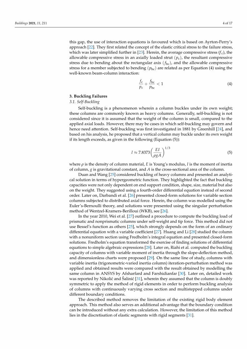
In 1947, using an imaginary column, Shanley concluded that there will be bendingonce the tangent modulus load is exceeded following which axial load increases and reachesa maximum value which lies in between the tangent modulus load and reduced modulusload, and there will be stress reversal once the bending deformation becomes finite. In otherwords, Shanley’s analysis clearly described that the first bifurcation will occur at tangentload and a sequence of equilibrium can be constructed in between two limiting loads,i.e., tangent load and double modulus load. Shanley thus proposed an interaction curve tolink eccentricities to the tangent modulus theory in order to apply his theory for practicalproblem and design calculations [34,35]. In this regard, Figure 3 compares the averagestress for different slenderness ratios, as collected from the experimental investigation of aspecimen (aluminium solid round rod with 0.72 cm diameter having flat ends) discussedin [36].
Later on, a model similar to Shanley was analysed by Johnston by replacing the two-area element with a solid rectangular segment and determined the magnitude of stressdistribution for various loads above the tangent modulus load across the section [37].With the advancement in computer technology, computer programs were written byBatterman [38] to find the maximum load for aluminium alloy H-section with finite webareas about weak as well as the strong axis of bending, in both initially straight positionand with initial curvature [38]. In 1987, Groper and Kenig proposed the inelastic stabilityof stepped columns with the help of Newton’s method or bisection method [39]. In general,the Engesser-Shanley definition for the critical load of a column in an inelastic range is
Buildings 2021, 11, 211 6 of 17
widely acceptable. The same concept is extended for structural steel columns having initialstress due to differential cooling, although the material is in an elastic range.
Buildings 2021, 11, 211 6 of 17
Figure 3. Comparison of experimental data and column theories.
Later on, a model similar to Shanley was analysed by Johnston by replacing the two-area element with a solid rectangular segment and determined the magnitude of stress distribution for various loads above the tangent modulus load across the section [37]. With the advancement in computer technology, computer programs were written by Batterman [38] to find the maximum load for aluminium alloy H-section with finite web areas about weak as well as the strong axis of bending, in both initially straight position and with initial curvature [38]. In 1987, Groper and Kenig proposed the inelastic stability of stepped columns with the help of Newton’s method or bisection method [39]. In general, the Engesser-Shanley definition for the critical load of a column in an inelastic range is widely acceptable. The same concept is extended for structural steel columns having initial stress due to differential cooling, although the material is in an elastic range.
3.3. Failure of Imperfect Long Columns Long columns, more than short ones, are notoriously sensitive to initial imperfec-
tions, defects, etc. Hence, they necessitate careful investigations since a minor change in the loading and geometrical parameters may lead to their sudden failure. It is well ac-cepted that perfect columns are theoretical identities, and in practice, their behaviour is altogether different. One of the important examples of such columns is a walking stick which is subjected to a large amount of eccentricity.
There exists a wide scatter of results for long columns, due to many reasons, and some of the motivations include nonideal supports, plastic behaviour, the interaction of buckling modes (wherein local buckling of columns is more important), along with pos-sible residual stresses. Due to these imperfections, column behaviour is altogether differ-ent practically, in comparison with its theoretical treatment, and the reason for this may be attributed to the treatment of these imperfections. Thus, these columns primarily fail due to elastic instability. Section 4 reports further details about the failure of imperfect long columns.
4. Imperfections in Long Columns 4.1. Imperfections Due to Large Deformations
It is well understood that Euler's original formulation was based on some defined assumptions, and hence, he modelled the behaviour of ideal columns which hardly exist in the reality of the structures. In order to apply his theories to practical problems of en-gineering, it becomes important to understand the difference in the behaviour of a real and an ideal column. This result can be achieved by removing the various assumptions,
0 20 40 60 80 100 120 1400
5
10
15
20
25
30
35
40
45
50
Aver
age
Col
umn
Stre
ss ×
10_3
psi
Slenderness Ratio, L/ρ
17 ST SOLID ROUND ROD, 0.282 INCH DIAMETER FLAT ENDS
Euler's Equation
Tangent Modulus Equation
Reduced Modulus Equation
Figure 3. Comparison of experimental data and column theories.
3.3. Failure of Imperfect Long Columns
Long columns, more than short ones, are notoriously sensitive to initial imperfections,defects, etc. Hence, they necessitate careful investigations since a minor change in theloading and geometrical parameters may lead to their sudden failure. It is well acceptedthat perfect columns are theoretical identities, and in practice, their behaviour is altogetherdifferent. One of the important examples of such columns is a walking stick which issubjected to a large amount of eccentricity.
There exists a wide scatter of results for long columns, due to many reasons, and someof the motivations include nonideal supports, plastic behaviour, the interaction of bucklingmodes (wherein local buckling of columns is more important), along with possible residualstresses. Due to these imperfections, column behaviour is altogether different practically,in comparison with its theoretical treatment, and the reason for this may be attributedto the treatment of these imperfections. Thus, these columns primarily fail due to elasticinstability. Section 4 reports further details about the failure of imperfect long columns.
4. Imperfections in Long Columns4.1. Imperfections Due to Large Deformations
It is well understood that Euler’s original formulation was based on some definedassumptions, and hence, he modelled the behaviour of ideal columns which hardly existin the reality of the structures. In order to apply his theories to practical problems ofengineering, it becomes important to understand the difference in the behaviour of a realand an ideal column. This result can be achieved by removing the various assumptions,one by one, and then analysing the column response. One of the prominent assumptions inEuler’s theory, for example, is that all deformations are considered as “small”. This resultsin curvature (1/R) of deflected shape of a column of length (L) with flexural rigidity (EI),subjected to axial load (P), with pinned boundary condition on either edge becomes equalto double differentiation of deflection (y′′), thus neglecting (y′), as in the following [40]given by Equations (9) and (10) as:
δ
L=
2p
π√
PPcr
(9)
p = sin(α/2) (10)
where α is the slope of deflected shape at support, and Equation (9) represents the solutionin terms of mid-height deflection, δ, applied load, P, and Euler load, Pcr.

Buildings 2021, 11, 211 7 of 17
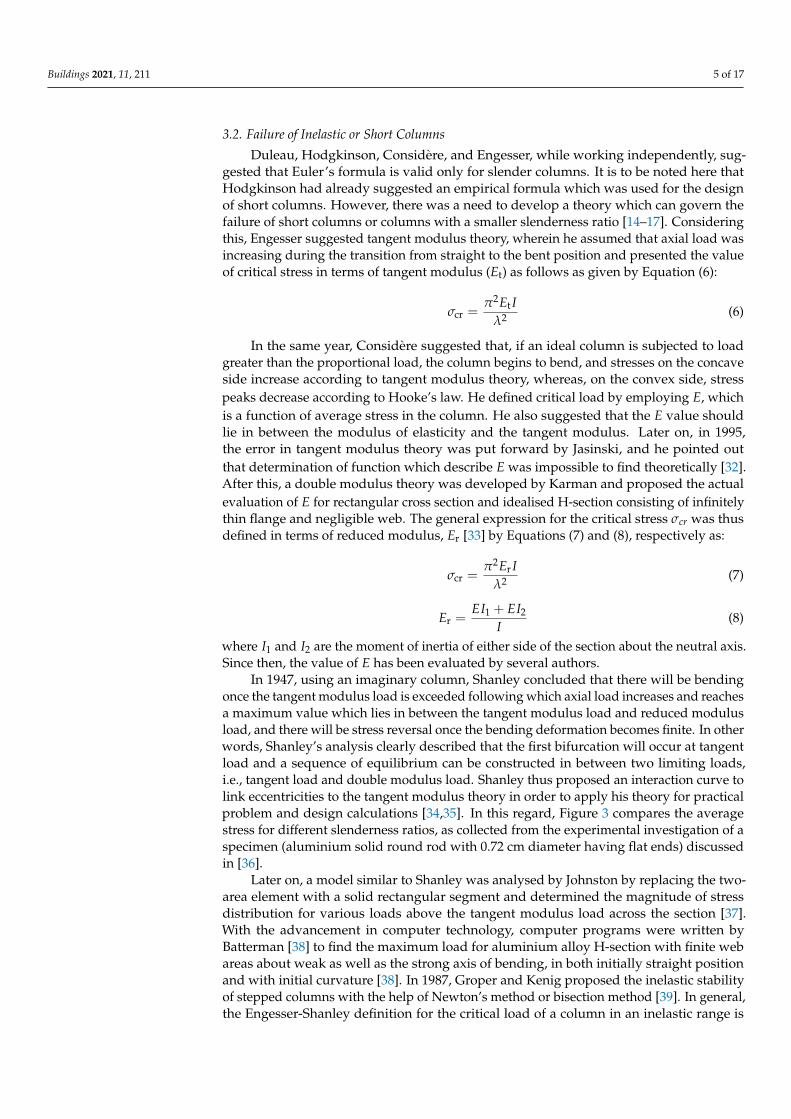
According to [40], Figure 4 shows the variation of P/Pcr with δ/L and highlights thatthe estimation of the expected critical load by linear theory is valid for a considerable rangeof deformations. The reason for such a behaviour is attributed to the fact that for most ofthe columns, a combination of bending and axial stresses reaches the proportionality limitlong before the difference between linear and nonlinear theory becomes notable.
Buildings 2021, 11, 211 7 of 17
one by one, and then analysing the column response. One of the prominent assumptions in Euler’s theory, for example, is that all deformations are considered as “small”. This results in curvature (1/R) of deflected shape of a column of length (L) with flexural rigidity (EI), subjected to axial load (P), with pinned boundary condition on either edge becomes equal to double differentiation of deflection (𝑦′′), thus neglecting (𝑦′), as in the following [40] given by Equations (9) and (10) as: δ𝐿 = 2𝑝𝜋 𝑃 𝑃 (9)
𝑝 = 𝑠𝑖𝑛( 𝛼/2) (10)
where 𝛼 is the slope of deflected shape at support, and Equation (9) represents the solu-tion in terms of mid-height deflection, δ, applied load, P, and Euler load, 𝑃 .
According to [40], Figure 4 shows the variation of P/Pcr with δ/L and highlights that the estimation of the expected critical load by linear theory is valid for a considerable range of deformations. The reason for such a behaviour is attributed to the fact that for most of the columns, a combination of bending and axial stresses reaches the proportion-ality limit long before the difference between linear and nonlinear theory becomes nota-ble.
Figure 4. Normalised load-deflection curve.
4.2. Imperfections Due to Initial Curvature and Eccentric Loading It was Young who, in 1807, tried to find out the effect of eccentricity (e) and initial
curvature on the load-carrying capacity of a given column [41]. However, his original re-search results were not presented in usable form. Later on, during the year 1858, Scheffler [42] presented the complete solution for eccentrically loaded columns, by taking into ac-count the effect of direct stress and bending stress. This solution is now commonly known as the “Secant Formula” (SF).
It is important to highlight, in this context, that the SF is accurate until the predicted stresses are within the elastic limit of the constructional material in use. The behaviour of a column with a given initial curvature or a column subjected to eccentric load is more or less the same, considering the fact that, in either case, the behaviour of the column is the same. Further, if the initial imperfections are small, the original Euler’s formula results in a fairly accurate estimation of the total compressive load which a straight slender member can support. 𝑃𝑃 = 2𝜋 𝑐𝑜𝑠 11 + δ/𝑒 (11)
Figure 4. Normalised load-deflection curve.
4.2. Imperfections Due to Initial Curvature and Eccentric Loading
It was Young who, in 1807, tried to find out the effect of eccentricity (e) and initial cur-vature on the load-carrying capacity of a given column [41]. However, his original researchresults were not presented in usable form. Later on, during the year 1858, Scheffler [42]presented the complete solution for eccentrically loaded columns, by taking into accountthe effect of direct stress and bending stress. This solution is now commonly known as the“Secant Formula” (SF).
It is important to highlight, in this context, that the SF is accurate until the predictedstresses are within the elastic limit of the constructional material in use. The behaviour of acolumn with a given initial curvature or a column subjected to eccentric load is more orless the same, considering the fact that, in either case, the behaviour of the column is thesame. Further, if the initial imperfections are small, the original Euler’s formula results in afairly accurate estimation of the total compressive load which a straight slender membercan support.
PPcr
=
[2π
cos−1{
11 + δ/e
}]2(11)
PPcr
= 1− aδ
(12)
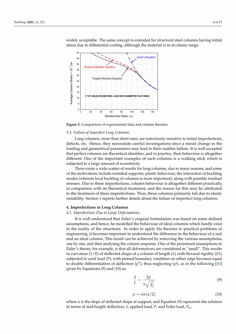
Equations (11) and (12), in this regard, describe the correlation between the Euler’sload for an ideal column (Pcr) and the critical load (P) for a column either having a certaininitial curvature (a) or subjected to eccentric loading (e). Figure 5 shows the graphicalinterpretation of Equations (11) and (12) for different values of eccentricity and initialcurvature. The example calculations are carried out by taking into account Equations (11)and (12) by assuming the different values of δ, along with a and e to consider the initialcurvature or eccentricity, respectively.
Along with that, the graph also shows that it does not matter how the initial imperfec-tion is introduced in a perfect column, given that the critical load for an imperfect columnwill always be smaller than the critical load of the perfect one.

Buildings 2021, 11, 211 8 of 17
Buildings 2021, 11, 211 8 of 17
𝑃𝑃 = 1 − 𝑎 δ (12)
Equations (11) and (12), in this regard, describe the correlation between the Euler’s load for an ideal column (Pcr) and the critical load (P) for a column either having a certain initial curvature (a) or subjected to eccentric loading (e). Figure 5 shows the graphical in-terpretation of Equations (11) and (12) for different values of eccentricity and initial cur-vature. The example calculations are carried out by taking into account Equations (11) and (12) by assuming the different values of δ, along with a and e to consider the initial curva-ture or eccentricity, respectively.
Along with that, the graph also shows that it does not matter how the initial imper-fection is introduced in a perfect column, given that the critical load for an imperfect col-umn will always be smaller than the critical load of the perfect one.
Figure 5. Normalised load versus deflection curves for a compressed member affected by various amplitudes of initial imperfection.
4.3. Imperfections Due to Variable Stiffness Euler formula is derived for prismatic sections and in an attempt to increase the buck-
ling capacity of columns, the researcher focused on the use of nonprismatic sections. This results in a variable moment of inertia (I) along the longitudinal axis. It is to be noted that columns with nonprismatic sections can be studied in two ways, as shown in Figure 6. Among these two major approaches, it can be noticed that several researchers employed a continuum approach using different functions and variables to report closed-form solu-tions. At the same time, other researchers employed numerical approaches/approximate methods to arrive at acceptable solutions.
Finally, it is also well accepted that a given uniform section column is overdesigned everywhere, except the point at which the maximum bending moment occurs, and in need to optimise the buckling capacity of the column, some material can be taken out from the overdesigned section and placed at the point at which the maximum moment is occurring. A number of scientists developed this idea as reported in Table 1. The overall research efforts conducted by several researchers in understanding the behaviour of nonprismatic columns using the two major approaches from Figure 6 are summarised in Table 1, with evidence of methods and outcomes.
Figure 5. Normalised load versus deflection curves for a compressed member affected by variousamplitudes of initial imperfection.
4.3. Imperfections Due to Variable Stiffness
Euler formula is derived for prismatic sections and in an attempt to increase thebuckling capacity of columns, the researcher focused on the use of nonprismatic sections.This results in a variable moment of inertia (I) along the longitudinal axis. It is to be notedthat columns with nonprismatic sections can be studied in two ways, as shown in Figure 6.Among these two major approaches, it can be noticed that several researchers employed acontinuum approach using different functions and variables to report closed-form solutions.At the same time, other researchers employed numerical approaches/approximate methodsto arrive at acceptable solutions.
Buildings 2021, 11, 211 9 of 17
Figure 6. Approaches for the solution of nonprismatic columns.
Table 1. Summary of research on nonprismatic columns using continuum or numerical approaches.
Ref. Variable/Method Column Remarks/Findings
[12] Exponential variation of flex-
ural rigidity using power func-tion
Variable stiffness • First to try the solution with variable stiffness
[43] Exponential variation of flex-
ural rigidity using Bessel’s function
Variable stiffness • Solution based on exponential variation of flex-
ural stiffness using power function, as suggested by [12]
[44] Varying sectional dimension
h(x) and second moment of in-ertia i(x)
Tapered
• Developed equations and design curves for cal-culating the critical buckling
• Analysed columns with many different cross sec-tions
• Four different fixity conditions, i.e., fixed-free, pinned-pinned, fixed-pinned, and fixed-fixed were analysed
[45] ODE approach Variable stiffness • Unsuccessful attempt to maximise the optimum shape
[46] ODE approach Variable stiffness
• Repeated the problem of Lagrange [45] for a can-tilever column
• Proposed the circular section as the optimum for columns with pinned ends
[47] * Variational technique
Twisted; arbitrary cross sec-
tion; pinned ends
• Investigated the study by [46] • Showed that the strongest column is character-
ised by equilateral section and a tapered shape along the length (thickest at mid-span and thin-nest at ends)
• By changing the shape from circular to equilat-eral triangle, the buckling capacity increases by +20.9%
• From equilateral triangular shape to tapered, the buckling capacity show an increment of +61.2%, in comparison to the circular column
Figure 6. Approaches for the solution of nonprismatic columns.
Finally, it is also well accepted that a given uniform section column is overdesignedeverywhere, except the point at which the maximum bending moment occurs, and in needto optimise the buckling capacity of the column, some material can be taken out from theoverdesigned section and placed at the point at which the maximum moment is occurring.A number of scientists developed this idea as reported in Table 1. The overall researchefforts conducted by several researchers in understanding the behaviour of nonprismatic

Buildings 2021, 11, 211 9 of 17
columns using the two major approaches from Figure 6 are summarised in Table 1, withevidence of methods and outcomes.
Table 1. Summary of research on nonprismatic columns using continuum or numerical approaches.
Ref. Variable/Method Column Remarks/Findings
[12] Exponential variation of flexural rigidityusing power function Variable stiffness • First to try the solution with variable stiffness
[43] Exponential variation of flexural rigidityusing Bessel’s function Variable stiffness
• Solution based on exponential variation of flexuralstiffness using power function, as suggested by [12]
[44] Varying sectional dimension h(x) and secondmoment of inertia i(x) Tapered
• Developed equations and design curves for calculatingthe critical buckling
• Analysed columns with many different cross sections• Four different fixity conditions, i.e., fixed-free,
pinned-pinned, fixed-pinned, and fixed-fixedwere analysed
[45] ODE approach Variable stiffness • Unsuccessful attempt to maximise the optimum shape
[46] ODE approach Variable stiffness
• Repeated the problem of Lagrange [45] for acantilever column
• Proposed the circular section as the optimum forcolumns with pinned ends
[47] * Variational technique
Twisted;arbitrary cross
section;pinned ends
• Investigated the study by [46]• Showed that the strongest column is characterised by
equilateral section and a tapered shape along the length(thickest at mid-span and thinnest at ends)
• By changing the shape from circular to equilateraltriangle, the buckling capacity increases by +20.9%
• From equilateral triangular shape to tapered, thebuckling capacity show an increment of +61.2%, incomparison to the circular column
• Proof regarding the number of buckled statewas missing
[48] Continuum approach Variable stiffness• Determined the strongest shape for a given length and
volume for which Euler’s load was maximum
[49] Energy approach Variable stiffness• Isoperimetric inequalities used to obtain the solution of
lower bound to maximum eigenvalue for the problemof [48]
[50] Approximate method Uniform ornonuniform shapes
• Buckling capacity of column with varying section(either abrupt or gradual) by utilizing the input givenin [51]
• Method applicable to both symmetrical andnonsymmetrical varying columns
• Method expedient in solving unsymmetricalcolumns only
[52] Experimental verificationUniform circular;tapered circular;
triangular equilateral
• For uniform circular, tapered circular, and triangularequilateral columns, the deviation between measuredpredicted buckling load was −1.2, +3.1, and +10.6%,respectively
• Suggested modifying the column near the ends toprevent material yielding and potentialinelastic buckling
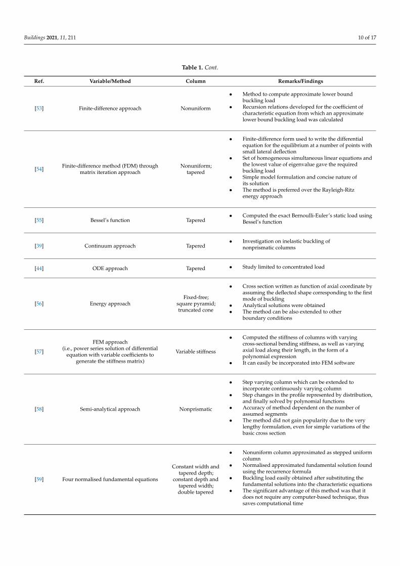
Buildings 2021, 11, 211 10 of 17
Table 1. Cont.
Ref. Variable/Method Column Remarks/Findings
[53] Finite-difference approach Nonuniform
• Method to compute approximate lower boundbuckling load
• Recursion relations developed for the coefficient ofcharacteristic equation from which an approximatelower bound buckling load was calculated
[54] Finite-difference method (FDM) throughmatrix iteration approach
Nonuniform;tapered
• Finite-difference form used to write the differentialequation for the equilibrium at a number of points withsmall lateral deflection
• Set of homogeneous simultaneous linear equations andthe lowest value of eigenvalue gave the requiredbuckling load
• Simple model formulation and concise nature ofits solution
• The method is preferred over the Rayleigh-Ritzenergy approach
[55] Bessel’s function Tapered• Computed the exact Bernoulli-Euler’s static load using
Bessel’s function
[39] Continuum approach Tapered• Investigation on inelastic buckling of
nonprismatic columns
[44] ODE approach Tapered • Study limited to concentrated load
[56] Energy approachFixed-free;
square pyramid;truncated cone
• Cross section written as function of axial coordinate byassuming the deflected shape corresponding to the firstmode of buckling
• Analytical solutions were obtained• The method can be also extended to other
boundary conditions
[57]
FEM approach(i.e., power series solution of differential
equation with variable coefficients togenerate the stiffness matrix)
Variable stiffness
• Computed the stiffness of columns with varyingcross-sectional bending stiffness, as well as varyingaxial load along their length, in the form of apolynomial expression
• It can easily be incorporated into FEM software
[58] Semi-analytical approach Nonprismatic
• Step varying column which can be extended toincorporate continuously varying column
• Step changes in the profile represented by distribution,and finally solved by polynomial functions
• Accuracy of method dependent on the number ofassumed segments
• The method did not gain popularity due to the verylengthy formulation, even for simple variations of thebasic cross section
[59] Four normalised fundamental equations
Constant width andtapered depth;
constant depth andtapered width;double tapered
• Nonuniform column approximated as stepped uniformcolumn
• Normalised approximated fundamental solution foundusing the recurrence formula
• Buckling load easily obtained after substituting thefundamental solutions into the characteristic equations
• The significant advantage of this method was that itdoes not require any computer-based technique, thussaves computational time

Buildings 2021, 11, 211 11 of 17
Table 1. Cont.
Ref. Variable/Method Column Remarks/Findings
[60]
New numerical method(i.e., eigenvalue problem transformedinto a boundary value problem which
can be solved using the numericalintegration)
Nonprismatic;self-weight
• The problem with consideration of distributedaxial force will leave the governing differentialequation with variable coefficient
• For column with variable distributed axial forceor varying cross section the governingdifferential equation cannot be converted intoBessel’s equation
• Numerical method such as energy method, FEM,Finite Difference Method, etc. are required toarrive at solutions
[61] Semi-analytical procedure Nonprismatic
• The method worked well with step discontinuitybut for continuously varying profile minimum 30segments must be considered to obtaincorrect solution
• The procedure can be used to generate geometricstiffness matrix for variable beam-columnelement which can be used in FEM
[62]
Power function or exponential functionand
distribution of flexural stiffness alongwith Bessel’s function
Nonprismatic
• Obtained general solution using the mentionedfunctions
• The general solution can be used to solve theproblem discussed by [32,61,63–65]
[66] ODE approach Variable momentof inertia
• Predicted exact mode shape along with theirclosed-form solution
• Since then, till 1999, no closed-form solutionswere reported for columns with variable momentof inertia subjected to axial load (until [67])
[67] Fixed polynomial variation of flexuralrigidity
Variable momentof inertia
• Solutions similar to [66] considering the fact thatbuckling mode shape was employed aspolynomial function
• Method suggested to generalise solution by [66]
[68] Transcendental equations, Bessel’s orLommel’s function
Variable stiffness;self-weight
• Exact closed-form solutions• Results useful for columns wherein the variation
of elasticity can be constructed
[69] Continuum approach Variable stiffness
• exact solutions for the buckling analysis ofnonuniform columns subjected to concentratedaxial force at different point along thelongitudinal axis
• method exact, simple and efficient• method limited only to very special buckling
mode, and thus not able to solve a column withgeneral heterogeneity
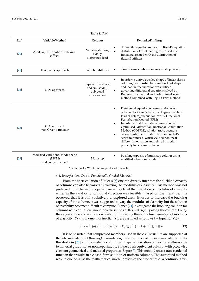
Buildings 2021, 11, 211 12 of 17
Table 1. Cont.
Ref. Variable/Method Column Remarks/Findings
[70] Arbitrary distribution of flexuralstiffness
Variable stiffness;axially
distributed load
• differential equation reduced to Bessel’s equation• distribution of axial loading expressed as a
functional related with the distribution offlexural stiffness
[71] Eigenvalue approach Variable stiffness • closed-form solutions for simple shapes only
[72] ODE approach
Tapered (parabolicand sinusoidal);
polygonalcross section
• In order to derive buckled shape of linear elasticcolumns, relationship between buckled shapeand load in free vibration was utilised
• governing differential equations solved byRunge-Kutta method and determinant searchmethod combined with Regula-Falsi method
[73] ODE approachwith Green’s function
• Differential equation whose solution wasobtained by Green’s Function to give bucklingload of heterogeneous column by FunctionalPerturbation Method (FPM)
• In order to find the material around whichOptimised Differential Functional PerturbationMethod (ODFPM), solution more accurate
• Second-order Perturbation term in Frechet’sseries minimised, which yielded nonlineardifferential equation and related materialproperty to bending stiffness
[29]Modified vibrational mode shape
(MVM)and energy method
Multistep• buckling capacity of multistep column using
modified vibrational mode
* Additionally, Weinberger (unpublished research).
4.4. Imperfections Due to Functionally Graded Material
From the basic equation of Euler’s [5] one can directly infer that the buckling capacityof columns can also be varied by varying the modulus of elasticity. This method was notpreferred until the technology advances to a level that variation of modulus of elasticityeither in the axial or longitudinal direction was feasible. Based on the literature, it isobserved that it is still a relatively unexplored area. In order to increase the bucklingcapacity of the column, it was suggested to vary the modulus of elasticity, but the solutionof instability becomes difficult to compute. Signer [74] investigated the buckling solution forcolumns with continuous monotonic variations of flexural rigidity along the column. Fixingthe origin at one end and x coordinate running along the centre line, variation of modulusof elasticity (E) and moment of inertia (I) were assumed as follows by Equation (13):
E(x)I(x)η(x) = E(0)I(0) = E◦ I◦, η(x) = 1 + β(x), β ∈ R (13)
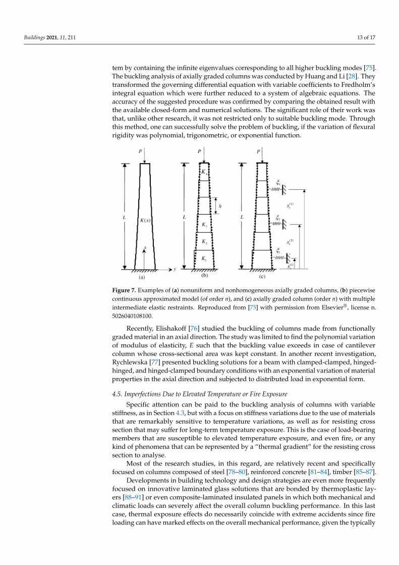
It is to be noted that compressed members used in the civil structure are supported atthe intermediate point (bracing). Considering the importance of the intermediate restraints,the study in [75] approximated a column with spatial variation of flexural stiffness dueto material gradation or nonisoperimetric shape by an equivalent column with piecewiseconstant geometrical and material properties (Figure 7). This method uses a transcendentalfunction that results in a closed-form solution of uniform columns. The suggested methodwas unique because the mathematical model preserves the properties of a continuous sys-
Buildings 2021, 11, 211 13 of 17
tem by containing the infinite eigenvalues corresponding to all higher buckling modes [75].The buckling analysis of axially graded columns was conducted by Huang and Li [28]. Theytransformed the governing differential equation with variable coefficients to Fredholm’sintegral equation which were further reduced to a system of algebraic equations. Theaccuracy of the suggested procedure was confirmed by comparing the obtained result withthe available closed-form and numerical solutions. The significant role of their work wasthat, unlike other research, it was not restricted only to suitable buckling mode. Throughthis method, one can successfully solve the problem of buckling, if the variation of flexuralrigidity was polynomial, trigonometric, or exponential function.
Buildings 2021, 11, 211 13 of 17
transcendental function that results in a closed-form solution of uniform columns. The suggested method was unique because the mathematical model preserves the properties of a continuous system by containing the infinite eigenvalues corresponding to all higher buckling modes [75]. The buckling analysis of axially graded columns was conducted by Huang and Li [28]. They transformed the governing differential equation with variable coefficients to Fredholm’s integral equation which were further reduced to a system of algebraic equations. The accuracy of the suggested procedure was confirmed by compar-ing the obtained result with the available closed-form and numerical solutions. The sig-nificant role of their work was that, unlike other research, it was not restricted only to suitable buckling mode. Through this method, one can successfully solve the problem of buckling, if the variation of flexural rigidity was polynomial, trigonometric, or exponen-tial function.
Recently, Elishakoff [76] studied the buckling of columns made from functionally graded material in an axial direction. The study was limited to find the polynomial varia-tion of modulus of elasticity, E such that the buckling value exceeds in case of cantilever column whose cross-sectional area was kept constant. In another recent investigation, Rychlewska [77] presented buckling solutions for a beam with clamped-clamped, hinged-hinged, and hinged-clamped boundary conditions with an exponential variation of mate-rial properties in the axial direction and subjected to distributed load in exponential form.
Figure 7. Examples of (a) nonuniform and nonhomogeneous axially graded columns, (b) piece-wise continuous approximated model (of order n), and (c) axially graded column (order n) with multiple intermediate elastic restraints. Reproduced from [75] with permission from Elsevier, license n. 5026040108100.
4.5. Imperfections Due to Elevated Temperature or Fire Exposure Specific attention can be paid to the buckling analysis of columns with variable stiff-
ness, as in Section 4.3, but with a focus on stiffness variations due to the use of materials that are remarkably sensitive to temperature variations, as well as for resisting cross sec-tion that may suffer for long-term temperature exposure. This is the case of load-bearing members that are susceptible to elevated temperature exposure, and even fire, or any kind of phenomena that can be represented by a “thermal gradient” for the resisting cross sec-tion to analyse.
Most of the research studies, in this regard, are relatively recent and specifically fo-cused on columns composed of steel [78–80], reinforced concrete [81–84], timber [85–87].
Developments in building technology and design strategies are even more frequently focused on innovative laminated glass solutions that are bonded by thermoplastic layers [88–91] or even composite-laminated insulated panels in which both mechanical and
Figure 7. Examples of (a) nonuniform and nonhomogeneous axially graded columns, (b) piecewisecontinuous approximated model (of order n), and (c) axially graded column (order n) with multipleintermediate elastic restraints. Reproduced from [75] with permission from Elsevier®, license n.5026040108100.
Recently, Elishakoff [76] studied the buckling of columns made from functionallygraded material in an axial direction. The study was limited to find the polynomial variationof modulus of elasticity, E such that the buckling value exceeds in case of cantilevercolumn whose cross-sectional area was kept constant. In another recent investigation,Rychlewska [77] presented buckling solutions for a beam with clamped-clamped, hinged-hinged, and hinged-clamped boundary conditions with an exponential variation of materialproperties in the axial direction and subjected to distributed load in exponential form.
4.5. Imperfections Due to Elevated Temperature or Fire Exposure
Specific attention can be paid to the buckling analysis of columns with variablestiffness, as in Section 4.3, but with a focus on stiffness variations due to the use of materialsthat are remarkably sensitive to temperature variations, as well as for resisting crosssection that may suffer for long-term temperature exposure. This is the case of load-bearingmembers that are susceptible to elevated temperature exposure, and even fire, or anykind of phenomena that can be represented by a “thermal gradient” for the resisting crosssection to analyse.
Most of the research studies, in this regard, are relatively recent and specificallyfocused on columns composed of steel [78–80], reinforced concrete [81–84], timber [85–87].
Developments in building technology and design strategies are even more frequentlyfocused on innovative laminated glass solutions that are bonded by thermoplastic lay-ers [88–91] or even composite-laminated insulated panels in which both mechanical andclimatic loads can severely affect the overall column buckling performance. In this lastcase, thermal exposure effects do necessarily coincide with extreme accidents since fireloading can have marked effects on the overall mechanical performance, given the typically
Buildings 2021, 11, 211 14 of 17
small thickness that is of common use in structural glass applications. Besides differentmaterials and characteristics that are used for these members, the common aspect of theabove documents is represented by the progressive bending weakness deriving from thedegradation of the constituent materials. Therefore, the total compressive load acts on aresisting section and member that prematurely collapses due to its lack of load-bearingcapacity. From a practical point of view, the shared feature for the cited literature studies isthe basic trend to define standardised design buckling curves for columns made of mostlydifferent constructional materials and thus to collect, in a simplified and univocal formu-lation, all the possible uncertainties and effects due to material behaviours, eccentricities,imperfections [92].
Even more attention is indeed required for load-bearing members in general thatcan be subjected to scattered thermal patterns and are thus potentially characterised by anumber of critical cross sections.
Additionally, in this latter case, the first efforts are certainly related to the classicalmaterial for buildings, thus steel members. Alpsten [93] showed, for example, that residualnonuniform thermal stresses can severely affect the column buckling performance of agiven member and result in even more pronounced degradation than geometrical initialimperfections. Culver [94] also focused on the analysis of pinned columns with thermal ex-posure. The study proved that severe thermal gradients in the mid-span region of columnsare typically associated with a remarkable loss of global buckling capacity. While such aconcept can be intuitive—due to stiffness reduction—this is in contrast with the discussionby Hoffend [95]. The reason is in the idealisation of the thermal gradient profile. The gener-ally recognised idea, finally, is that thermal gradient effects can be generally schematised inthe form of an equivalent initial imperfection. Therefore, the overall buckling performanceof an axially loaded member in compression can be severely compromised. On the otherhand, this issue can be efficiently addressed for safe design by means of conventionalcalculation methods that include a given initial geometrical imperfection.
5. Conclusions
The problem investigated by Euler was much simpler since it did not involve findingthe solution of differential equation with varying coefficient because neither the materialproperties nor the cross-sectional dimensions were changing. However, in an attempt tomaximise the buckling capacity of the column, modifications were performed in the columndue to which the differential equation governing the mathematical model is left with varyingcoefficients. This review paper provides a complete synopsis of the development of varioustheories related to column buckling. A significant number of methods were recalled to obtainclose-form solutions, but providing evidence for each one of them had certain intrinsicrestrictions—either the buckling shape was assumed to be governed by a specific function orthe distribution of flexural stiffness was not random. Moreover, all the discussed methodsin the literature showed rather good agreement with some experimental results availablein the literature. However, which one of them is more suitable to find the solution for agiven arbitrary variation of coefficients still remains an unanswered question. In the self-buckling of columns, more research emphasis is required for the proper discretisation of elasticsegments with rigid segments. For short column analysis, detailed experiments with variousmaterials are one of the areas wherein research still needs to be carried out. In long columnsanalysis, more emphasis shall be put on the development of closed-form solution withvariable moment of inertia with emphasis on varying material properties along the lengthof the column. Further, different functions can be developed to investigate the variationof modulus of elasticity and its effect on the buckling strength of columns. Furthermore,attention is indeed required for load-bearing members in general that can be subjected toscattered thermal patterns and are thus potentially characterised by a number of critical crosssections. This can be achieved by incorporating the effect of thermal gradient in terms ofinitial imperfections.

Buildings 2021, 11, 211 15 of 17
Author Contributions: The reported work is carried out authors as a team wherein Conceptualiza-tion, M.D.G.; methodology, M.D.G. and C.B.; software, A.S.; validation, A.S., A.P.K. and L.M.G.;formal analysis, M.D.G., C.B. and A.S..; investigation, M.D.G., C.B., A.S., A.P.K. and L.M.G.; resources,A.S. and M.D.G.; data curation, M.D.G., C.B. and A.S.; writing—original draft preparation, M.D.G.,C.B. and A.S.; writing—review and editing, M.D.G., C.B., A.P.K. and L.M.G.; visualization, M.D.G.and C.B.; supervision, M.D.G.; project administration, L.M.G.; funding acquisition. All authors haveread and agreed to the published version of the manuscript.
Funding: This research received no external funding.
Institutional Review Board Statement: Not applicable.
Informed Consent Statement: Not applicable.
Data Availability Statement: Data will be available upon request.
Acknowledgments: Authors acknowledge the support and encouragement provided by Director,VNIT Nagpur, India. MDPI is also acknowledged for the invited free-of-charge submission of thismanuscript in the special issue “Innovation in Structural Analysis and Dynamics for Constructions”(C.B. Guest Editor vouchers).
Conflicts of Interest: The authors declare no conflict of interest.
References1. Hooke, R. Lectures de Potentia Restitutiva, or of Spring Explaining the Power of Springing Bodies; John Martyn: London, UK, 1678; pp.
331–388, reprinted, of R. T.Günther, Early Sciences in Oxford 8, Oxford, 1931.2. Hales, T.A.; Pantelides, C.P.; Reavele, L.D. Analytical buckling model for slender FRP-reinforced concrete columns. Compos.
Struct. 2017, 176, 33–42. [CrossRef]3. Cheng, W.-S. Repair and reinforcement of timber columns and shear walls–A review. Constr. Build. Mater. 2015, 97, 14–24.
[CrossRef]4. Bedon, C.; Kalamar, R.; Eliasova, M. Low velocity impact performance investigation on square hollow glass columns via full-scale
experiments and Finite Element analyses. Compos. Struct. 2017, 182, 311–325. [CrossRef]5. Euler, L. Euler’s calculation of buckling loads for columns of non uniform section. In The Rational Mechanics of Flexible or Elastic
Bodies 1638–1788; Orell FüssliTurici, Societatis Scientiarum Naturalium Helveticae: Zurich, Switzerland, 1960; pp. 345–347,Originally published in 1757.
6. Euler, L. De altitudinecolumnarum sub proprioponderecorruentium. Acta Acad. Sci. Petropolitanae 1780, 1, 163–193. (In Latin)7. Euler, L. Determinatioonerum, quaecolumnaegestarevalent. Acta Acad. Sci. Petropolitanae 1947, 1, 121–145. (In Latin)8. Euler, L. Exameninsignispuradoxi in theoria column arumoccurentis. Acta Acad. Sci. Petropolitanae 1780, 1, 146–162. (In Latin)9. Coulomb, C.A. Essai sur une Application des Regles de Maximis et Minimis a Quelques Problemes de Statiquerelatifs a L’architecture;
Academie Royale Des Sciences: Paris, France, 1773; Volume 7, pp. 343–382.10. Dinnik, A.N. Buckling under own weight. Proceeding Don Polytech. 1912, 1, 19. (In Russian)11. Dinnik, A.N. Design of column of varying cross section” Transactions of American Society of Mechanical Engineering. Appl.
Mech. 1929, 51, 105–114.12. Dinnik, A.N. Design of column of varying cross section. Trans. Am. Soc. Mech. Eng. 1932, 54, 105–109.13. van Musschenbroek, P. Physicaeexperimentale Set Geometricae de Magnete, Tuborum Capillarium Vitreorum Quespeculorum Attractione,
Magnitudine terrae, Cohaerentia Corporum Firmorum Dissertationes: Ut et Ephemerides Meteorologicae Ultrajectinae; Luchtmans, NovaEditio: Viennae, Austria, 1756.
14. Duleau, A.J.C. Essaitheorique et Experimental sur la Resistance du Fer Forge; Mme.Ve. Courcier, Nabu Press: Paris, France, 1820.15. Hodgkinson, E. On the Transverse Strain and Strength of Materials. In Memoirs of the Literary and Philosophical Society of Manchester;
2nd Series; Literary and Philosophical Society of Mancheste: Manchester, UK, 1824; Volume 2–4.16. Engesser, F. Ueber die KnickfestigkeitgeraderSUibe. In ZeitschriftfiirArchitektur und Ingenieurwesen; W. Ernst & Sohn: Berlin,
Germany, 1889; Volume 35.17. Considère, A. Résistance des piècescomprimées. In Congrès International des Procédés de Construction; Libraire Polytechnique: Paris,
France, 1891; pp. 3, 371.18. Lamarle, E. Memoire sur la flexion du bois. In Annales des Travaux Publics de Belgique; Vandooren, B.J., Ed.; Imprimeur Des
Annales Des Travaus Publication: Bruxelles, Belgium, 1845; Volume III, pp. 1–64, Volume IV, pp. 1–36.19. Rankine, W.J.M. A Manual of Civil. Engineering; Charles Griffin: London, UK, 1862.20. Young, D.H. Rational design of steel columns. Am. Soc. Civ. Eng. Transl. 1936, 101, 442–500.21. Johnson, J.B.; Bryan, C.W.; Turneaure, F.E. The Theory and Practice of Modern Framed Structures: Designed for the Use of Schools, and
for Engineers in Professional Practice; John Wiley & Sons, Inc.: New York, NY, USA, 1905; p. 561.22. Ayrton, W.E.; Perry, J. On struts. Engineer 1886, 62, 464–465.23. Robertson, A. The strength of struts. Inst. Civ. Eng. 1925, 1. [CrossRef]
Buildings 2021, 11, 211 16 of 17
24. Greenhill, A.G. Determination of the greatest height consistent with stability that a vertical pole or mast can be made, and thegreatest height to which a tree of given proportions can grow. Proc. Camb. Philos. Soc. 1881, 4, 65–73.
25. Duan, W.H.; Wang, C.M. Exact solution for buckling of columns including self-weight. J. Eng. Mech. 2008, 134, 116–119. [CrossRef]26. Darbandi, S.M.; Firouz-Abadi, R.D.; Haddadpour, H. Buckling of variable section column under axial loading. J. Eng. Mech. 2010,
136, 472–476. [CrossRef]27. Wei, D.J.; Yan, S.X.; Zhang, Z.P.; Li, X.-F. Critical load for buckling of non-prismatic columns under self-weight and tip force.
Mech. Res. Commun. 2010, 37, 554–558. [CrossRef]28. Huang, Y.; Li, X.F. Buckling analysis of nonuniform and axially graded columns with varying flexural rigidity. J. Eng. Mech. 2010,
137, 73–81. [CrossRef]29. Rahai, A.R.; Kazemi, S. Buckling analysis of non-prismatic columns based on modified vibration modes. Commun. Nonlinear Sci.
Numer. Simul. 2008, 13, 1721–1735. [CrossRef]30. Afsharfard, A.; Farshidianfar, A. Finding the buckling load of non-uniform columns using the iteration perturbation method.
Theor. Appl. Mech. Lett. 2014, 4. [CrossRef]31. Nikolic, A.; Šalinic, S. Buckling analysis of non-prismatic column: A rigid multibody approach. Eng. Struct. 2017, 143, 511–521.
[CrossRef]32. Jasinski, F. NocheinWortzu den Knickfragen. Schweiz. Bauztg. 1895, 25, 172.33. von Karman, T. Untersuchungen Liber Knickfestigkeit; Mitteilungeniiber Forsclulflgsarbeitenaufdem Gebiete des Ingenieul’lvesens:
Berlin, Germany, 1910.34. Shanley, F.R. The column paradox. J. Aeronaut. Sci. 1946, 13, 618–679. [CrossRef]35. Shanley, F.R. Inelastic column theory. J. Aeronaut. Sci. 1947, 14, 261–268. [CrossRef]36. Templin, R.L.; Strum, R.G.; Hartmann, E.C.; Holt, M. Column strength of various aluminium alloys. In Aluminium Research
Laboratories Technical Paper 1; Aluminium Company of America: Pittsburgh, PA, USA, 1938.37. Johnston, B.G. Buckling behavior above the tangent modulus load. J. Eng. Mech. Div. ASCE 1961, 87, 79–100. [CrossRef]38. Batterman, R.H.; Johnston, B.G. Behavior and maximum strength of metal columns. J. Struct. Div. ASCE 1967, 93, 205–230.
[CrossRef]39. Groper, M.; Kenig, M.J. Inelastic buckling of nonprismatic column. J. Eng. Mech. 1987, 113, 1233–1239. [CrossRef]40. Chajes, A. Principles of Structural Stability; Prentice Hall: Hoboken, NJ, USA, 1974.41. Young, T. A Course of Lectures on Natural Philosophy and the Mechanical Arts; Royal Society: London, UK, 1807; Volume 1, 2,
pp. 135–156.42. Salmon, E.H. Columns by, Frowde; Hodder & Stoughton: London, UK, 1920.43. Murphy, G.M. Ordinary Differential Equations and Their Solutions; D. Van Nostrand: New York, NY, USA, 1960.44. Gere, J.M.; Carter, W.O. Critical buckling loads for tapered columns. J. Struct. Div. Proc. 1962, 1, 1–12.45. Lagrange, J.-L. Sur la figure des colonnes. In Oeuvres de Lagrange (Publ. de M.J.-A. Serret); Gauthier-Villars: Paris, France, 1868;
Volume 2, pp. 125–170.46. Clausen, T. Uber die Form architektonischerSäulen. Bull. Phys. Math. De L’academie St. Petersburg 1851, 9, 368–379.47. Keller, J.B. The shape of the strongest column. Arch. Ration. Mech. Anal. 1960, 5, 275–285. [CrossRef]48. Tadjbakhsh, I.; Keller, J.B. Strongest columns and isoperimetric inequalities for eigenvalues. J. Appl. Mech. 1962, 29, 159–164.
[CrossRef]49. Taylor, J.E. The strongest column: An energy approach. J. Appl. Mech. 1967, 34, 486–487. [CrossRef]50. Martin, G.H. A procedure for determining the critical load for a column of varying section. J. Aeronaut. Sci. 1946, 13, 135–140.
[CrossRef]51. Harris, C.O. A suggestion for columns of varying section. J. Aeronaut. Sci. 1942, 9. [CrossRef]52. Wilson, J.F.; Holloway, D.M.; Biggers, S.B. Stability experiments on the strongest columns and circular arches. Exp. Mech. 1971, 11,
303–308. [CrossRef]53. O’Rourke, M.; Zebrowski, T. Buckling load for nonuniform columns. Comput. Struct. 1977, 7, 717–720. [CrossRef]54. Iremonger, M.J. Finite difference buckling analysis of non-uniform columns. Comput. Struct. 1980, 12, 741–748. [CrossRef]55. Banerjee, J.R.; Williams, F.W. Exact Bernoulli-Euler static stiffness matrix for a range of tapered beam-columns. Int. J. Numer.
Methods Eng. 1985, 21, 2289–2302. [CrossRef]56. Smith, W.G. Analytic solutions for tapered column buckling. Comput. Struct. 1988, 28, 677–681. [CrossRef]57. Chen, Y.Z.; Cheung, Y.K.; Xie, J.R. Buckling loads of columns with varying cross-section. J. Eng. Mech. 1989, 115, 662–667.
[CrossRef]58. Eisenberger, M. Buckling loads for variable cross-section members with variable axial forces. Int. J. Solids Struct. 1991, 27, 135–143.
[CrossRef]59. Lee, S.Y.; Kuo, Y.H. Elastic stability of non-uniform column. J. Sound Vib. 1991, 148, 11–24. [CrossRef]60. Vaziri, H.H.; Xie, J. Buckling of columns under variably distributed axial loads. Comput. Struct. 1992, 45, 505–509. [CrossRef]61. Arbabi, F.; Li, F. Buckling of variable cross-section columns: Integral-equation approach. J. Struct. Eng. 1991, 117, 2426–2441.
[CrossRef]62. Qiusheng, L.; Hong, C.; Guiqing, L. Stability analysis of bars with varying cross-section. Int. J. Solids Struct. 1995, 32, 3217–3228.
[CrossRef]

Buildings 2021, 11, 211 17 of 17
63. Timoshenko, S.P.; Gere, J.M. Theory of Elastic Stability; McGraw Hill: New York, NY, USA, 1961.64. Genik, A.N. Scientific Paper of Genik; AN: Moscow, Russia, 1950.65. von Kármán, T.; Biot, M. Mathematical Methods in Engineering; McGraw-Hill: New York, NY, USA, 1940.66. Duncan, W.J. Galerkin’s Method in Mechanics and Differential Equations; Aeronautical Research Committee Reports and Memoranda;
H.M.S.O.: London, UK, 1937; No. 1798.67. Elishakoff, I.; Rollot, O. New closed-form solutions for buckling of a variable stiffness column by mathematica. J. Sound Vib. 1999,
224, 172–182. [CrossRef]68. Elishakoff, I. A closed form solution for the generalized Euler problem. Proc. R. Soc. Lond. A Math. Phys. Eng. Sci. 2000, 456.
[CrossRef]69. Li, Q.S. Buckling analysis of multi-step non-uniform columns. Adv. Struct. Eng. 2000, 3, 139–144. [CrossRef]70. Li, Q.S. Exact solutions for buckling of non-uniform column under axial concentrated and distributed loading. Eur. J. Mech.-
A/Solids 2001, 20, 485–500. [CrossRef]71. Wang, C.M.; Wang, C.Y.; Reddy, J.N. Exact Solutions for Buckling of Structural Members; CRC: Boca Raton, FL, USA, 2005.72. Lee, B.K.; Carr, A.J.; Lee, T.E.; Kim, J. Buckling loads of columns with constant volume. J. Sound Vib. 2006, 294, 381–387. [CrossRef]73. Totry, E.M.; Altus, E.; Proskura, A. Buckling of non-uniform beams by a direct functional perturbation method. Probabilistic Eng.
Mech. 2007, 22, 88–89. [CrossRef]74. Siginer, A. Buckling of columns of variable flexural rigidity. J. Eng. Mech. 1992, 118, 640–643. [CrossRef]75. Singh, K.V.; Li, G. Buckling of functionally graded and elastically restrained non-uniform columns. Compos. Part B Eng. 2009,
40, 393–403. [CrossRef]76. Elishakoff, I. Buckling of a column made of functionally graded material. Arch. Appl. Mech. 2012, 82, 1355–1360. [CrossRef]77. Rychlewska, J. Buckling analysis of axially functionally graded beams. J. Appl. Math. Comput. Mech. 2014, 13, 103–108. [CrossRef]78. Janss, J.; Minne, R. Buckling of steel columns in fire conditions. Fire Saf. J. 1981, 4, 227–235. [CrossRef]79. Ng, K.T.; Gardner, L. Buckling of stainless steel columns and beams in fire. Eng. Struct. 2007, 29, 717–730. [CrossRef]80. Gomes, F.C.T.; Providencia e Costa, P.M.; Rodrigues, J.P.C.; Neves, I.C. Buckling length of a steel column for fire design. Eng.
Struct. 2007, 29, 2497–2502. [CrossRef]81. Tie, L.L. Fire Resistance of Reinforced Concrete Columns: A Parametric Study. J. Fire Prot. Eng. 1989, 1, 121–129.82. Rodrigues, J.P.C.; Laím, L.; Correia, A.M. Behaviour of fiber reinforced concrete columns in fire. Compos. Struct. 2010, 92, 1263–1268.
[CrossRef]83. Han, L.H.; Tan, Q.-H.; Song, T.-Y. Fire Performance of Steel Reinforced Concrete Columns. J. Struct. Eng. 2015, 141. [CrossRef]84. Gernay, T. Fire resistance and burnout resistance of reinforced concrete columns. Fire Saf. J. 2019, 104, 67–78. [CrossRef]85. Malhotra, H.L.; Rogowski, B.F. Fire resistance of laminated timber columns. Fire Res. Notes 1967, 671, 1–60.86. Schnabl, S.; Turk, G.; Planinc, I. Buckling of timber columns exposed to fire. Fire Saf. J. 2011, 46, 431–439. [CrossRef]87. Wiesner, F.; Bisby, L. The structural capacity of laminated timber compression elements in fire: A meta-analysis. Fire Saf. J. 2019,
107, 114–125. [CrossRef]88. Amadio, C.; Bedon, C. Buckling of Laminated Glass Elements in Compression. J. Struct. Eng. 2011, 137. [CrossRef]89. Oikonomopoulou, F.; van den Broek, E.A.M.; Bristogianni, T.; Veer, F.A.; Nijsse, R. Design and experimental testing of the bundled
glass column. Glass Struct. Eng. 2017, 2, 183–200. [CrossRef]90. Aiello, S.; Campione, G.; Minafo, G.; Scibilia, N. Compressive behaviour of laminated structural glass members. Eng. Struct. 2011,
33, 3402–3408. [CrossRef]91. Bedon, C.; Amadio, C. Buckling analysis and design proposal for 2-side supported double Insulated Glass Units (IGUs) in
compression. Eng. Struct. 2018, 168, 23–34. [CrossRef]92. Bedon, C.; Amadio, C. Design buckling curves forglass columns and beams. Struct. Build. 2015, 168, 514–526. [CrossRef]93. Alpsten, G.A. On numerisk simulering av barformagan hos isolerade stalpelareutsatta for brandpaverkan. In Nordiskafrosknings-
dagar for Stalbygguad; ETH, Zurich: Stockholm, Sweden, 1970. (In German)94. Culver, C.G. Steel column buckling under thermal gradient. ASCE J. Struct. Div. 1972, 92, 1853–1865. [CrossRef]95. Hoffend, F. Brandverhalten von Stahlstutzenbeiausmittiger Lasteintung. In Dehnbehindeung ode teilweiser Beckleidun; Sonder-
forschungsbereich 148, Brandverhalten von Bauteilen, Arbeitsbericht, Teil; VS Verlag für Sozialwissenschaften, WiesbadenTechnical University: Wiesbaden, Germany, 1978–1980. (In German)