1 axis pulse positioning control module eh-pos · industrial equipment systems co., ltd. constantly...
TRANSCRIPT

HITACHI PROGRAMMABLE CONTROLLER
1 Axis Pulse PositioningControl Module
EH-POS
APPLICATION MANUAL
NJI-315(x)
WARNING
To ensure that the equipment described by this manual. As well as all equipment connected to and used with it, operate satisfactorily and safety, all applicable local and national codes that apply to installing and operating the equipment must be followed. Since codes can vary geographically and can change with time, it is the user’s responsibility to determine which standard and codes apply, and to comply with them.
FAILURE TO COMPLY WITH APPLICABLE CODES AND STANDARDS CAN RESULT IN DAMAGE TO EQUIPMENT AND/OR SERIOUS INJURY TO PERSONNEL. INSTALL EMARGENCY POWER STOP SWITCH, WHICH OPERATES INDEPENDENTLY OF THE PROGRAMMABLE CONTROLLER TO PROTECT THE EQUIPMENT AND/OR PERSONNEL IN CASE OF THE CONTROLLER MALFUNCTION.
Personnel who are to install and operate the equipment should carefully study this manual and any other referred to by it prior to installation and/or operation of the equipment. Hitachi Industrial Equipment Systems Co., Ltd. constantly strives to improve its products, and the equipment and the manual(s) that describe it may be different from those already in your possession.
If you have any questions regarding the installation and operation of the equipment, or if more information is desired, contact your local Authorized Distributor or Hitachi Industrial Equipment Systems Co., Ltd.
IMPORTANT THIS EQUIPMENT GENERATES, USES, AND CAN RADIATE RADIO FREQUENCY ENERGY AND, IF NOT INSTALLED AND USED IN ACCORDANCE WITH THE INSTRUCTION MANUAL, MAY CAUSE INTERFERENCE TO RADIO COMMUNICATIONS. AS TEMPORARILY PERMITTED BY REGULATION, IT HAS NOT BEEN TESTED FOR COMPLIANCE WITH THE LIMITS FOR CLASS A COMPUTING DEVICES PURSUANT TO SUBPART J OF PART 15 OF FCC ROULES, WHICH ARE DESIGNED TO PROVIDE PEASONABLE PROTECTION AGAINST SUCH INTERFERENCE.
OPERATION OF THIS EQUIPMENT IN A RESIDENTIAL AREA IS LIKELY TO CAUSE INTERFERENCE IN WHICH CASE THE USER, AT HIS OWN EXPENSE, WILL BE REQUIRED TO TAKE WHATEVER MEASURES MAY BE REQUIRED TO CORRECT THE INTERFERENCE.

LIMITED WARRANTY AND IMITATION OF LIABILITY
Hitachi Industrial Equipment Systems Co., Ltd. (Hitachi) warrants to the original purchaser that the programmable logic controller (PLC) manufactured by Hitachi is free from defects in material and workmanship under normal use and service. The obligation of Hitachi under this warranty shall be limited to the repair or exchange of any part or parts which may prove defective under normal use and service within eighteen (18) months from the date of manufacture or twelve (12) months from the date of installation by the original purchaser which ever occurs first, such defect to be disclosed to the satisfaction of Hitachi after examination by Hitachi of the allegedly defective part or parts. This warranty in expressly in lieu of all other warranties expressed or implied including the warranties of merchantability and fitness for use and of all other obligations or liabilities and Hitachi neither assumes, nor authorizes any other person to assume for Hitachi, any other liability in connection with the sale of this PLC. This warranty shall not apply to this PLC or any part hereof which has been subject to accident, negligence, alternation, abuse, or misuse. Hitachi makes no warranty whatsoever in respect to accessories or parts not supplied by Hitachi. The term “original purchaser”, as used in this warranty, shall be deemed to mean that person for whom the PLC in originally installed. In no event, whether as a result of breach of contract, warranty, tort (including negligence) or otherwise, shall Hitachi or its suppliers be liable for any special, consequential, incidental or penal damages including but not limited to, loss or profit or revenues, loss of use of the products or any associated equipment, damage to associated equipment, cost of capital, cost of substitute products, facilities, services or replacement power, down time costs, or claims of original purchaser’s customers for such damages. To obtain warranty service, return the product to your distributor, or send it with a description of the problem, proof of purchase, post paid, insured, and in a suitable package to:
Quality Assurance Dept. Hitachi Industrial Equipment Systems Co., Ltd. 46-1 Ooaza-Tomioka Nakajo-machi Kitakanbara-gun, Niigata-ken 959-2608 JAPAN

Copyright 2002 by Hitachi Industrial Equipment Systems Co., Ltd. All Right Reserved – Printed in Japan
The Information and/or drawing set forth in this document and all right in and to inventions disclosed herein and patent which might be granted thereon disclosing or employing and the materials, methods, techniques or apparatus described herein are the exclusive property of Hitachi Industrial Equipment Systems Co., Ltd .
No copies of the information or drawings shall be made without the prior constant of Hitachi Industrial Equipment Systems Co., Ltd.
Hitachi Industrial Equipment Systems Co., Ltd. provides customer assistance in varied technical areas. Since Hitachi does not possess full access to data concerning all of the uses and applications of customer’s products, responsibility is assumed by Hitachi neither for customer product design nor for any infringement of patents or rights of others, which may result from Hitachi assistance.
The specifications and descriptions contained in this manual were accurate at the time they were approved for printing. Since Hitachi Industrial Equipment Systems Co., Ltd. Incorporated constantly strives to improve all its products, we reserve the right to make changes to equipment and/or manual at any time without notice and without incurring any obligation other than as noted in this manual.
Hitachi Industrial Equipment Systems Co., Ltd. assumes no responsibility for errors that may appear in this manual.
As the product works with user program, and Hitachi Industrial Equipment Systems Co., Ltd. cannot test all combination of user program components, it is assumed that a bug or bugs may happen unintentionally. If it is happened: please inform the fact to Hitachi Industrial Equipment Systems Co., Ltd. or its representative. Hitachi will try to find the reason as much as possible and inform the countermeasure when obtained.
Nevertheless Hitachi Industrial Equipment Systems Co., Ltd. intends to make products with enough reliability, the product has possibility to be damaged at any time. Therefore personnel who are to install and operate the equipment have to prepare with the countermeasure such as power off switch can be operated independently of the controller. Otherwise, it can result in damage to equipment and/or serious injury to personnel.

Safety Precautions
Read this manual and related documents thoroughly before installing, operating, performing preventive maintenance or performing
inspection, and be sure to use the unit correctly. Use this product after acquiring adequate knowledge of the unit, all safety
information, and all cautionary information. Also, make sure this manual enters the possession of the chief person in charge of safety
maintenance.
Safety caution items are classified as "Danger" and "Caution" in this document.
DANGER: Cases where if handled incorrectly a dangerous circumstance may be created, resulting in
possible death or severe injury.
CAUTION: Cases where if handled incorrectly a dangerous circumstance may be created, resulting in possible
minor to medium injury to the body, or only mechanical damage.
However, depending on the circumstances, items marked with may result in major accidents.
In any case, they both contain important information, so please follow them closely.
Icons for prohibited items and required items are shown below:
: Indicates prohibited items (items that may not be performed). For example, when open flames are prohibited, is shown.
: Indicates required items (items that must be performed). For example, when grounding must be performed,
is
shown.
1. About installation
CAUTION
l Use this product in an environment as described in the catalogue and this document.
If this product is used in an environment subject to high temperature, high humidity, excessive dust, corrosive gases,
vibration or shock, it may result in electric shock, fire or malfunction.
l Perform installation according to this manual.
If installation is not performed adequately, it may result in dropping, malfunction or an operational error in the unit.
l Do not allow foreign objects such as wire chips to enter the unit.
They may become the cause of fire, malfunction or failure.
CAUTION

2. About wiring
REQUIRED
l Always perform grounding (FE terminal).
If grounding is not performed, there is a risk of electric shocks and malfunctions.
CAUTION
l Connect power supply that meets rating.
If a power supply that does not meet rating is connected, fire may be caused.
l The wiring operation should be performed by a qualified personnel.
If wiring is performed incorrectly, it may result in fire, damage, or electric shock.
3. Precautions when using the unit
DANGER
l Do not touch the terminals while the power is on.
There is risk of electric shock.
l Structure the emergency stop circuit, interlock circuit, etc. outside the programmable controller (hereinafter referred to as
PC).
Damage to the equipment or accidents may occur due to failure of the PC.
However, do not interlock the unit to external load via relay drive power supply of the relay output module.
CAUTION
l When performing program change, forced output, RUN, STOP, etc., while the unit is running, be sure to verify safety.
Damage to the equipment or accidents may occur due to operation error.
l Supply power according to the power-up order.
Damage to the equipment or accidents may occur due to malfunctions.

4. About preventive maintenance
DANGER
l Do not connect the , of the battery in reverse. Also, do not charge, disassemble, heat, place in fire, or short circuit the
battery.
There is a risk of explosion or fire.
PROHIBITED
l Do not disassemble or modify the unit.
These actions may result in fire, malfunction, or malfunction.
CAUTION
l Turn off the power supply before removing or attaching module/unit.
Electric shock, malfunction or failure may result.

Table of contents
Chapter 1 Introduction 1-1 to 1-3
1.1 Before Use........................................................................................................................................................1-11.2 Accessaries.......................................................................................................................................................1-21.3 Option................................................................................................................................................................1-3
Chapter 2 Features 2-1
Chapter3 System configuration 3-1 to 3-2
3.1 Structure and Parts name............................................................................................................................3-13.2 System configuration.....................................................................................................................................3-2
Chapter 4 Function and Performance Specifications 4-1 to 4-7
4.1 General Specifications...................................................................................................................................4-14.2 Functional Specifications .............................................................................................................................4-24.3 I/O Interface Specifications...........................................................................................................................4-34.4 Input/output Signal........................................................................................................................................4-54.5 Output Method................................................................................................................................................4-64.6 Name of LED ...................................................................................................................................................4-7
Chapter 5 Trial Run (Simple Operation Example) 5-1 to 5-6
5.1 Items of Trial Run ..........................................................................................................................................5-15.2 Procedure of Trial Run...................................................................................................................................5-1
Chapter 6 Operation Data Setting 6-1 to 6-26
6.1 Operation Data ...............................................................................................................................................6-16.1.1 Common parameter.........................................................................................................................6-16.1.2 Automatic Operation Position data.............................................................................................6-13
6.2 Register configuration and operation data setting.................................................................................6-206.2.1 I/O Allocation.....................................................................................................................................6-206.2.2 I/O register configuration ................................................................................................................6-206.2.3 Status register ( Input register ) Bit Allocation ........................................................................6-216.2.4 Control register ( Output register ) Bit Allocation....................................................................6-22
6.3 Command.........................................................................................................................................................6-236.3.1 Control command .............................................................................................................................6-236.3.2 Communication command..............................................................................................................6-256.3.3 Display command.............................................................................................................................6-26
Chapter 7 Data Setting and Reading 7-1 to 7-5
7.1 Communication sequence.............................................................................................................................7-17.1.1 Setting communication flow ( communication command ) .....................................................7-17.1.2 Reading communication flow ( in case of Display command ) ...............................................7-2
7.2 Communication flow to change current data............................................................................................7-37.3 Handshake sequence .....................................................................................................................................7-4
7.3.1 Communication command..............................................................................................................7-47.3.2 Display command.............................................................................................................................7-47.3.3 Transmission matrix.......................................................................................................................7-5
Chapter 8 Operation 8-1 to 8-17

8.1 Homing Operation..........................................................................................................................................8-18.1.1 Desirable Homing.............................................................................................................................8-28.1.2 Low Speed Homing...........................................................................................................................8-28.1.3 High Seed Homing1 ( Off edge ).....................................................................................................8-48.1.4 High Seed Homing2 ( Marker stop ).............................................................................................8-78.1.5 Home position of Absolute Encoder..............................................................................................8-9
8.2 Manual Operation..........................................................................................................................................8-108.2.1 Manual Operation1 ( Control Mode by External Input ) .........................................................8-108.2.2 Manual Operation2 ( Command Control Mode ) ......................................................................8-11
8.3 Automatic Operation.....................................................................................................................................8-138.3.1 Automatic Operation1 ( One Step Operation ) ..........................................................................8-148.3.2 Automatic Operation2 ( Single cycle Operation )......................................................................8-168.3.3 Automatic Operation3 ( Continuous Cycle Operation )...........................................................8-17
Chapter 9 Positioning Module Installation 9-1 to 9-6
9.1 Loading the Positioning module..................................................................................................................9-19.2 Wiring to the Power supply module............................................................................................................9-29.3 Wiring to the Positioning module ...............................................................................................................9-2
9.3.1 Output wiring ....................................................................................................................................9-29.3.2 Caution of Input / output wiring....................................................................................................9-3
9.4 Example of wiring with a Servo Amplifier................................................................................................9-49.4.1 Example of wiring with Hitachi AD series (increment) ...........................................................9-49.4.2 Example of wiring with Hitachi AD series (absolute)..............................................................9-59.4.3 Example of wiring with Yasukawa Σ II series (absolute) ........................................................9-6
Chapter 10 Error code list 10-1 to 10-3
Chapter 11 Trouble shooting 11-1 to 11-4
11.1 Error indication of LED .................................................................................................................................11-111.1.1 Trouble shooting procedure for WDTE LED on. ( Module abnormal )...................................11-211.1.2 Trouble shooting procedure for O.R lamp on ( Overrun error )................................................11-3
11.2 Error indication of LED .................................................................................................................................11-411.3 Error display at Positoner ( Option )..........................................................................................................11-411.4 Error display on EH-CPU .............................................................................................................................11-411.5 Abnormal operation of Motor ......................................................................................................................11-4
Chapter 12 Comparison with POSIT-2H 12-1 to 12-2
12.1 Comparison with POSIT-2H........................................................................................................................12-112.2 Command Comparison with POSIT-2H....................................................................................................12-2
Chapter 13 Programming example 13-1 to 13-11
13.1 Caution on programming..............................................................................................................................13-113.2 Communication program..............................................................................................................................13-113.3 Operation program.........................................................................................................................................13-513.4 Data readout program...................................................................................................................................13-613.5 Example of simple program and operation...............................................................................................13-7
13.5.1 Configuration.....................................................................................................................................13-713.5.2 Explanation of Execution ...............................................................................................................13-713.5.3 Program ..............................................................................................................................................13-813.5.4 Operation example...........................................................................................................................13-11
Chapter 14 ChapterPositioner ( option ) Operation 14-1 to 14-14
14.1 Structure and operation keys.......................................................................................................................14-1

14.2 Installtion of Positioner ................................................................................................................................14-214.3 Function............................................................................................................................................................14-3
14.3.1 Mode selection...................................................................................................................................14-414.3.2 Monitor mode ....................................................................................................................................14-514.3.3 Set mode.............................................................................................................................................14-614.3.4 Run mode............................................................................................................................................14-10
Chapter 15 Appendix 15-1 to 15-6
15.1 Data Setting Sheet ( Common Parameter ) .............................................................................................15-115.2 Data Setting Sheet ( Automatic Operation Positional data )..............................................................15-215.3 Cable for I/O connector(Option)..............................................................................................................15-315.4 For using on the side of EH-IOCP ...............................................................................................................15-4
Glossary............................................................................................................................................................15-5
Capture 1 Introduction
1-1
Chapter 1 Introduction
1.1 Before use
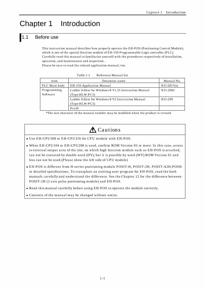
This instruction manual describes how properly operate the EH-POS (Positioning Control Module),which is one of the special function module of EH-150 Programmable Logic controller (PLC).Carefully read this manual to familiarize yourself with the procedures respectively of installation,operation, and maintenance and inspection.Please be sure to read the related application manual, too.
Table 1.1 Reference Manual list
item Document name Manual No.PLC Main body EH-150 Application Manual NJI-281*(x)
Ladder Editor for Windows® V1.25 Instruction Manual(Type:HLW-PC3)
NJI-206C
Ladder Editor for Windows® V2 Instruction Manual(Type:HLW-PC3)
NJI-299
ProgrammingSoftware
Pro-H*The last character of the manual number may be modified when the product is revised.
Cautionsl Use EH-CPU308 or EH-CPU316 for CPU module with EH-POS.
l When EH-CPU104 or EH-CPU208 is used, confirm ROM Version 02 or more. In this case, accessto external output area of the slot, on which high function module such as EH-POS is attached,can not be executed by double word (DY), but it is possible by word (WY).ROM Version 01 andless can not be used.(Please show the left side of CPU module)
l EH-POS is different from H-series positioning module POSIT-H, POSIT-2H, POSIT-A2H,POSHin detailed specifications. To transplant an existing user program for EH-POS, read the bothmanuals carefully and understand the difference. See the Chapter 12 for the difference betweenPOSIT-2H (2 axis pulse positioning module) and EH-POS.
l Read this manual carefully before using EH-POS to operate the module correctly.
l Contents of the manual may be changed without notice.

Capture 1 Introduction
1-2
1.2 Accessories
The following accessories are packed in the EH-POS module. Check each item after unpacking themodule.
No. Item name Model Appearance Numberof pieces
Remark
1 1-axis positioningmodule
EH-POS 1 Caution
l Use EH-CPU308 or EH-
CPU316 for CPU module
with EH-POS.
l When EH-CPU104 or EH-
CPU208 is used, check
ROM Version to be Version02 or more. In this case,
access to external output
area of the slot, can not beexecuted by double word
(DY), but it is possible by
word (WY).
Case:
10320-52F0-008
12 I/O connector
(Cable side)
Connector(Solder type):
20 poles
10120-3000VE
1
Supplied by Sumitomo 3M
CautionEarth the shielded ofconnector and cable to solvenoise problem.
3 Connector forpositioner
TM8DC 1 Supplied by HiroseElectronics
NJI-326:Japanese 14 Instruction manual
NJI-326(X):English 1

Capture 1 Introduction
1-3
1.3 Option
The following options are for the EH-POS module.
No. Name Model (Spec.) Appearance Numberof pieces
Remark
1 Positioner RPS-3A
1st
P O S I T I O N E R
HITACHI
4
2nd
5 6
987
3
FWD REV STOP2 3
1
4
0
1 2
DEL I N S
CLR
MODE
CAN CEL
STR 2nd
CONNECT THE REMOTE CABLE WITHWWITHCONTROLLER AFTER TURNNING OFF THEINPUT POWER OF CONTROLLER
1 This needs another cable forPositioner (Item No.2).
CautionThis is not applied for CEmarking and C-TICK.
EH-POP10 (1m) 12 Cable for positioner
EH-POP28 (2.8m) 1
Only for EH-POS
CautionThis is only for EH-POSpositioner.
EH-POC10 (1m) 1
EH-POC20 (2m) 1
3 Cable for I/Oconnector
EH-POC50 (5m) 1
Supplied by Sumotomo 3M.
Plug:20 pole
10120-6000EL
Case:
10320-3210-000
4 Cable for servo amp (1)HITACHI AD series
(2)YASUKAWA Σ II series
(3)SANYO P series
CautionContact sales office fordetailed information.
Soon on sale

Chapter 2 Features
2-1
Chapter 2 Features1. Build-in continuous automatic operation function
Maximum 256 steps of Automatic operation, Continuous Automatic operation are installed.Step operation, cycle operation, Continuous cycle operation are possible.
2. “Velocity change in Run mode” function. EH-POS realized velocity change in RUN mode, by changing velocity data.
3. S-shaped acceleration functionAt acceleration method, S-shaped acceleration mode (3 steps acceleration mode) is added.At setting of acceleration mode in common parameter, “trapezoid acceleration mode” or “S-shaped
acceleration mode” can be selected.
4. ABS (absolute value) encoder inputEH-POS applies for ABS (absolute value) encoder input.At setting of “Homing mode” in common parameter, you can set homing mode of absolute encoder.(Applied manufacturer/series : Hitachi AD series,YasukawaΣseries/Σ II series, Sanyo Electric P
series)
5. Battery-lessEH-POS applies EEPROM as memory and realizes to back-up memory without battery. It is
rewritable up to about 100,000 times.Preparing for frequent rewriting velocity and position data, a dedicated command is prepared.
6. Easy to use by positionerIf you do not have a programming tool, the positioner can allow you to operate “Homing operation”,
“Manual operation”, “Automatic operation” and “Teaching”. Common parameter setting orautomatic operation data setting is available too.
Positioner can display a position and error code. Positioner is an option.
7. Ease of using position commandEH-POS supports four kinds of position command modes (pulse,µm, inch, degree).
8. Differential Line driver output methodThe differential driver output is added in pulse output method. Both open collector and
differential driver are available on different output terminals.
00step, 01 to 03 step, , FF (255 )Step
Distance, time
Velocity
(Example)
Continuous Cycle Operation
Distance, Time
Velocity Trapezoid acceleration
S - s h a p e d a c c e l e r a t i o n
(Example)
Step
Step
Distance, t ime
Velocity
Before changing velocityA f t e r c h a n g i n g v e l o c i t yR u n m o d e
(Example)

Chapter 3 System configuration
3-1
Chapter 3 System configuration
3.1 Structure and Parts name
Name and function Model EH-POS
Weight Approx. 0.18 kg
Dimension(mm)1) Lock button
2) Reset switch
3)Connector forPositioner
4) I/O connector
5) DIP switch
100
30 95
No Name Function Remarks
1) Lock button This is used when removing the module from the base unit. After it isinstalled to the base unit, the fixation can be reinforced using screws. Inthis case, use M4×10-mm screws.
2) Reset switch When module is abnormal, module is to be reset by pushing this switch.
3) Connector forPositioner
By connecting a positioner, setting and writing of internal data, manualoperation, automatic operation and teaching operations are available.
Positioner is optional.
4) I/O connector This is connector for pulse output and external control input. Connector for cable:SUMITOMO 3M product
Solder type:10120-3000VE
Case:10320-52F0-008
5) DIP switch Setting this switch designates the following operating modes. Even if theswitch setting is changed while the module is energizing, the operatingmode will not be changed. To switch operating modes, turn the poweroff, then do the settings correctly.
Caution
When switch number 5,6 isturned on, external overrunsignal is disable.
ON OFF Supplementary explanationSwitch No 1 2
1, 2 ON ON CW/CCW Pulse Line Output (negative)
ON OFF CW/CCW pulse Line Output (positive)
OFF ON CK/Sign Pulse Line Output (negative)
OFF OFF CK/Sign Pulse Line Output (positive)
3 Not used Not used
4 Ext. COIN disable Ext. COIN enable External permission Operation (When switchnumber 4 is turned off, it is valid.)
5 Ext. +O.RUN disable Ext. +O.RUN enable External CCW overrun Operation (When switchnumber 5 is turned off, it is valid.)
6 Ext. –O.RUN disable Ext. –O.RUN enable External CW overrun Operation (When switchnumber 6 is turned off, it is valid.)

Chapter 3 System configuration
3-2
3.2 System configuration
The system configuration of the EH-150 is shown below.
The EH-150 is a module-type programmable controller with the configuration shown in Figure 3.1.
1) P o w e r m o d u l e
1) P o w e r m o d u l e
2) C P U m o d u l e ( * 1 ) I / O m o d u l e 4 ) B a s i c b a s e
5) E x p a n s i o n u n i t ( o n l y w h e n E H - C P U 2 0 8 / 3 0 8 / 3 1 6 )
6) E x p a n s i o n c a b l e
7) I / O c o n t r o l l e r
3 ) P o s i t i o n i n g m o d u l e ,
I / O m o d u l e
3 ) P o s i t i o n i n g m o d u l e ,
Figure 3.1 EH-150 System configuration diagram
No. Device name Description of function
1) Power module Converts power supply to the power to be used within the EH-150.
2) CPU module*1 Performs operations based on the contents of the user program, receives input andcontrols output.
3) I/O module*2 Positioning module, Input module, output module, analog module
4) Basic base unit*2 Base in which the power module, CPU module, I/O module, etc. are loaded.
5) Expansion baseunit
Base in which the power module, I/O controller, I/O module, etc. are loaded.
6) Expansion cable Cable that connects the I/O controllers for the basic base and expansion base.
7) I/O controller Interface with expansion base and CPU module.
*1 Adopt EH-CPU308 or EH-CPU316 as CPU module with this EH-POS module. If EH-CPU104 or EH-CPU208 isadopted as CPU module, please confirm ROM Version is 02 or more. In this case, access to external output areaof the slot, on which high function module such as EH-POS is attached, can not be executed by double word (DY),but it is possible by word (WY). CPU module of ROM Version01 or less cannot be used with this EH-POSmodule.
*2 The same type unit can be used both for the basic unit and the expansion unit.

Chapter 4 Function and Performance Specifications
4-1
Chapter 4 Function and PerformanceSpecifications
4.1 General Specifications
The general specifications of EH-POS are shown in the table below.
Item Specification
Power requirement 5 V DC, 300 mA, 600 mA (when Positioner connected ) ,(supplied from the programmable controller)
Operating temperature 0 to 55 °C storing temperature –10 to 75 °C)
Operating humidity 20 to 90 % RH (no condensation), storing humidity 10 to 90 % RH (no condensation)
Operating atmosphere No presence of corrosive gases or heavy dusts
Cooling method Natural air cooling
Weight Approx. 0.18 kg
Dimension 30(W) × 100(H) × 95(D) mm (170(D) with I/O Connector)
External power source 5 V DC ±5% 100 mA (for pulse output) , 24 V DC 10 mA/point (for external control input)
100
30 95(60)
(170)
15
Base unit
EH-POSI/Oconnector
Figure 4.1 Dimensions of EH-POS with I/O connector

Chapter 4 Function and Performance Specifications
4-2
4.2 Functional Specifications
The function specifications of EH-POS are shown in the table below.
Item Specification
Number of controlled axes 1 axisMaximum Speed 400k Pulse/sPositioning Number of occupied points 256 points
data Setting method 1. Sequence program2. Positioner (Option)
System 1. Absolute system2. Absolute + Increment system3. Increment system
Positioning command unit 1. Pulse
2. µm3. inch4. degree
Speed command Automatic, manual, homing6.25 to 400k Pulse/s
specification with µm/s, inch/s, degree/sSpeed stage 10 stages
Acceleration and deceleration Linear acceleration and decelerationS-shaped acceleration and deceleration (3 stage acceleration and Deceleration)
Acc./dec. time 1 to 65,535 ms
Backlash correction 0 to 255 pulses
Range +2,147,463,647 to –2,147,463,648 pulses
Pulse Output form 1. Pulse train (CW/CCW)
2. Clock + direction signal (CK/Sign)
DIP switch No.1 & No.2 decide (Output form and logic polarity).
Positioningsystem
Pulse Output method 1. Open collector Output (Photo coupler isolation)
2. Differential driver Output (Photo coupler isolation)Function of homing 1. Desirable homing
2. Low speed homing3. High speed homing (Limit SW OFF edge)4. High speed homing (Z or C Pulse input)
Absolute encoder AD series of HITACHI, Σ/Σ II of YASUKAWA and P series ofSANYO are available.
Teaching AvailableManual (JOG) operation Pulse output by manual input
I/O assignment Word 4W/4W
Operation of EH-POS in the CPU’s stop Enable by I/O set or a Positioner (Option)
Caution 1.Positioner is not applied for CE marking and C-TICK.2.When the CPU is stopped in the running, the motor goes slow down and stop.3.Maximum moving distance is 2,147,463,647 pulses in one operation. In case of the over maximum moving distance,
the motion is stopped at the maximum moving value.4.When a power supply of EH-150 is turned off during a power supply of servo system is on, EH-POS may output some
pulses. So, please turn off the power supply of the servo system, before turning off the power supply of EH-150. Andmake homing operation after power supply is turned on in case of position control mode.

Chapter 4 Function and Performance Specifications
4-3
4.3 I/O Interface Specifications
I/O interface specifications of EH-POS are shown in the table below.
Items Specification
CW/CCW Pulse line Output
CK/Sign Pulse line Output
Opto-isolated open collector transistor (max.30 V DC,
30 mA Resistor Load)
Opto-isolated line driver output (5 V DC)
Max. leak current 100 µA or less
Output
Max. ON drop voltage 0.8 V (at output current = 30mA)
Input voltage 10.8 to 30 V DC
Input Impedance Approx. 2.2 kΩ
Input current Approx. 10 mA(24 V DC)
Min. ON voltage 9 VOperatingVoltage Max. OFF voltage 3.6 V
ON to OFF 1 ms or lessInput delay
OFF to ON 1 ms or less
Polarity Only input of encoder signal is Plus common, others none
Input
Isolation method By photo-coupler

Chapter 4 Function and Performance Specifications
4-4
1) Positioner connector (CN1): Base on RS-422
Terminal configuration Diagram of internal circuit
No. Sign signal name
1) Do− Driver output −
2) Do+ Driver output +
3) Ri− Receiver input −
4) Ri+ Receiver input +
5) 5 V DC+ +5V
6) 0 V GND
7) 0 V GND
8) 12 V DC− −12V
2) I/O connector (CN2)
Terminal configuration Diagram of internal circuit
No. Sign signal name
1) 5 V DC+
2) P5G
Eternal power
Source(pulse output)
3) CW
4) CCW
Open collector
pulse output
5) CW+
6) CW−
7) CCW+
8) CCW −
Differential
pulse output
9) C+
10) C−
Encoder
C-phase
11) PS−
12) PS+
Encoderposition signal
13) COIN Operation complete
14) PROG Home LS
15) +O.RUN +Over Run
16) −O.RUN −Over Run
17) MODE-SEL
Control mode Switch
18) M-CW Manual CW
19) M-CCW Manual CCW
20) 24 V DC+ External powersource (control)
8 )
1 )C N 1
1
8
..
.
...
5V
GND
-12V
GND
5V
1)2)
4)
3)
5)
8)
7)
6)
Internalcircuit
Position
er
CN2
10
11
20
1
10)
1)
20)
11)
.
.
.
.
.
.
.
.
.
.
.
.
10),12)
9),11)
13)to 19)
20)
2)
1)
3),4)
5),7)
InternalCircuit
5V
5V
6),8)

Chapter 4 Function and Performance Specifications
4-5
4.4 Input/output Signal
Input /output signals of EH-POS are shown in the table below.
No. I/O Symbol Signal name Content
1) P5V
2)
Power
P5G
Power for Pulse output Power supply terminal
3) CW
4) CCW
Open collector output (Note 1)
5) CW+
6) CW−
7) CCW+
8)
Output
CCW −
Signal for Pulse output
Differential driver output( Note 1)
9) C+
10) C−
C phase of encoder (or Z phase) High-speed homing 2
(C or Z phase of servo driver)
11) PS−
12) PS+
Encoder position Data input signal when absolute valueencoder is used
13) COIN Operation permission Read deviation 0 of servo driver(Note 2)
14) PROG Home limit switch Home/datum LS
15) +O.RUN CCW overrun (Normally ON) CCW direction overrun(Note 2)
16) −O.RUN CW overrun (Normally ON) CW direction overrun(Note 2)
17) MODE-SEL Control mode select When the system is in the velocity +positioning control mode, change the
mode to positioning mode by turning theswitch from ON to OFF.
18) M-CW CW Manual operation Input of CW direction operation in themanual operation mode
19)
Input
M-CCW CCW Manual operation Input of CCW direction operation in themanual operation mode
20) Power COM(+24V) External power source External power source common terminal
Note 1: The pulse output method (CW/CCW or CK/direction change) and output logic (Positive/negative) are set byDIP switch 1 and 2. DIP switch 3 is not used.
Note 2: When the external inputs (COIN, +O.RUN, −O.RUN) are not used, the output input is made invalid bysetting the DIP switch 4,5,6 ON. Please note the module read the setting of DIPswitch when power on. Whenyou wish the external inputs (COIN, +O.RUN, −O.RUN) valid, set DIPswitch 4,5,6 OFF definitely.
ON
1 2 3 4 5 6
In case of Clock/directionsignal( positive)
It is possible to set invalidof external signal ofCOIN ,+O.RUN,−O.RUNby setting Dip Switch4,5,6.

Chapter 4 Function and Performance Specifications
4-6
4.5 Output Method
Pulse output method (CW/CCW or, CK/direction change) or, output logic (positive/negative) is set by the DIPswitch No.1, 2 at side of module. Set the same method of the pulse output of EH-POS and that of servo controller.
DIP_SWNo.
Output methodApparatus of DIP_SW
1 2
ON ON (1) CW/CCW pulse output (negative logic)
ON OFF (2) CW/CCW pulse output (positive logic)
OFF ON (3)Clock/direction signal output(negative logic)
ON
(4)Clock/direction(positive logic)(Factory setting)
1 2 3 4 5 6
OFF OFF (4)Clock/direction signal output(positive logic)
Output method Output signal Forward(CCW direction) Reverse(CW direction)
(1) CW/CCW Pulse output(Negative logic)
CW
CCW
(2) CW/CCW Pulse output(Positive logic)
CW
CCW
(3) Clock/direction(Negative logic) Clock
(CW)
Direction signal
(CCW)
“L” “H”
(4) Clock/direction(Positive logic) Clock
(CW)
Direction signal
(CCW)
“H” “L”

Chapter 4 Function and Performance Specifications
4-7
4.6 Name of LED
LEDs on the front part of EH-POS module are explained in the table below.
LED part of EH-POS LEDname
Signal name Content Color
POW Power Lighted when module is normal Yellow green
RUN Run Positioning ( Pulse are outputting) Yellow green
STB Stand by Input queuing (Pulses not working) Yellow green
O.R Over run Lighted at overrun Red
CMDE Command error Lighted at command error Red
WDE Watch dog timererror
Lighted at Micro computer error Red
(Note) “WDE” lights a moment, when power is made ON/OFF. This is not abnormal.
POSITIONING
WDEPOW
EH-POS
RUN STB O.R CMDE
Chapter 5 Trial Run(Simple Operation Example)
5-1
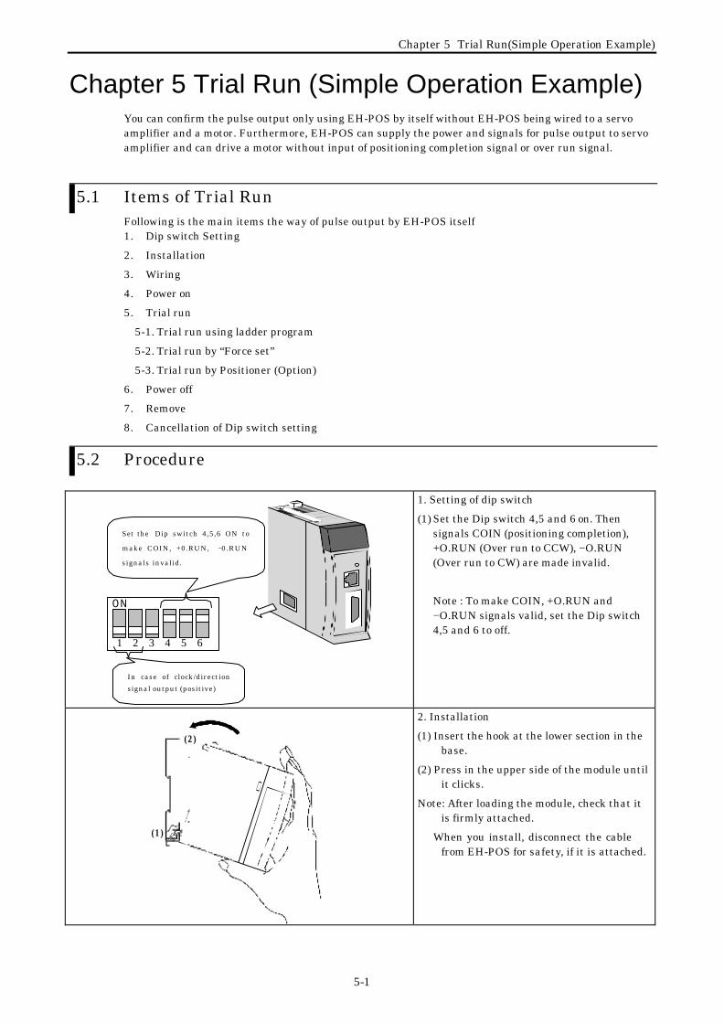
Chapter 5 Trial Run (Simple Operation Example)You can confirm the pulse output only using EH-POS by itself without EH-POS being wired to a servoamplifier and a motor. Furthermore, EH-POS can supply the power and signals for pulse output to servoamplifier and can drive a motor without input of positioning completion signal or over run signal.
5.1 Items of Trial RunFollowing is the main items the way of pulse output by EH-POS itself1. Dip switch Setting
2. Installation
3. Wiring
4. Power on
5. Trial run
5-1. Trial run using ladder program
5-2. Trial run by “Force set”
5-3. Trial run by Positioner (Option)
6. Power off
7. Remove
8. Cancellation of Dip switch setting
5.2 Procedure
ON
1 2 3 4 5 6
In case of clock/direction
signal output (positive)
Set the Dip switch 4,5,6 ON to
make COIN, +0.RUN, −0.RUN
signals invalid.
1. Setting of dip switch
(1) Set the Dip switch 4,5 and 6 on. Thensignals COIN (positioning completion),+O.RUN (Over run to CCW), −O.RUN(Over run to CW) are made invalid.
Note : To make COIN, +O.RUN and−O.RUN signals valid, set the Dip switch4,5 and 6 to off.
(2)
(1)
2. Installation
(1) Insert the hook at the lower section in thebase.
(2) Press in the upper side of the module untilit clicks.
Note: After loading the module, check that itis firmly attached.
When you install, disconnect the cablefrom EH-POS for safety, if it is attached.

Chapter 5 Trial Run(Simple Operation Example)
5-2
0 14 58 91 2 1 3
P O R T1
P O R T2
EH-150HITACHI
POWER
CircuitBraker orEarth leakageBraker
100 V AC
to 200 V AC
NoiseFilter
IsolationTransformer
3. Wiring to power supply module.
(1) Use a power line cable over 2mm squarenot to drop the voltage.
(2) Use an earth cable (to FE terminal) morethan 2 mm square. The impedanceshould be less than 100 ohms.The earth cable should be less than 20 m.
(2-1)Common use with instrumentationcabinet or relay cabinet ispermitted.
(2-2)Do not share with the earth line ofequipment such as high frequencyheating furnace, large-scale powercabinet (more than 5kW), thyristorconverter, electric welding machine,which may emit noise.
(2-3)Use a noise filter certainly in powersupply line.
(3) The terminal screw is M3. Tighten ascrew with torque of 49 to 78 N·m.
(4) Use a same power supply for bothmodules in basic and expansion rack.
4. Power on
Switch on the circuit breaker.
Set I/O assignment of EH-POS as “word 4W/4W” at configuration setting on programming tool.Please refer to the manual of programming software about ladder programming.Following description is the case that EH-POS is put on slot 0.
WY4=H0300
R100=1
R7E3
TD10R100
TD10
0.1S 50
WY4=H0700
END
1)
2)
3)
5. Trial run5-1 Trial run using ladder program
(1) Make the ladder program as left anddownload to the CPU.
[ Program ]1) During the 1st scan after RUN, the
“Continuous pulses for forward rotation ofmanual operation command” is executed.RUN LED (Green) lights up. R100 is set to 1.
2) When R100 is on, the timer TD10 willstart, and the current value increases.
3) After 5 seconds, TD10 turns to on, andH0700 is set in WY4. Then “Slow down andstop command” is executed. The RUNLED (Green) will switch off and STB LED(Green) will light up.
P O W W D E
E H - P O S
R U N S T B O . R C M D E
P O S I T I O N I N G
L i g h tO F F
(2) Make the RUN-switch on to run EH-CPU. Then RUN LED on EH-POS will light up for 5 seconds. Pulses are output during the time. After 5 second, RUN LED turns off and STB LED lights on.

Chapter 5 Trial Run(Simple Operation Example)
5-3
Concerning how to use the ladder editor, please refer to the manual of Ladder Editor.Following is a description for using Ladder Editor for Windows (Type: HLW-PC3).
5-2 Test operation by Forced Set/Reset(1) Start Ladder Editor and select Online
mode.Make sure I/O assignment of EH-POS is
“Word 4W/4W”. For details, refer LadderEditor manual Type HLW-PC3.
(2)Switch the mode by choosing the from[Edit-Readout ] to [Online]-[Mode]-[Monitor] on the Ladder Editor.
(3) Select [Forced Set/Reset] in the menu bar.Then the dialog box is displayed.
(4) Input ”WY0004” at I/O No. (“WY4” is alsoaccepted) and “0300” as hexadecimal setvalue. Then click the [Execute] button.“Forward rotation of manual operation bycontinuous pulses command (H300)” isexecuted.
POW WDE
EH-POS
RUN STB O.R CMDE
POSITIONING
(5) After completion of step 4), the RUN LED(Green) will light up and pulses will beoutput from EH-POS.
(6) Input ”WY0004” (“WY4” is alsoacceptable) as the I/O No., and “0700”(“700” is also acceptable) as Hexadecimalset value. Then click the [Execute] button.“Stop with slowdown” command is executed.
(7) After completion of step 6), the RUN LED(Green) will turn off and STB LED (Green)will light up.

Chapter 5 Trial Run(Simple Operation Example)
5-4
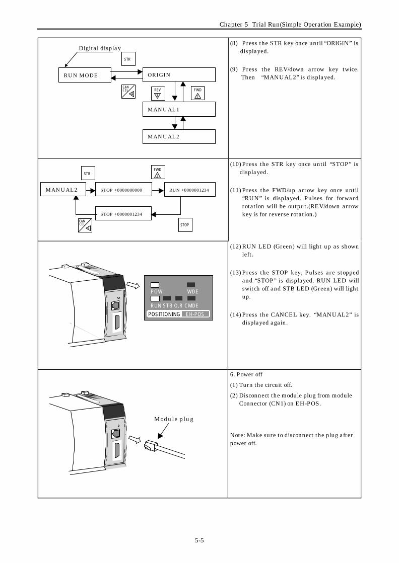
5-3. Trial run using the positioner (Option)
(1) Connect cable for positioner to theconnector behind the positioner.
Module plug
(2) Turn the circuit off.
(3) Connect the module plug to moduleConnector (CN1) of EH-POS until itclicks.
(4) Turn the circuit on.
Note: Make sure to connect the plug (cable)before power on.
(5) “MONITOR MODE” is displayed after“POWER ON” signal.
(6) Press the “2nd/1st” key. 2nd LED willlight up and 2nd keys are available.
(7) Press the MODE key twice until ”RUNMODE” is displayed.
CANCEL/left arrow key
Digital display
2nd/1st key
MODE/right arrow key
STR key
REV/down arrow keyFWD/up arrow key
2nd LED
Positioner
Cablefor positioner(Roundconnector)
Chapter 5 Trial Run(Simple Operation Example)
5-5
(8) Press the STR key once until “ORIGIN” isdisplayed.
(9) Press the REV/down arrow key twice.Then “MANUAL2” is displayed.
(10) Press the STR key once until “STOP” isdisplayed.
(11) Press the FWD/up arrow key once until“RUN” is displayed. Pulses for forwardrotation will be output.(REV/down arrowkey is for reverse rotation.)
POW WDE
EH-POS
RUN STB O.R CMDE
POSITIONING
(12) RUN LED (Green) will light up as shownleft.
(13) Press the STOP key. Pulses are stoppedand “STOP” is displayed. RUN LED willswitch off and STB LED (Green) will lightup.
(14) Press the CANCEL key. “MANUAL2” isdisplayed again.
Module plug
6. Power off
(1) Turn the circuit off.
(2) Disconnect the module plug from moduleConnector (CN1) on EH-POS.
Note: Make sure to disconnect the plug afterpower off.
RUN MODE ORIGIN
MANUAL1
FWD
2
REV3
CELCAN
4
STR
MANUAL2
STOP +0000000000
CELCAN
4STOP
STOP +0000001234
RUN +0000001234MANUAL2
Digital display
STRFWD
2

Chapter 5 Trial Run(Simple Operation Example)
5-6
(2)
(1) (3) 7. Removing
(1) Push in the lock button.
(2) With the lock button pushed in, pull thetop of the module toward the front.
(3) Raise it toward the front.
ON
1 2 3 4 5 6
Set the Dip switch 4,5,6 to off
8. Cancellation of the dip switch
(1) Set the DIPswitch 4,5,6 to off.External signals to COIN (positioningcompletion), +O.RUN (Over run to CCW),–O.RUN (Over run to CW) are valid.
Chapter 6 Operation Data Setting
6-1
Chapter 6 Operation Data Setting
6.1 Operation DataIn order to operate the EH-POS, common parameters as well as automatic operation position data foreach step are required to be set.Common parameters and 0 step of automatic operation position data are set with default values.
6.1.1 Common parameterThe common parameter consists of 12 data (15-words) and is needed for all operation modes (homing
mode, manual operation, and automatic operation). Set the data correctly before operation.Default values are set as follows.
Most significant bit ←(MSB)
→ Least significant bit(LSB)
Para
met
er N
o.
Com
mun
icatio
n w
ord
No.
15 14 13 12 11 10 9 8 7 6 5 4 3 2 1 0
Content
Defaultvalue
Hexadecimal(Decimal)
1 1(a)Homing
mode(b)Velocity
mode
(c)Acceleration/Deceleration mode
(d )
Position
specifying
unit 1
(e)
Position
specifying
unit 2
Homing modeVelocity mode,
Acceleration/Deceleration modePosition specifying unit
H0000(0000)
2 2Pulse number for one rotation
((e)Valid for position control unit is µm, inch, degree)Pulse number for one rotation of
motor 1 to 65535(HFFFF)H07D0(2000)
3 3Work move length for one rotation
((e)Valid for position control unit is µm, inch, degree)
Work move length at one rotationof motor 1 to 65535(HFFFF)
H07D0(2000)
4 4 Upper limit of speedSetting the upper limit speed of
the velocity control mode1 to 65535(HFFFF)
H1F40(8000)
5 5 Initial speedSetting of initial speed of manual
operation/automatic operation1 to 65535(HFFFF)
H0010(0016)
6 6 Manual /High-speed homing velocitySetting the velocity in the manual
operation/ High-speed homing1 to 65535(HFFFF)
H0020(0032)
7 7 Low-speed homing velocitySetting the velocity in the low-
speed homing1 to 65535(HFFFF)
H0010(0016)
8 8 Acceleration/Deceleration time
Setting Acceleration /Decelerationtime in the homing/manualoperation (unit: ms) 1 to
65535(HFFFF)
H03E8(1000)
9 9 BacklashSetting the backlash correcting
data1 to 65535(HFFFF)
H0000
10 Upper limit position data (Lower)
1011 Upper limit position data (Upper)
Setting the maximum positiondata for normal rotation direction
+2,147,483,647(H7FFFFFFF)to –2,147,483,648(H80000000)
H3FFFFFFF(+1073741823
)
12 Lower limit position data (Lower)
1113 Lower limit position data (Upper)
Setting the maximum positiondata for reverse rotation direction
+2,147,483,647(H7FFFFFFF)to –2,147,483,648(H80000000)
HC0000000(–
1073741824)
14 Home position data (Lower)12
15 Home position data (Higher)
Setting the position data of thestarting point
+2,147,483,647(H7FFFFFFF)to –2,147,483,648(H80000000)
H00000000

Chapter 6 Operation Data Setting
6-2
Note 1 The maximum position value in one operation is 2,147,483,647 (H7FFFFFFF) pulses.Note 2 In case to return to default value, execute the command (H4D00) to set the default. See the 6.3.2
Communication Command in detail.Note 3 At homing operation or manual operation including teaching operation, the system can be operated by
setting the common parameters only.Note 4 When data is set over the range of 2,147,483,647 (H7FFFFFFF) to −2,147,483,648(H80000000),
H00000000 is set automatically for the position data of parameter No.10, 11 and 12.Note 5 Because the common parameters and automatic operation position data are stored in EEPROM, data
will not be lost at power failure. EEPROM can be rewritten up to about 100,000 times.
Common parameter default values
Default valueParameterNo.
Hexadecimal DecimalContent
0 (b15~b12) 0 (b11~b8) 0 (b7~b4) 0 (b3~b0)
1
H0000 −
Desirablehoming
Velocitymagnification6.25
TrapezoidalAcc./Dec.
Pulsemagnification ×1
2H07D0 2000 Pulse number at one rotation of motor = 2,000 pulse
(Position control setting is pulse in parameter No.1, this data is not valid. Whenthe setting is except for pulse, this value is valid.)
3H07D0 2000 Work move length at one rotation of motor = 2, 000 pulse
(Position control setting is pulse in parameter No.1, therefore this data is notvalid. When the setting is except for pulse, this value is valid.)
4H1F40 8000 Upper limit of speed of speed control mode
= 8,000×6.25(speed magnification of parameter No.1) ×1(Magnification ofparameter No.1)= 50,000 pulse/s
5H0010 16 Setting of initial speed of manual operation/automatic operation
= 16×6.25(speed magnification of parameter No.1) ×1(Magnification ofparameter No.1) = 100 pulse/s
6H0020 32 the velocity in the manual operation/ High-speed homing
= 32×6.25(speed magnification of parameter No.1) ×1(Magnification ofparameter No.1) = 200 pulse/s
7H0010 16 the velocity in the low-speed homing
= 16×6.25(speed magnification of parameter No.1) ×1(Magnification ofparameter No.1) = 100 pulse/s
8H03E8 1000 Acceleration /Deceleration time in the homing/manual operation (unit: ms) =
1,000 ms.
9H0000 0
Backlash correcting data = 0 pulse
10H3FFFFFFF +1,073,741,823 The maximum position data for normal rotation direction = +1,073,741,823
(H3FFFFFFF)
11HC0000000 –1,073,741,824 The maximum position data for reverse rotational direction = –1,073,741,824
(HC0000000)
12H00000000 0
Position data of the home position = 0
Chapter 6 Operation Data Setting
6-3
(1) Common parameter No.1
b15 b 14 b 13 b 12 b 11 b 10 b 9 b 8 b 7 b 6 b 5 b 4 b 3 b 2 b 1 b 0
0 0 0 0
(a) (b) (c) (d) (e)
(a) Homing mode (b15 to b 12) Bits in the table below set homing modes.
Data (Hexadecimal)b15 b14 b13 b12 Homing Mode
b15=0(Reverse) b5=1(Forward)0 0 0 0 Desirable homing H0*** –* 0 0 1 Low speed homing H1*** (CW) H9*** (CCW)* 0 1 0 High speed homing 1 (off edge) H2*** (CW) HA*** (CCW)* 0 1 1 High speed homing 2 (marker end) H3*** (CW) HB***CCW)0 1 0 0 Σ series 12bit ABS encoder H4*** –0 1 0 1 ΣII series 16bit ABS
encoderH5*** –
YASUKAWA*1
ΣII series 17bit ABSencoder
0 1 1 0HITACHI AD series17bit ABS
encoder
H6*** –
0 1 1 1
ABSEncoderHoming
SANYO P series H7*** – *: Optional value *1: Not applied to 15bit ABS Encoder CW/CCW shows rotating direction.(b) Velocity mode(b11 to b 8)
Bits in the table below set velocity range and velocity magnification.b11 b10 b9 b8 Velocity magnification Velocity range Data
(Hexadecimal)0 0 0 0 6.25 50k pulse/s H*0**
0 0 0 1 12.5 100k pulse/s H*1**
0 0 1 0 25 200k pulse/s H*2**
0 0 1 1 50 400k pulse/s H*3**
*: Optional value(c) Acceleration/Deceleration mode(b7 to b 4)
Acceleration/Deceleration mode set by bits in the table below.b7 b6 b5 b4 Acc./Dec. mode Content Data
(Hexadecimal)0 0 0 0 Trapezoidal Acc./Dec.mode H**0*
0 0 0 1 S-Shaped Acc./Dec.mode1 S-Shaped Acc./Dec. standard H**1*
0 0 1 0 S-Shaped Acc./Dec. mode2 Up/down edge is smooth thanS-Shaped Acc./Dec. standard
H**2*
0 0 1 1 S-Shaped Acc./Dec. mode3 Close to Trapezoid than S-ShapedAcc./Dec. standard
H**3*
*: Optional value Explanation of Acceleration/Deceleration mode

Chapter 6 Operation Data Setting
6-4
S-Shaped Acc/Dec 3:dot line
Trapezoidal
S-Shaped Acc/Dec 1(Std.):solid line
S-Shaped Acc/Dec 2:chain line
Acceleration time A
Velocity
Deceleration time BA/3 A/3 A/3
time
Acc/Dec
B/3 B/3 B/3

Chapter 6 Operation Data Setting
6-5
(d) Position control magnification (b3, b2)
Position control magnification is to be set.b3 b2 Magnification
0 0 10 1 101 0 1001 1 1,000
(Note) In case position control unit is pulse, magnification is always 1.
(e) Position control unit (b1, b0)
Position control unit is to be set.b1 b0 Unit Range To data 10 0 pulse +2,147,483,647 to –2,147,483,648 10 1 µm +214,748,364.7 to –214,748,364.8µm 0.1 µm1 0 inch +21,474.83647 to –21,474.83648 inch 0.00001 inch1 1 degree +21,474.83647 to –21,474.83648 degree 0.00001 degree
Control position setting ((d), (e)) *: Optional valueb3 b2 b1 b0 Magnification Unit Data
(Hexadecimal)
0 0 0 0 pulse H***00 0 0 1 µm H***10 0 1 0 inch H***20 0 1 1
1
degree H***30 1 0 1 µm H***50 1 1 0 inch H***60 1 1 1
10
degree H***71 0 0 1 µm H***91 0 1 0 inch H***A1 0 1 1
100
degree H***B1 1 0 1 µm H***D1 1 1 0 inch H***E1 1 1 1
1,000
degree H***F
<Position control magnification and unit>
Positioning module controls the position and velocity by number of pulses. Therefore moving distancemust be converted to various units (µm, inch, degree) to number of pulses. The converting expression is asfollows:Moving amount for a pulse(Lp) Lp = moving amount a rotation / pulse number a rotation
Setting of moving distance for a rotation, in case of µm it is 0 to 6553.5µm, in case of inch it is 0 to 0.65535inch, in case of degree it is 0 to 0.65535 degree, therefore necessary moving distance for a rotation islacked. In this case, set the proper position control magnification ((d)). Moving amount a rotation (real moving distance) = Moving distance a rotation (parameter No.3) × magnification (parameter No.1 (d) position
control b 3,b2)
In this case, moving distance for a pulse (Lp) Lp = moving amount a rotation × magnification / number of pulses a rotation

Chapter 6 Operation Data Setting
6-6
Examples of Position Specification Unit
Example 1 Example 2 Example 3 Example 4Item
Specified by pulse Specified by µm Specified by inch Specified by Degree
Contents Making a singleCCW turn by themotor which moveswith 16384 pulseper rotation
Moving a work 0.1m(100,000µm) , by themotor which moves with16384 pulse per rotation
Moving a work4inchs , by the motorwhich moves with16384 pulse perrotation
Moving a work 360degree , by the motorwhich moves with16384 pulse perrotation
Motoroperation
Common parameter and automatic operation position data in example
Example 1 Example 2 Example 3 Example 4
Data
No. item
Specified by pulse Specified by µm Specified by inch Specified by degree
H0000 H0009 H0006 H030F
1
Homing modeVelocity coef.Acc./Dec.modePosition spec.
Desirable homingVelocity magnification 6.25Trapezoidal Acc./Dec.Pulse spec, mag.1
Desirable homingVelocity magnification6.25Trapezoidal Acc./Dec.Mm spec mag.100
Desirable homingVelocity magnification 6.25Trapezoidal Acc./Dec.inch spec, mag.10
Desirable homingVelocity magnification 50Trapezoidal Acc./Dec.degree spec, mag.1000
D **** (Note1) D16384 D16384 D163842
Pulse perrotation If position spec. is pulse,
setting data is invalid.16384 Pulse per rotation 16384 Pulse per rotation 16384 Pulse per rotation
D**** (Note1) D10000 D40000 D36000
3
Workmovementper Rotation
If position spec. is pulse,setting data is invalid.
10,000×0.1×100= 100,000µm⁄rotation
40,000×0.00001×10= 4 inch⁄rotation
36,000×0.00001×1000= 360 degree⁄rotation
D8000 D8000 D8000 D14400
4Velocityupper limit 8,000 × 6.25
= 50k pulse/s
8,000 × 0.1 × 6.25
= 5,000 µm/s
8,000 × 0.00001 × 6.25
= 0.5 inch/s
14,400 × 0.00001 × 50
= 7.2 degree/s
D0016 D1000 D0400 D4000
5Initialvelocity
16 × 6.25
= 100 pulse/s
1,000 × 0.1 × 6.25
= 625 /µm s
400 × 0.00001 × 6.25
= 0.025 inch/s
4,000 × 0.00001 × 50
= 2 degree/s
D0032 D2000 D0800 D8000
6
Manual/Highspeed homingvelocity
32 × 6.25
= 200 pulse/s
2,000 × 0.1 × 6.25
= 1,250 /µm s
800 × 0.00001 × 6.25
= 0.05 inch/s
8,000 × 0.00001 × 50
= 4 degree/s
D0016 D1000 D0400 D4000
7
Low speedhomingvelocity
16 × 6.25
= 100 pulse/s
1,000 × 0.1 × 6.25
= 625 /µm s
400 × 0.00001 × 6.25
= 0.025 inch/s
4,000 × 0.00001 × 50
= 2 degree/s
D1000 D1000 D1000 D10008 Acc./Dec. time
1,000 ms 1,000 ms 1,000 ms 1,000 ms
9 Backlash 0 0 0 0
10Upperposition data
H3FFFFFF H3FFFFFF H3FFFFFF H3FFFFFF
11Lowerposition data
HC0000000 HC0000000 HC0000000 HC0000000
Com
mon
Param
eter
12Homeposition data
0 0 0 0
Note1: “*” is an optional value.Note2: Constant 0.1 and 0.00001 used in calculations are magnification of conversion of one pulse. (Refer to clause e of common parameter No.1.)
16384 pulse/rotation Work0.1 m
(100,000µm) 4 inch Work360 degree
Motor MotorMotor
Motor
Work

Chapter 6 Operation Data Setting
6-7
Example1 Example2 Example3 Example4
Data No item
Specified by pulse Specified by µm Specified by inch Specified by DegreeH8000 H8000 H8000 H8000
1Operationmode/Dwell
Operation valid.
No continuous operation.
Position control, ABS mode,
Dwell 0
Operation valid.
No continuous operation.
Position control, ABS mode,
Dwell 0
Operation valid.
No continuous operation.
Position control, ABS mode,
Dwell 0
Operation valid.
No continuous operation.
Position control, ABS mode,
Dwell 0
D1000 D1000 D1000 D10002
Accelerationtime 1,000 ms 1,000 ms 1,000 ms 1,000 ms
D1000 D1000 D1000 D1000
3Deceleration
time 1,000 ms 1,000 ms 1,000 ms 1,000 ms
D0052 D3200 D1280 D14400
4 Velocity 52 × 6.25
= 325 pulse/s
3,200 × 0.1 × 6.25
= 2,000 µm/s
1,280 × 0.00001 × 6.25
= 0.08 inch/s
14,400 × 0.00001 × 50
= 7.2 degree/s
D16384 D1000000 D400000 D36000000
Auto. O
pe. Pos. D
ata
5Targetposition data 16,384 pulse
1000,000 × 0.1
= 100,000 µm
400,000 × 0.00001
= 4 inch
36,000,000 × 0.00001
= 360 degree
Chapter 6 Operation Data Setting
6-8
(2) Common parameter No.4 to 7
Calculation of Velocity data VD in Common parameter No.4 to7 is explained here. Range of the data is1 to 65535(HFFFF). Velocity data (V) is calculated on the product of the velocity data (VD) set in Common parameter No.4to7 and the Velocity magnification in Common parameter No.1 (b).
V=VD × KV V: Velocity (Output frequency)[pulse/s] VD: Speed data (Common parameter No.4 to 7)[pulse/s] KV: Velocity magnification(b11 to b8: H* ** in Common parameter No. 1)
<Example> When the velocity (V) should be 10,000pulse/s, the setting of speed data (VD) is calculated as follows..
1) In case b11 to b8 in Common parameter No. 1 is “0” (H*0**): KV =6.25 VD = V/ KV = 10,000/6.25 = 1,600 = D1600 (H0640)
2) In case b11 to b8 in Common parameter No. 1 is “1”(H*1**):KV=12.5 VD = V/ KV = 10,000/12.5 = 800 = D0800 (H0320)
3) In case b11 to b8 in Common parameter No. 1 is “2”(H*2**):KV=25 VD = V/ KV = 10,000/25 = 400 = D0400 (H0190)
4) In case b11 to b8 in Common parameter No. 1 is “3”(H*3**):KV=50 VD = V/ KV = 10,000/50 = 200 = D0200 (H00C8)
When the velocity (V) should be Maximum speed (400k pulse/s),the setting of speed data (VD) is calculatedas follows.
V= V/ KV = 400,000/50 = D8000 (H1F40)
(3) Common parameter No.8This parameter sets the acceleration or deceleration time data. Time unit is ms and it is set in the rangeof 1 to 65,535 ms (1 to 65535(HFFFF)).
Explanation of Initial speed/Operation speed/Acc. time/Dec. time
Velocity
Acc time
Time(distance)
Dec time
V (Operation speed)
V0 (Initial speed)
Note: If a difference between initial speed and running speed is big, a controlled motor might not stop withindeceleration time. In this case, please adjust the speed by setting the initial speed or velocity mode(velocity coefficient) of common parameter No.1 (b) to rather higher.

Chapter 6 Operation Data Setting
6-9
(4) Common parameter No.9
This parameter sets the backlash amount. The setting range is 1 to 65535(HFFFF).
(Backlash correction procedure)Correction of backlash is performed every time when the direction of rotation of the mother is changed inthe manual operation (including teaching operation) and automatic operation modes.In addition note that the display of the current position changes in the homing mode.
(a) Automatic operation absolute modeWhen the object is to be moved from point A to point B, the current position after moving to point B is thedata of point b + the backlash amount (low-speed homing, high speed homing2), or the data of point B(high-speed homing 1) if A < B.To the contrary, if A > B, the current position after moving to point B is the data of point B (low-speedhoming, high-speed homing 2) or the data of point B – backlash amount (high-speed homing 1)
Homing modeCurrent position
displayHoming mode
Current positiondisplay
Low-speed homing B + Backlash amount Low-speed homing B
High-speed homing 1(Note 1)
BHigh-speed homing 1(Note 1)
B - Backlash amount
High-speed homing 2 B + Backlash amount High-speed homing 2 B
(a) In case of A<B (b) In case of A>B
The current position of point A displayed is also changed depending on the positional direction.
(Note 1) When ON period of the starting point LS is short (refer Caution in 8.1.3), the value of (a)
and (b) will be reversed.
(Note 2) The backlash correction is not guaranteed when an optional starting point is set.
CWdirection
CCWdirection
A B
CCWdirection
CWdirection
AB

Chapter 6 Operation Data Setting
6-10
(1) When the homing mode is set to low-speed homing, and positioning from point A to point B isperformed by the automatic operation using the following data,
Point A position : 1,000(Current position display)Point B position : 3,000(Target position data)Backlash amount : 50
(2) When the homing mode is set to high-speed homing1, and positioning from point A to point B isperformed by the automatic operation using the following data,Point A position : 3,000(current position display)Point B position : 1,000(Target position data)Backlash amount : 50
Example (In case of the automatic Operation Absolute Mode)
CCWdirection
A B
CWdirection
Number of pulsed generated: 2,050 pulses
Current position: 1,000 (Target position: 3,000) Current position: 3,050
Compensated by the backlash offset
AB
Number of pulsed generated: 2,050 pulses
Current position: 3,000(Target position: 1,000) Current position: 950
Compensated by the backlash offset

Chapter 6 Operation Data Setting
6-11
(b) In case of the automatic operation increment modeThe pulses added by the backlash amount is output every time when the positioning direction is changed.Namely, If the previous positioning direction is CW, and the current direction is CCW, the number ofpulses increased by the backlash amount is generated in CCW direction.To the contrary, if the previous moving direction is CCW, and current direction is CW, the number ofpulses increased by the backlash amount is generated in CW direction. If the moving directions are thesame, no backlash amount is corrected.
(1) When the moving direction is changed from CCW to CW directionTarget position data: -1,000Backlash amount: 50
(2) When the moving direction is changed from CW to CCW directionTarget position data: 1,000Backlash amount: 50
Example (In case of the automatic operation increment mode)
CCWdirection
CWdirection
Number of pulses generated: 1,050 pulses
Target position: -1,000(HFFFFFC18)Current position: -1,050(HFFFFFBE6)
Previous moving direction
CCWdirection
CWdirection
Number of pulses generated: 1,050 pulses
Target position: 1,000Current position: 1,050
Previous moving direction

Chapter 6 Operation Data Setting
6-12
(c) In case of the manual operationThe pulses added with the backlash amount are output when the moving direction is changed. In case ofinching operation (moving by one pulse), the backlash amount + one pulse are output.
Backlash amount: 50When the system is stopped at position 1,000 by CCW input and moved by inching operation by CWinput.
Make sure to stop in the direction of homing and set the data of the target position at teaching modeusing backlash compensation.
Homing mode Stopping direction
Low-speed homing CW direction
High-speed homing 1 CCW direction
High-speed homing 2 CW direction
Example (Manual Operation)
CCW Input
CW InputInching
CCWdirection
CWdirection
Indication of Current position: 1,000
Number of pulses generated: 51 pulses
Indication of Current position 949
(after Inching)
Cautions required in teaching operation

Chapter 6 Operation Data Setting
6-13
(5) Common parameter No.10
This parameter sets the upper limit of the position data. The default data is1,073,741,823(H3FFFFFFF).The available range is between +2,147,483,647(H7FFFFFFF) and −2,147,483,648(H80000000).If an attempt to move the system in the CCW direction with a target positional data greater than theupper limit in the automatic operation mode, the attempt will result in the maximum position error andthe system will not move. However the system moves in the CW direction.Set the positional data correctly and restart the system to release the error and to operate the systemnormally.Even if an attempt is made to move the system in the CCW direction exceeding the upper limit in themanual operation, the system will reduce the speed and stop at this point. Then the maximum positionerror is caused, though the system moves in the CW direction normally.
(6) Common parameter No.11
This parameter sets the lower limit of position data. The default data is −1,073,741,824(HC0000000).The available range is between +2,147,483,647(H7FFFFFFF) and −2,147,483,648(H80000000).If an attempt is made to move the system in the CW direction with a target positional data smaller thanthe lower limit in the automatic operation mode, the attempt will result in the maximum positron errorand the system will not move. However the system moves in the CCW direction.Set the positional data correctly and restart the system to release the error and to operate the systemnormally.Even if an attempt is made to move the system in the CW direction exceeding the lower limit in themanual operation, the system will reduce the speed and stop at this point. Then the maximum positionerror is caused, though the system moves in the CCW direction normally.
(7) Common parameter No.12
This parameter sets the starting point data. The default data is 0.The current position data is changed to this data after homing operation. The available range is between+2,147,483,647(H7FFFFFFF) to -2,147,483,648(H80000000).

Chapter 6 Operation Data Setting
6-14
6.1.2 Automatic Operation Position data The automatic positional data are consisting of 5-data as explained in the table below. Maximum 256 steps can be set and they are stored in EEPROM of EH-POS.
MSB LSBData
No.
Trans-mission Word
No.15 to 12 11 to 8 7 to 4 3 to 0
Contents Default Data(Hexadecimal)
1 1 Operation mode DwellOperation modeDwell(× 20ms)
0 to 255(HFF)H8000
2 2 Acceleration time dataAcceleration time(ms)
1 to 65535(HFFFF)H03E8(1000)
3 3 Deceleration time dataDeceleration time (ms)
1 to 65535(HFFFF)H03E8(1000)
4 4 Velocity dataVelocity data
1 to 8000(H1F40)H0020(0032)
5 Target position data (Lower)
56 Target position data (Upper)
Target stop position orspeed change position incontinuous operation+2,147,483,647(H7FFFFFFF)
to −2,147,483,648(H80000000)
H00000000
Note 1. Maximum moving amount for a rotation is H7FFFFFFF (2,147,483,647).Note 2: Automatic operation data is stored in EEPROM, data is kept during power off. EEPROM can
be rewritten up to about 100,000 times.Note 3: If the target position data of parameter No.5 is set out of the range (+2,147,483,647
(H7FFFFFFF) to −2,147,483,648 (H80000000)), data will be set as H00000000.Note 4: In homing operation and manual operation (including teaching mode), operation can be done by
only setting common parameter. Automatic operation position data is not necessary to setthen.
Note 5: Only 0 step is set to default data at factory setting.Note 6: There is no command to set automatic operation position data to the default value.
Automatic operation position default data (0 step only at factory setting)
Default dataPara-meter
No.Hexadecimal Decimal Content
1H8000 − Operation mode: Valid operation, Cycle continued, to be stopped by the
target stop position data, position control mode, absolute modeDwell (stop period)= 0 × 20 ms = 0 ms
2H03E8 1000
Acceleration time(unit: ms) = 1,000 ms
3H03E8 1000
Decceleration time(unit: ms) = 1,000 ms
4H0020 32 Automatic operation Velocity data
= 32 × 6.25(parameter No.1 Velocity magnification) = 200 pulse/s
5H00000000 0
Target position data = 0

Chapter 6 Operation Data Setting
6-15
(1) Data No.1 Operation mode
b15 b14 b13 b12 b11 b10 b9 b8 b7 b6 b5 b4 b3 b2 b1 b0
b7 to b0 : Dwell 0 to 255(HFF)*20ms
00:absolute mode, forward
b9 ,b8 01:absolute+increment mode, reverse
10:increment mode
00:position control mode
b11 ,b10 01:velocity+position control mode
10:velocity control mode
b12 0:”0”fixed(“1”is ignored.)
b13 0:To be stopped by the Target stop position
data
1:Continuous operation by changing the speed
b14 0:Cycle continued
1:Cycle stop
b15 0:Invalid operation (Not to be operated)
1:Valid operation (To be operated)
(a) Valid operation (b15)When this bit is “1”(operation valid), the operation is executed. When this bit is ”0” (operation invalid), itresults in the command error and the system will not start. If any step which b15 is “0” exists in the cycleoperation, the step is skipped and the next step is performed.
(b) Cycle stop (b14)In one cycle operation and continuous cycle operation, the operation is done from the step started, andcontinues for one cycle or until the step which cycle stop bit (b14) is found as “1”. (Note 7)

Chapter 6 Operation Data Setting
6-16
(c) Continuous operation mode (b13)When the bit is set to “1” in the case where speed change is required, the target position data is set to thespeed change point, changing to the velocity of the next step. The operation continues while changing itsvelocity until the step set to “0” is found. (Note 6)Velocity changes up to 10 steps can be set. The direction is not changed in the continuous operation. Thesystem always toward the final target positional data. (Notes 4 and 5)
Note 1 Acceleration and deceleration time are set to those of the start step.Note 2 If any step whose operation mode is different is found in the steps in the continuous operation,
the operation results in the command error and will not be started.Note 3 Setting more than 11 steps in the automatic continuous operation mode will result in the
command error and such an operation will not be started.Note 4 If the target position data is not found in the moving direction in an intermediate step of the
continuous operation, or the target position data is smaller than the previous data whilemoving in the CCW direction, or the target position data is greater than the previous datawhile moving in the CW direction, the step is ignored and the next step is executed.
Note 5 If the final target position data in the continuous operation is closer to the start position thanthe target position of an intermediate step, the intermediate step is ignored and the systemstops at the final target position.
Note 6 Velocity changes up to 10 steps can be set. (10 steps including invalid ones)Note 7 When cycle stop is required in the continuous operation, set all the cycle stop bits of the steps
in the continuous operation to “1”.
(d) Control mode (b11 ,b10) These bits set the control mode of each step.
i) position control mode (b11=0 ,b10=0) Positioning operation is performed in the positioning mode specified by b 9 and b 8. ii) velocity + position control mode (b11=0 ,b10=1)
The operation starts in the velocity control mode and positioning operation is started at thepoint where the control mode switching input (MOD-SEL) is changed from ON to OFF.The current value is set to “0” in the velocity mode.The positioning mode is set to increment mode regardless of the mode specified by b 9 and b 8 .Thedirection of rotation is determined by the position data of data No.5 but not No.4, normal orreverse rotation bit. If the data is positive, normal direction is set while reverse rotation is set ifthe data is negative. Turn the control mode switching input (MOD-SEL) to ON at the start of theoperation.
iii) velocity control mode(b11=1 ,b10=0)The velocity only is controlled regardless of the positioning data.
Rotating direction is defined by b9 and b8. ( forward direction (CCW) at b9 = 0 and b8 = 0,reverse direction(CW) at b9 =0 and b8 = 1 )The operation can be stopped by HALT command, stop bit, or +/– O.RUN only. In this case, thecurrent value is set to “0” regardless of the positioning mode.The step velocity can be changed by speed change command (H8000). See 6.3.1 Control commandfor detail.
Step KAccelerationdata
Step Kvelocity data
Step (K+1)velocity data
Step (K+2)velocity data
Step (K+3) velocitydata Step (K+4)
velocity data
Step Kdeceleration data
Step K targetposition
Step K+1 targetposition
Step K+2 targetposition
Step K+3 targetposition
Step K+4 targetposition
Velocity
Example of Continuous Operation from Step K to Step (K+4)

Chapter 6 Operation Data Setting
6-17
Sample of automatic operation position data at continuous operation
Table6.1 Example of automatic operation position data at continuous operation
(In case of stopping at K+4 step)
DataNo.
content K step K+1 step K+2 step K+3 step K+4 step K+5 step
1Operation
mode/Dwell
*1H E 0 0 0
*1H E 0 0 0
*1H E 0 0 0
*1H E 0 0 0
*1H C 0 0 0
H 8 0 0 0
2 Acc. time D1000 D1000 D1000 D1000 D1000 D1000
3 Dec. time D1000 D1000 D1000 D1000 D1000 D1500
4 Velocity D0020 D0030 D0050 D0030 D0020 D0040
Data
5Target
positionD1000 D2000 D3000 D4000 D5500 D6500
*1: If stopping step is continuous operation, cycle stop bit (b14) of all continuous operation steps should be "1".
Table 6.2 Example of automatic operation position data at continuous operation
(In case of not stopping until last step)
DataNo.
content K step K+1 step K+2 step K+3 step K+4 step K+5 step
1 Operationmode/Dwell
H A 0 0 0 H A 0 0 0 H A 0 0 0 H A 0 0 0 H 8 0 0 0 H C 0 0 0
2 Acc. time D1000 D1000 D1000 D1000 D1000 D1000
3 Dec. time D1000 D1000 D1000 D1000 D1000 D1500
4 Velocity D0020 D0030 D0050 D0030 D0020 D0040
Data
5 Targetposition
D1000 D2000 D3000 D4000 D5500 D6500
K stepVelocitydata
K stepTargetposition
Velocity
Continuous operation of from K to K+4
0 1,000 2,000 3,000 4,000 5,500 6,000
Continuous operation (K to K+4 step)
K+1 stepTargetposition
K+2 stepTargetposition
K+3 stepTargetposition
K+4 stepTargetposition
K+5 stepTargetposition
K+1 stepVelocitydata
K+2 stepVelocitydata
K+3 stepVelocitydata
K+4 stepVelocitydata
K+5 stepVelocitydata

Chapter 6 Operation Data Setting
6-18
(e) Positioning mode (b9, b8) These bits specify the positioning mode for each step. i) Absolute mode (b9=0,b8=0) The system is operated in the absolute coordinate mode.
(Ex.)A (position data: 1,000) →B (Position data: 1,500) →C (Position data: 500) Execute the positioning. (Without backlash)
The position data are considered as the absolute coordinates.The value in ( ) indicates the current value after positioning, while the value in < >is the numberof pulses generated.
ii) Absolute + increment mode (b9=0, b8=1)The current value is controlled by the absolute value and the positional data are considered as themoving distance.
(Ex.)A (Position data: 1,000) →B (Position data: 500) →C (Position data: -1,000) Execute the positioning. (Without Backlash)
The position data are considered as the absolute coordinates.The value in ( ) indicates the current value after positioning, while the value in < >is the numberof pulses generated.
iii) Increment mode (b9=1, b8=0)At the start of the operation, the current position is set to “0” first. The position data is movingdistance. The same applies to re-start of the operation after HALT.
(Ex.)A (Position data: 1,000) →B (Position data: 500) →C (Position data: -1,000) Execute the positioning. (Without Backlash)
The position data are considered as the absolute coordinates.The value in ( ) indicates the current value after positioning, while the value in < >is the numberof pulses generated.
C(500)
A(1,000)
B(1,500)
<1,000 pulse>
<500 pulse>
CCWdirection
CW
direction
C(-1000)
A(1,000)
B(500)
< 1,000 pulse>
<500 pulse>
CCWdirection
CWdirection
C(500)
A(1,000)
B (1500)
<1,000 pulse>
<500 pulse>
CCWdirection
CWdirection

Chapter 6 Operation Data Setting
6-19
The operation mode list is shown in table 6.3. Data “a” and “b” indicate operation mode (automaticoperation position data No.1 H a b∗∗). ∗∗ is dwell.
Table 6.3 Operation Mode List
Operation modeData
Explanation of a (b15- b12) Explanation of b (b11- b8)
a b(a) Operation
valid/invalid
(b)Cycle
continue/stop
(c) At targetposition
stop/continue
(d)Control mode (e)Positioning mode
0 valid continue stop position ABS
1 valid continue stop position ABS +INC
2 valid continue stop position INC
4 valid continue stop velocity + position INC *2
8 valid continue stop velocity Forward *1
8
9 valid continue stop velocity Reverse *1
0 valid continue continue position ABS
1 valid continue continue position ABS +INC
2 valid continue continue position INCA
4 valid continue continue velocity + position INC *2
0 valid stop stop position ABS
1 valid stop stop position ABS +INC
2 valid stop stop position INCC
4 valid stop stop velocity + position INC *2
0 valid stop continue position ABS
1 valid stop continue position ABS +INC
2 valid stop continue position INCE
4 valid stop continue velocity + position
*1: Rotating direction in velocity control mode*2: In velocity control mode, the current position becomes to “0”. In position control mode, the current
position is shown by increment mode.
How to use Table 6.3Example 1. At some step, when you need (a) valid operation, (b) continuous cycle, (c) stopping at targetposition, (d) position control mode, (e) ABS positioning, then you have to select H80∗∗ as automaticoperation position data No.1 (here, ∗∗ is dwell).
Example 2. At some step, when you need cycle to be stopped, and other conditions are same as sample1,automatic operation position data becomes HC0∗∗ (here, ∗∗ is dwell).

Chapter 6 Operation Data Setting
6-20
(2) Data No.1 Dwell (Stop period)Dwell can be set. The period can be set by the unit of 20 ms and within the range of 0 to 5,100 ms (= 20ms * 255). The available data range is between 0 and 255(HFF).
Dwell Period td = (Dwell data)* 20 (ms)
(3) Data No.2, No.3 (Acceleration rate and deceleration rate data)Acceleration and deceleration rate can be set independently. Refer to Parameter No.8 Acceleration anddeceleration rate in section 6.1.1(3) Common parameters No.8 for the calculating procedures.The available range is between 1 and 65535(HFFFF).
(4) Data No.4 (Velocity data)Refer to parameter No.4 to 7 in section 6.1.1(2) Common parameters for the calculating procedures.The available range is between 1 to 65535 (HFFFF). Set a value so that the value does not exceed theupper limit of the common parameter No.4.Set the velocity data greater than the initial velocity of common parameter No.5. If the velocity data issmaller than the initial velocity, the command error (H0004) is issued and the operation will be executedwith the velocity data as automatic operation velocity.
(5) Data No.5 (Target position data)Set the target position data between upper limit position data of common parameter No.10 and lowerposition data of common parameter No.11. The operation will result in maximum position error if thevelocity data is out of the range.Moreover, note this data is absolute coordinate position or moving distance depend on control mode.Refer to (1)(e) control mode (b11 ,b10).
(a) Absolute mode (b11=0 ,b10=0) Absolute coordinates position (b) Absolute + increment mode (b11=0 ,b10=1) Moving distance (c) Increment mode (b11=1 ,b10=0) Moving distance
Note 1 Maximum moving distance is 2,147,463,647 (H7FFFFFFF) pulses in one step operation. Alsoin case of continuous operation, the maximum moving distance is 2,147,483,647 (H7FFFFFFF)pulses from start to end of operation.
Note 2 In case of setting the target position data, if it is set over the maximum moving distance(+2,147,483, 647 (H7FFFFFFF) to –2,147,483,648 (H80000000)), the target position is set as“0”.
Vel
ocit
y
Run bit
Stand-by bit“0”
“1” “0”
“1”
Dwell(td)
Time (distance)

Chapter 6 Operation Data Setting
6-21
6.2 Register configuration and operation data setting
6.2.1 I/O AllocationI/O allocation of EH-POS is word 4W/4W. Refer to EH-150 application manual for Setting of I/Oallocation.
6.2.2 I/O register configuration
Setting of data from EH-CPU to EH-POS, start of the operation or display of the EH-POS operationstatus is performed through word registers connected with the PI/O bus. The function of the wordregisters (8-word) is shown in the Figure 6.1.
Figure 6.1 Word register function
Figure 6.2 shows the word register structure.The word registers consist of the 4-word input register (WX∗∗∗0 to WX∗∗∗3) and the 4-word outputregisters (WY∗∗∗4 to 7).The input registers consist of 4 words totally. They are the status register (WX∗∗∗0) consisting mainly ofthe status display bit, unused register (WX∗∗∗1), and 2-words of display area (WX∗∗∗2, WX∗∗∗3) inwhich the displayed contents can be switched by display commands. The input register data can only beread from the CPU, but not be written.The output registers consist of four words: the control register (WY∗∗∗4) for issuing the variouscommands from EH-CPU to EH-POS and the 3-word transmission area (WY∗∗∗5, WY∗∗∗6, WY∗∗∗7) forsetting the operation data to EH-POS. The output registers can be written data only from the EH-CPU.(However the forced setting can be done through the external programming tools.)
Figure 6.2 Structure of word register
In I/O register, data of status register (WX∗∗∗0) and control register (WY∗∗∗4) can be dealt as bit data.In this case, their addresses are X∗∗∗00 to X∗∗∗15, Y∗∗∗64 to Y∗∗∗79. The other registers can not bedealt as bit data but dealt as word data.
EH-150
EH-CPU
Word register
(8-word)
Microcomputer
Pulsegenerator
Statusdisplay
Datasetting
PI/O bus
EH-POS
Start and stop of the operation (Control command)Saving and loading of data (Communication command)Display of EH-POS status (Display command)
WY ∗∗∗ 4
5 6
7
WX ∗∗∗ 0
2 3
Status register
Unused
Display area
Display area
Control registerTransmission area
Transmission area
Transmission area
1Input register (Read only from CPU)
Area to display the status and data of the EH-CPU
Output register (WRITE/READ from theCPU) Area for data transmission, andcommand generation to the EH-POS

Chapter 6 Operation Data Setting
6-22
6.2.3 Status register(Input register) Bit Allocation
Bit allocations of status register (WX∗∗∗0) is shown in bellow.
b15 b14 b13 b12 b11 b10 b9 b8 b7 b6 b5 b4 b3 b2 b1 b0
b7 to b0 : Step No.(H00 to HFF)
b8 : Run bit(RUN:1, HALT:0)b9 : Stand-by bit(Stand-by status:1,Not Stand-by status :0)b10 : +–O.RUN (Error:1, Normal:0)b11 : Run latch bit (RUN start:1(Latch), HALT:0)b12 : Error Latch bit(Error occur:1(Latch), Normal:0)b13 : Data error/command error(Error:1, Normal:0)b14 : Handshake bit(Handshake:1, Initial:0)b15 : Communication error bit(Error:1, Normal:0)
Table 6.4 Status Bit register bit description
Bit No. Bit Name Value Content
b0 to b7 Step No. Step No. During Run: operating step No., HALT: previous step No.
1 During RUN (pulse generated)b8 Run bit
0 During HALT (pulse stopped)
1 During Stand-by ((a) after returning to the starting point,(b)after termination of automatic operation(after dwell,positioning complete input),(c) after completing pulse outputin manual operation)
b9 Stand-by bit
0 During not Stand-by ((a)power is reset (b)reset switch ON(c)overrun error (d)during RUN(from RUN start to positioningcomplete input)
1 During overrun errorb10 +–O.RUN
0 During normal(overrun error clear)
1 Start operation(receive control command)(This bit is set to “0” by communication initial command.)
b11 Run latch bit
0 During HALT
1 When data error or command error occurs, this bit is latched to“1”. (This bit is set to “0” by communication Initial command.)
b12 Error latch bit
0 During normal
1 Data error or command error(When EH-POS is restarted with correct data, or when anothercontrol command is issued, this bit is set to “0”)
b13 Data error /command error
0 During normal
1 During handshake (This bit is for communication procedure.Refer to communication procedure.)
b14 Handshake bit
0 During communication initial
1 During communication error (This bit is set to “0”, whencommunication initial command(H5100) is issued.)
b15 Communicationerror bit
0 During normal
Note: The initial values (at power on or reset switch on) are all set to “0”.

Chapter 6 Operation Data Setting
6-23
6.2.4 Control register(Output register) Bit allocation
Bit allocations of Control register (WY∗∗∗4) is shown in bellow.
b15 b14 b13 b12 b11 b10 b9 b8 b7 b6 b5 b4 b3 b2 b1 b0
b7 to b0 : Step No. (H00 to HFF)
b12 to b8 : Command codeb13 : ”0”(for system “reserved”)b14 : Handshake bit (Handshake:1, Initial:0)b15 : Extended command bit (Extended command:1, not
Extended command:0)
Table 6.5 Control register bit description
Bit No. Bit Name Content
b0 to b7 Step No. orparameter number.(There is exception)
1) Step No. (H00 to HFF) which Control command executes by.2) Parameter No. of Communication command (common parameter rewriting)3) Step No. of communication command (automatic operation position data
rewriting).4) Parameter No. of display command (Common parameter reading)5) Step No. of display command (automatic operation position data reading)
b8 to b12 Command code Code of control command, communication command or display command(Refer command code table for detailed.)
b13 Reserve To be set to "0"
b14 Handshake bit Communication procedure bit(Refer to communication procedure for detail.)
b15 Extended commandbit
When it is extended command, the bit is set to "1"(Refer to command code table.)
Note: The initial values (Power ON or reset switch ON) are all set to “0”.

Chapter 6 Operation Data Setting
6-24
6.3 Command
Operation, communication, and display can be controlled by writing various commands into the controlregister (WY∗∗∗4). There are three kinds of command.
No. Kind Function
1 Control command Executes start and stop control of operation
2 Communicationcommand
Sets common parameter and automatic operation position data
3 Display command Displays current position, error code and setting data
6.3.1 Control command
Table 6.6 Control command
No Controlregister
written value
Command name Positionerdisplay
Content
1 H0100 Homing STARTINGPOINT
Starts the homing
2 H0200 Manual operation MANUAL1 Sets to manual operation mode (By External InputM-CCW/M-CW, forward/reverse pulse isgenerated.)It Is cancelled by stop command.
H03∗∗ Manual operation This command generates pulse, and it is stopped bystop command.
H0300 Forward manualoperation
This command generates forward continuous pulse,and it is stopped by stop command.
H0301 Forward JOGoperation
This command generates forward one pulse (JOG).
H0310 Reverse manualoperation
This command generates reverse continuous pulse,and it is stop by stop command.
3
H0311 Reverse JOGoperation
MANUAL2
This command generates reverse one pulse (JOG).
4 H04∗∗ Automatic stepoperation
RUN STEP Starts the step H**(2 digits in hexadecimal) ofpositioning operation.
5 H05∗∗ Automatic cycleoperation
RUN CYCL One cycle positioning operation is performedcontinuously from step H∗∗ to the step whose cyclestop bit is “1”.
6 H06∗∗ Automaticcontinuous cycleoperation
RUN CONT Cyclic positioning operation from the step H∗∗ tostep whose cycle stop bit is “1” is performedcontinuously.
H07∗∗ Stop STOP
H0700 Deceleration stop STOP (single click)
7
H07FF Emergency stop STOP (doubleclick)
8 H8000 Velocity change(Note 1)
None Changes the velocity in operation to the value of(WY∗∗∗5). The stored data is not changed.
9 H84∗∗ Velocity andposition dataspecifiedautomatic stepoperation (Note 2)
None Automatic step operation is performed by using thecontrol mode, acceleration time and decelerationtime which are used in the stored data of ∗ ∗ STEP,and by using the specified data of velocity andposition in operation. It is not used for continuousoperation. The stored data is not changed

Chapter 6 Operation Data Setting
6-25
Note 1: Changes the velocity in operation to the value of (WY∗ ∗ ∗ 5). The stored data is not changed.It is reflected to homing, manual operation and automatic operation. It is ignored during stop.(In manual operation mode, it is valid until setting is cleared), but the stored data of common parameter andautomatic operation position data is not changed.In case of S-shaped acceleration/deceleration mode, the mode is changed to trapezoidal mode after the time pointthe velocity change command is executed.
Note 2: The velocity data is the data in communication area WY∗ ∗ ∗5 when operation command is received. The position data is data of WY∗ ∗ ∗6(lower) and WY∗ ∗ ∗7(upper). Because the data is not kept and operation is performed with position data and velocity data, it is very effective torewrite position data every time.System does not rewrite EEPROM. EEPROM can be rewritten up to about 100,000 times.

Chapter 6 Operation Data Setting
6-26
6.3.2 Communication command
Table 6.7 Communication command
Data No. Control registerwritten value
Command Name Content WordNumber
1 H4E01 Starting point/velocity/Acc./Dec. /positioninstruction mode set
Updates common parameter No.1 withdata in WY∗ ∗ ∗ 5
1
2 H4E02 Pulse number for arotation data set
Updates common parameter No.2 withdata in WY∗ ∗ ∗ 5
1
3 H4E03 Moving amount a rotationdata set
Updates common parameter No.3 withdata in WY∗ ∗ ∗ 5
1
4 H4E04 Upper limit of velocity dataset
Updates common parameter No.4 withdata in WY∗ ∗ ∗ 5
1
5 H4E05 Initial velocity data set Updates common parameter No.5 withdata in WY∗ ∗ ∗ 5
1
6 H4E06 Manual/High-speedhoming velocity data set
Updates common parameter No.6 withdata in WY∗ ∗ ∗ 5
1
7 H4E07 Low-speed homing velocitydata set
Updates common parameter No.7 withdata in WY∗ ∗ ∗ 5
1
8 H4E08 Acc./Dec. time data set Updates common parameter No.8 withdata in WY∗ ∗ ∗ 5
1
9 H4E09 Backlash data set Updates common parameter No.9 withdata in WY∗ ∗ ∗ 5
1
10 H4E0A Upper limit of position dataset
Updates common parameter No.10 withdata in WY∗ ∗ ∗ 5(lower) andWY∗ ∗ ∗ 6(Upper)
2
11 H4E0B Lower limit of position dataset
Updates common parameter No.11 withdata in WY∗ ∗ ∗ 5(lower) andWY∗ ∗ ∗ 6(Upper)
2
12 H4E0C Starting point position dataset
Updates common parameter No.12 withdata in WY∗ ∗ ∗ 5(lower) andWY∗ ∗ ∗ 6(Upper)
2
13 H4F00 Common parameter alldata set
Updates common parameter No.1 to No.12(total 15 word) with 3 word by5 times (Note 1)
15
Com
mon
parameter
14 H4D00 Default value setting Sets the Common parameters to defaultvalues
–
15 H49** Control mode set Updates automatic operation position dataNo.1 in ∗ ∗ step with data in WY∗ ∗ ∗ 5
1
16 H4A** Acc./Dec. time data set Updates data of automatic operationposition data No.2 in ∗ ∗ step with data inWY∗ ∗ ∗ 5, and data No.3 with data inWY∗ ∗ ∗ 6.
2
17 H4B** Velocity data set Updates automatic operation position dataNo4. in ∗ ∗ step with data in WY∗ ∗ ∗ 5
1
18 H4C** Target position data set Updates automatic operation position dataNo.5 with data in WY∗ ∗ ∗ 5(lower),WY∗ ∗ ∗ 6(upper)
2
Au
tomatic operation
position data
19 H48** One step position data set Updates automatic operation positiondata(total 6 word) with 3 word by2 times (Note 1)
6
20 H4DFF Current position data set Updates current position data with data inWY∗ ∗ ∗ 5(lower) and WY∗ ∗ ∗ 6(Upper)
2
Other 21 H5100 Communication Initial
commandInitializes communication process (waitingfor receipt of data).Releases communication error.
–
Note 1. Refer communication procedure (Handshake procedure).Note 2. EEPROM can be rewritten up to about 100,000 times.

Chapter 6 Operation Data Setting
6-27
6.3.3 Display command
Table 6.8 Display command list
No. Controlregister
Content of display area
writing value WX∗ ∗ ∗3 WX∗ ∗ ∗2
Remark
1 H1800 Current position (upper) Current position (lower) Displays by renewing by10mS
2 H5800 Current position(upper) Current position (lower) Displays by holding theposition
3 H59∗∗ 0 Step ∗∗ control mode/dwell Automatic operationposition data No.1
4 H5A∗∗ Step ∗∗ deceleration time Step ∗∗ acceleration rate data Automatic operationposition data No.2,3
5 H5B∗∗ 0 Step ∗∗ velocity data Automatic operationposition data No.4
6 H5C∗∗ Step ∗∗ target position(upper)
Step ∗∗ target position (lower) Automatic operationposition data No.5
7 H5F01 0 Starting point/velocity/Acc./Dec./position specification mode
Common parameterNo.1
8 H5F02 0 Pulse number for a rotation Common parameterNo.2
9 H5F03 0 Moving amount for a rotation Common parameterNo.3
10 H5F04 0 Upper limit of velocity Common parameterNo.4
11 H5F05 0 Initial velocity Common parameterNo.5
12 H5F06 0 Manual/high-speed return tohome velocity
Common parameterNo.6
13 H5F07 0 Low-speed return to homevelocity
Common parameterNo.7
14 H5F08 0 Acceleration/Deceleration time Common parameterNo.8
15 H5F09 0 Backlash Common parameterNo.9
16 H5F0A Upper limit of positiondata (upper)
Upper limit of position data(lower)
Common parameterNo.10
17 H5F0B Lower limit of positiondata (upper)
Lower limit of position data(lower)
Common parameterNo.11
18 H5F0C Home position data(upper)
Home position data (lower) Common parameterNo.12
19 H5000 0 Error code Error code
20 H5100 0 Software revision Software revision No.Common withcommunicationinitialize command
(Note) Display command as well as communication command is controlled by Handshake procedure.(The handshake bit: “1“ execute, “0“ release)After starting generating pulse line, current position data (upper data) is indicated in WX***3 andlower data is indicated in WX***2 in every 10 ms.

Chapter 7 Data Setting and Reading
7-1
Chapter 7 Data Setting and Reading The operation data are set by communication command, and read out by display command. There are two ways toset and read the data. One is by using handshake bit through PI/O bus, and other is by using Positioner (optionunit) through serial port of EH-POS. Here the way of using handshake bit is explained.
7.1 Communication sequence
7.1.1 Setting communication flow (communication command)
HS of SRXrus14 = 1 ?
HS of SRXrus14 = 0 ?
Did all of setting data send?
END
YES
YES
YES
YES
NO
NO
NO
NO
NO
Start
HS of SRXrus14 = 0 ?
HS of SRXrus14 = 0 ?
It isn’t necessary when final data isset .
It is necessary when use command ofupdating common parameter (15words) and command of updatingdata for 1 step (6 words).Setting data are sent from smalldata number.
HS of SR always become “0” byinitial command.
r : Remote No. (0 to 4)u : Unit No. (0 to 1)s : Slot No. (0 to7)CR : Control register (WYrus4)SR : Status register (WXrus0)HS : Handshake bit(b14 of CR,SR)
Important
Communication command and otherdata, setting order is free.When the data is one word, set thedata1. When data is two words, setdata1 and data2.
HS of CRYrus78 = 0
Sets the data to transmission area, andsets the communication command to CR.
WYrus4 = communication commandWYrus5 = data 1WYrus6 = data 2WYrus7 = data 3
Set initial command to CRWYrus4 = H5100

Chapter 7 Data Setting and Reading
7-2
7.1.2 Reading communication flow (in case of Display command)
Can be omitted.
r: Remote No. (0 to 4)u: Unit No. (0 to 1)s: Slot No. (0 to7)CR: Control register (WYrus4)SR: Status register (WXrus0)HS : Handshake bit(b14 of CR,SR)
Signs
HS of SRXrus14 = 1 ?
END
YES
YES
YES
NO
NO
NO
NO
Start
HS of SRXrus14 = 0 ?
HS of SRXrus14 = 0 ?
HS of CRYrus = 78
Set the display command to CR.Wyrus4 = display command
Set initial command to CRWYrus4 = H5100
Read the data of display area.(Example)
WRrus ∗ = WXrus2WRrus ∗ = WXrus3
HS of SRXrus14 = 0 ?

Chapter 7 Data Setting and Reading
7-3
7.2 Communication flow to change current data
HS of SRXrus14 = 1 ?
HS of SRXrus14 = 0 ?
END
YES
YES
YES
NO
NO
NO
NO
Start
HS of SRXrus14 = 0 ?
HS of SRXrus14 = 0 ?
HS of CRYrus78 = 0
Sets the command to CR. WYrus6 = data 2 WYrus5 = data 1 WYrus4 = H4DFF
Set initial command to CRWYrus4 = H5100
Can be omitted.
r: Remote No. (0 to 4)u: Unit No. (0 to 1)s: Slot No. (0 to7)CR: Control register (WYrus4)SR: Status register (WXrus0)HS : Handshake bit(b14 of CR,SR)
Signs

Chapter 7 Data Setting and Reading
7-4
7.3 Handshake sequenceHandshake sequence of communication and display command are as follows.
7.3.1 Communication command
(A case of setting data is 4 words or more)
(A case of setting data is 1 or 2 words)
7.3.2 Display command
Set
da
ta 1
Can be omitted
Com
mu
nic
ati
onin
itia
l co
mm
an
d(W
Yru
s =
H5
10
0)
HS
of
SR
=0
Set
da
ta 2
Set
da
ta 3
HS
of
SR
=1
Com
mu
nic
ati
onco
mm
an
d (H
S=
0)
HS
of
SR
=0
Fin
al
da
taF
ina
l d
ata
Fin
al
da
taC
omm
un
ica
tion
com
ma
nd
(H
S=
1)
HS
of
SR
=1
Com
mu
nic
ati
onco
mm
an
d (
HS
=0
)
HS
of
SR
=0
Com
mu
nic
ati
onin
itia
l co
mm
an
d(W
Yru
s =
H5
10
0)
HS
of
SR
=0
Set
da
ta 1
Set
da
ta 2
Com
mu
nic
ati
onco
mm
an
d (
HS
=1
)
HS
of
SR
=1
Com
mu
nic
ati
onco
mm
an
d (
HS
=0
)
HS
of
SR
=0
Can be omitted
Com
mu
nic
ati
onin
itia
l co
mm
an
d(W
Yru
s =
H5
10
0)
HS
of
SR
=0
Dis
pla
y d
ata
1
Dis
pla
y d
ata
2
Dis
pla
y
com
ma
nd
(HS
=1
)
HS
of
SR
=0
Com
mu
nic
ati
onin
itia
l co
mm
an
d
Can be omitted
Com
mu
nic
ati
onco
mm
an
d (
HS
=1
)
HS
of
SR
=1

Chapter 7 Data Setting and Reading
7-5
7.3.3 Transmission matrix
Table7.1 Transmission matrix of between CPU and EH-POSCPU operation (issue of command)
event code A B C D E FNo. state
Event
status
trs.comYHS = 1
trs.comYHS = 0
dpl.comYHS = 1
dpl.comYHS = 0
trs.initialYHS = 1
trs.initialYHS = 0
1 waiting (YHS = 0) →2 →3 →2 →3 →1 →32 set finish (YHS = 1) →3 →1 →3 →1 →1 →13
stop
trs. error →3 →3 →3 →3 →1 →34 waiting (YHS = 0) →5 →6 →5 →6 →4 →65 set end (YHS = 1) →6 →4 →6 →4 →4 →46 trs. error →6 →6 →6 →6 →4 →6
EHPOS
7
run
com. error →7 →4 →7 →7 →4 →7
CPU operation Positioner operationevent code G H J K LNo. state
Event
status
ctr.comsame asbefore
ctr.comdifferentto before
datawriting
operationstart
datadisplay
1 waiting (YHS = 0) →4 →4 →1 →4 →12 set finish (YHS = 1) →4 →4 →2 →5 →23
stop
trs. error →6 →6 →3 →6 →34 waiting (YHS = 0) →4 →7 →4 − →45 set end (YHS = 1) − →7 →5 − →56 trs. error − →7 →6 − →6
EHPOS
7
run
com. error →7 →1 or 7 →7 − →7Abbreviation : trs = transmission, dpl = display, com. = command, ctr = controlXHS: Handshake bit (Xrus14) of Status register (Wxrus0)YHS: Handshake bit (Yrus78) of control register (Wyrus4)
How to use the Table 7.1(1) Each No. shows to the state of EH-POS.(2) Each event shows processing of CPU against EH-POS.(3) The figure with arrow in the table shows the transition order of EH-POS in each event.
ExampleWhen EH-POS is in the state No.1 (stop and waiting (YHS =0)), if event A (issue of transmission command YHS=1)is done, the state of EH-POS moves to No.2 (stop and set finish (YHS = 1).

Chapter 8 Operation
8-1
Chapter 8 Operation There are three operation types: Homing Operation, Manual Operation and Automatic (positioning)Operation. Start and stop of the operation are executed by writing a control command onto the controlregister (WYrus4), or by using a Positioner (option).
8.1 Homing Operation Homing operation (Return to home position operation) is executed by writing the control command H0100into the control register (WYrus4). Homing mode is selectable from five kinds shown in the table below, and it can be decided by the word ofCommon parameter No.1.
No. Homing mode Common parameter No.1
1 Desirable homing H0∗∗∗ –
2 Low speed homing H1∗∗∗ (CW) H9 ∗∗∗ (CCW)3 High speed homing 1 (off edge) H2∗∗∗ (CW) HA∗∗∗ (CCW)4 High speed homing 2 (marker end) H3∗∗∗ (CW) HB∗∗∗ (CCW)
Σseries 12bit absolute value encoder(not applied for 15bit)
H4∗∗∗ –
ΣII series 16bit absolute value encoder H5∗∗∗ –YASUKAWA
ΣII series 17bit absolute value encoderHITACHI AD series 17bit absolute value encoder
H6∗∗∗ –5
Absoluteencoderhoming
SANYO P series H7∗∗∗ –
*: Optional value, CW/CCW: rotating direction
When homing operation is executed, the current position data is changed to home position data which is setat common parameter (No.12), and status of module becomes standby state (the state automatic operation isready), then homing operation is finished (except for “absolute encoder homing”). Homing operation isexplained below.
An example of homing operation is shown by ladder programming below.
WY4=H0100
R7E
3
END
(1)
(2)WY4=H0400
X100
100R7E
[Explanation of program](1) WY4 is set to H0100 at only one scanning time after run,
and executes homing command (H0100). At this time,the green STB LED of the front of EH-POS turns on.
(2) By making the external input X100 ON, the one-stepoperation command of Step1 is started, and pulse-trainis outputs. Then STB LED is turned off, and RUN LED isturned on. After finishing pulse-train output, it goes tostandby state.
(1) Reads homing mode stored in Common parameter No.1
Start of homing
WYrus4 = H0100
(2) Executes homing mode operation
(3) Replaces the current position into home position data in Common parameter No.12. (In Absolute value homing, replace it to Absolute encoder data.)
(4) Finishes homing operation by setting the module to standby state. (Standby state: the state that automatic operation is ready.)

Chapter 8 Operation
8-2
8.1.1 Desirable Homing
Desirable homing mode is got by setting Common parameter No.1 with H0∗∗∗.
(1) At the state that commonparameter No.1 is set with H0∗∗∗,when homing command H0100 ismade ON, the current position datais replaced with the home positiondata (Common parameter No.12),and homing operation is finished
8.1.2 Low Speed Homing
Low speed homing mode is got by setting Common parameter No.1 with H1∗∗∗(CW) or H9∗∗∗(CCW).
(1) In case that Common parameter No.1 is H1∗∗∗(CW)
(1) When Common parameter No.1 is setwith H1∗∗∗, homing command H0100is triggered.
(2) The motor moves to CW with lowspeed, and stops at the ON edge ofhome position limit switch, andfinishes homing.
(1)When Common parameter No.1 is setwith H1∗∗∗, homing command H0100 istriggered.
(2) The motor moves to CCW with lowspeed until the OFF edge of homeposition limit switch.
(3)EH-POS outputs pulses for 20ms. Themotors moves corresponding to pulses.
(4)EH-POS outputs pulses to CWdirection for 20ms. Motor movescorrespondingly, stops at the ON edgeof home position limit switch, andfinishes homing operation.
[In case home position limit switch is OFF at starting]
CW
(1)Home position
CCW
Low homing velocity
Start position
Home positionLimit switch OFFON
CC
W v
eloc
ity
CW
vel
ocit
y
(2)
CW(1)
Home position
CCW
Starting pointsC
CW
velo
city
CW
velo
city
Low homing velocity
Low homing velocity
OFFON
Home positionCCWCW
Start position
20 ms
[In case home position limit switch is ON at start]
(1)
(4)
(3)
CC
W v
eloc
ity
CW
vel
ocit
y
(2)
Home positionLimit switch

Chapter 8 Operation
8-3
(2) In case that Common parameter No.1 is H9∗∗∗(CCW)
(1) When Common parameter No.1 isset with H9∗∗∗, homing commandH0100 is triggered.
(2) The motor moves to CW with lowvelocity, and stops at the ON edge ofhome position limit switch, andfinishes homing.
(1)When Common parameter No.1 is setwith H9∗∗∗, homing command H0100is triggered.
(2) The motor moves to CW with lowvelocity until the OFF edge of homeposition limit switch.
(3)EH-POS outputs pulses for 20ms.The motors moves corresponding topulses.
(4)EH-POS outputs pulses to CCWdirection for 20ms. Motor movescorrespondingly, stops at the ONedge of home position limit switch,and finishes homing operation.
CW
Home position
CCW
Low homing velocity
Start position
CC
W v
eloc
ity
OFF ON
CW
vel
ocit
y
[In case home position limit switch is OFF at start]
(1)
Home positionLimit switch
Low homing velocity
CC
W v
eloc
ity
CW
vel
ocit
y
[In case home position limit switch is ON at start]
Home positionLimit switch OFF ON
(3)Home position
(4)
CCWCW
Low homing velocity
Start position
(2)
20 ms
(1)

Chapter 8 Operation
8-4
8.1.3 High Seed Homing 1 (Off edge) High-speed homing (Off Edge) mode is got by setting Common parameter No.1 with H2∗∗∗(CW) orHA∗∗∗(CCW).
(1) High speeds homing mode (Off Edge) of CW direction
(In case homing mode (Common parameter No.1) is H2∗∗∗))
(1) When Common parameter No.1 is setwith H2∗∗∗, homing command H0100is triggered.
(2) The motor starts to CW with lowhoming velocity as initial velocity,and accelerates until high homingvelocity in acc./dec. time.
(3) The motor moves with high homingvelocity until the ON edge of homeposition limit switch.
(4) The motor decelerates to low homingvelocity in acc./dec. time.
(5) The motor reverses rotatingdirection to CCW, and stops at theOFF edge of home position limitswitch, and finishes homingoperation.
Low homing velocity = Common parameter No.7
High homing velocity = Common parameter No.6
Acc./Dec. time = Common parameter No.8
(1) When Common parameter No.1 is setwith H2∗∗∗, homing command H0100is triggered.
(2) The motor moves to CCW with lowspeed, and stops at the OFF edge ofhome position limit switch, andfinishes homing.
[In case of home position limit switch OFF at start]
CW
High homing velocity(3)
Home positionLimit switch OFFON
Home position
CCW
(5)
Low homing velocity
Low homing velocity
(1)
(4)
Start position
CC
W v
eloc
ity
CW
vel
ocit
y
Acc./Dec. timeAcc./Dec. time
(2)
[In case home of position limit switch ON at start]
(7)
Home position
(6) CCWCW
Low homing velocity
OFFON
Start position
CC
W v
eloc
ity
CW
vel
ocit
y
Home positionLimit switch

Chapter 8 Operation
8-5
Notice(1) When homing position limit switch
is made off before the motor stopand slow down, the homingoperation is finished at the timepoint of the motor stops.If there is backlash correction, themotor changes its direction at thefinal stage.
ON
CW
OFF
Home position CCW
Low homing velocity
(1)
Start positionC
CW
vel
ocit
yC
W v
eloc
ity
Acc./Dec.time
OFF
Acc./Dec.time
Home positionLimit switch
High homing velocity

Chapter 8 Operation
8-6
(2) High-speed homing mode (Off Edge) of CCW direction (In case homing mode (Common parameter No.1) is HA∗∗∗))
(1) When Common parameter No.1 is setwith HA∗∗∗, homing commandH0100 is triggered.
(2) The motor starts to CCW with lowhoming velocity as initial velocity,and accelerates until high homingvelocity in acc./dec. time.
(3) The motor moves with high homingvelocity until the ON edge of homeposition limit switch.
(4) The motor decelerates to low homingvelocity in acc./dec. time.
(5) The motor reverses rotating directionto CW, and stops at the OFF edge ofhome position limtit switch, andfinishes homing operation.
Low homing velocity = Common parameterNo.7
High homing velocity = Common parameterNo.6
Acc./Dec. time = Common parameter No.8
(1) When Common parameter No.1 isset with HA∗∗∗, homing commandH0100 is triggered.
(2) The motor moves to CW with lowspeed, and stops at the OFF edge ofhome position limit switch, andfinishes homing.
Notice(1)When homing position limit switch is
made off before the motor stop andslow down, the homing operation isfinished at the time point of themotor stops.If there is backlash correction, the
motor changes its direction at thefinal stage.
ON
[In case home of position limit switch OFF at start]
CWCCW
(4)
CW
OFF
Home position
CCW
Low homing velocity
(1)
Start position
CC
W v
eloc
ity
CW
vel
ocit
y
OFF
Acc./Dec. time Acc./Dec. time
High homing velocity
Acc./Dec. time
High homing velocity(2)
OFF ON
Home position
(5)Low homing velocity
Low homing velocity
(1)
(3)
Start position
CC
W v
eloc
ity
CW
vel
ocit
y
Acc./Dec. time
Home positionLimit switch
Home positionLimit switch
[In case home position limit switch ON at start]
Home position
CCWCW
Low homing velocity
OFF ON
Start position
(2)
CC
W v
eloc
ity
CW
vel
ocit
y (1)
Home positionLimit switch

Chapter 8 Operation
8-7
8.1.4 High Seed Homing 2 (Marker stop High speed homing (Marker stop) mode is got by setting Common parameter No.1 with H3∗∗∗(CW) orHB∗∗∗(CCW).
(1) High speed homing mode (Marker stop) of CW direction
(In case of homing mode (Common parameter No.1) is H3∗∗∗))(1) When Common parameter No.1 is set with
H3∗∗∗, homing command H0100 istriggered.
(2) The motor starts to CW with low homingvelocity as initial velocity, and acceleratesuntil high homing velocity in acc./dec. time.
(3) The motor moves with high homing velocityfrom on edge of homing position limit switchto the first maker position (Encoder C phaseor Z phase).
(4) The motor decelerates to low homingvelocity in acc./dec. time.
(5) The motor changes the rotation to CCW,and moves with low homing velocity untilmarker as second time, and stops after fivepulses.
(6) The motor changes the rotation to CW, andoutputs pulses with interval of 20ms. Whenreached to maker as third time, the motorstops, and finishes homing operation.
(1) When Common parameter No.1 is set withH3∗∗∗, homing command H0100 istriggered.
(2) The motor starts to CCW with low homingvelocity as initial, and accelerates until highhoming velocity in acc./dec. time.
(3) The motor moves with high homing velocityuntil of off edge of homing position limitswitch.
(4) The motor decelerates with low homingvelocity in acc./dec time and stops.
(5) The motor changes direction to CW, andstarts with low homing velocity as initial,and accelerates until high-speed velocity inacc./dec. time.
(6) The motor moves to the marker with highhoming velocity.
(7) The motor decelerates in acc./dec. time, andstops.
(8) The motor changes the direction to CCW,and moves to marker with low homingvelocity, and stops.
The motor changes the direction to CW,outputs pulses by 20mS interval, and stops atthe marker.
Home positionLimit switch OFFON
(6)
CCWCW
Low homing velocity
Maker input
Low homing velocity
(1)
(2)(3)
(4)
(5)
High homing velocity
Home position
Start position
CC
W v
eloc
ity
CW
vel
ocit
y
Acc./Dec. time Acc./Dec. time
[In case homing position limit switch is ON at start]
CCWCW
Marker input
CC
W v
eloc
ity
CW
vel
ocit
y
OFFON
(6)
(7)
Low homing velocity
High homing velocity
Low homing velocity(1)
(2)
(3)
(4)
(5)
(8)
(9)
High homing velocity
Start point
Home position
Acc./Dec. time Acc./Dec. time
Home positionLimit switch
Chapter 8 Operation
8-8
(2) High speed homing mode (Marker stop) of CCW direction (In case of homing mode (Common parameter No.1) is HB∗∗∗))
(1)When Common parameter No.1 is setwith HB∗∗∗, homing command H0100 istriggered.
(2)The motor starts to CW with lowhoming velocity as initial velocity, andaccelerates until high homing velocity inacc./dec. time.
(3)The motor moves with high homingvelocity from on edge of homing positionlimit switch to the first maker position(Encoder C phase or Z phase).
(4)The motor decelerates until low homingvelocity in acc./dec. time, and stops.
(5)The motor changes the rotation to CW,and moves with low homing velocity untilmarker as second time, and stops afterfive pulses.
(6)The motor changes the rotation toCCW, and outputs pulses with interval of20ms. When reached to maker as thirdtime, the motor stops, and finisheshoming operation.
(1)When Common parameter No.1 is setwith HB∗∗∗, homing command H0100 istriggered.
(2)The motor starts to CW with lowhoming velocity as initial, and acceleratesuntil high homing velocity in acc./dec.time.
(3)The motor moves with high homingvelocity until of off edge of homingposition limit switch.
(4)The motor decelerates until low homingvelocity in acc./dec. time and stops.
(5)The motor changes direction to CCW,and starts with low homing velocity asinitial, and accelerates until high-speedvelocity in acc./dec. time.
(6)The motor moves to the marker withhigh homing velocity.
(7)The motor decelerates in acc./dec. time,and stops.
(8)The motor changes the direction to CW,and moves to marker with low homingvelocity, and stops after outputting fivepulses.
(9)The motor changes the direction toCCW, outputs pulses by 20mS interval,and stops at the marker.
OFF ON
(6)
CCWCW
(1)
(2)
(3)
(4)
(5)
[In case of home position limit switch OFF at start]
Low homing velocity
Low homing velocity
High homing velocity
Start point
Home position
CC
W v
eloc
ity
CW
vel
ocit
y
Acc./Dec. time Acc./Dec. time
Marker input
Home positionLimit switch
[In case of home position limit switch ON at start]
OFF ON
(6)
CCWCW
(7)
Low homing velocity
Maker input
High homing velocity
Low homing velocity
(1)
(2)
(3)(4)
(5)
(8)
(9)
High homing velocity
Start positionHome position
CC
W v
eloc
ity
CW
vel
ocit
y
Acc./Dec. time Acc./Dec. time
Acc./Dec.
Home positionLimit switch
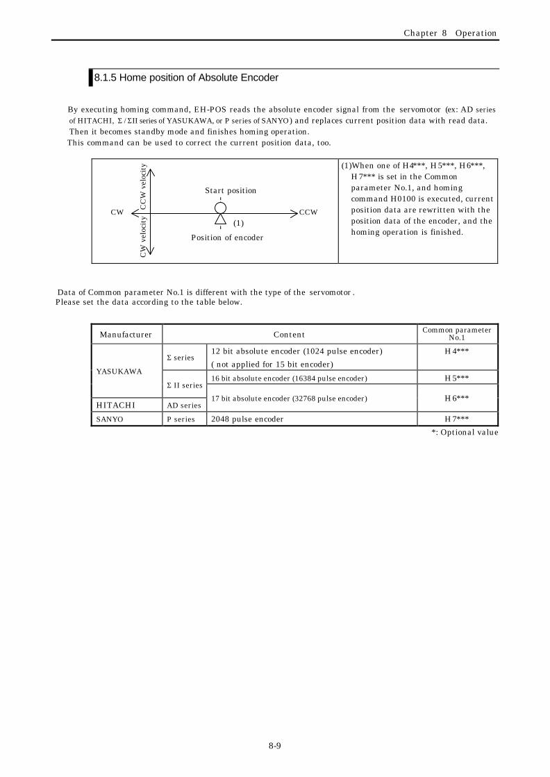
Chapter 8 Operation
8-9
8.1.5 Home position of Absolute Encoder
By executing homing command, EH-POS reads the absolute encoder signal from the servomotor (ex: AD seriesof HITACHI, Σ / ΣII series of YASUKAWA, or P series of SANYO) and replaces current position data with read data.Then it becomes standby mode and finishes homing operation.
This command can be used to correct the current position data, too.
(1)When one of H4∗∗∗, H5∗∗∗, H6∗∗∗,H7∗∗∗ is set in the Commonparameter No.1, and homingcommand H0100 is executed, currentposition data are rewritten with theposition data of the encoder, and thehoming operation is finished.
Data of Common parameter No.1 is different with the type of the servomotor . Please set the data according to the table below.
Manufacturer Content Common parameterNo.1
Σ series12 bit absolute encoder (1024 pulse encoder)
( not applied for 15 bit encoder)
H4∗∗∗
16 bit absolute encoder (16384 pulse encoder) H5∗∗∗YASUKAWA
Σ II series
HITACHI AD series17 bit absolute encoder (32768 pulse encoder) H6∗∗∗
SANYO P series 2048 pulse encoder H7∗∗∗
*: Optional value
CW(1)
Position of encoder
CCW
Start position
CC
W v
eloc
ity
CW
vel
ocit
y

Chapter 8 Operation
8-10
8.2 Manual Operation
8.2.1 Manual Operation1 ( Control Mode by External Input)
By writing H0200 into the control register (WY∗∗∗4), manual operation1 is set. When external inputmanual CCW (counter clockwise) is ON, forward pulses are output. When manual CW (clockwise) is ON,reverse pulses are output*1. When manual CCW or CW input signal time is fewer than 200ms, theinching operation (generating a single pulse) will be done.Until writing H07∗∗ to the control register (WY∗∗∗4), manual operation can be continued by ON/ OFF ofmanual input handling.
(1) Writes H0200 into WY∗∗∗4, andexecutes manual operation commandON. Then make M-CCW ON ofexternal input.
(2) After 200ms of a single pulse output,the motor starts with low homingvelocity, and accelerates up tomanual velocity.
(3) By making M-CCW off, The motorstops with slow down.
(4) Until Stop command (H0700 orH07FF) is written into Controlregister (WY∗∗∗4), manual operationis available.
(1) Writes H0200 into WY∗∗∗4, andexecutes manual operation commandON. Then make M-CW ON ofexternal input.
(2) After 200ms of a single pulse output,the motor starts with low homingvelocity, and accelerates up tomanual velocity.
(3) By making M-CW off, The motorstops with slow down.
(4) Until Stop command (H0700 orH07FF) is written into Controlregister (WY∗∗∗4), manual operationis available.
Notes*1: If both manual inputs M-CW and M-CCW are made ON at same time, the motor stops with
slow down. *2: To finish manual operation, execute the stop command (H0700 or H07FF) without fail.
Another command is not accepted. *3: In the operation, if the command (H0700) is written in, the motor stops with slowdown. If
the command (H07FF) is written in, the motor stops without slowdown.
NoticeIn manual operation, it is possible to operate even out of standby state. In other words, itis possible to operate at the state that homing operation is not finished. However, withoutcompleting homing operation, the current data are inaccurate.
Stop position
200ms
CW
Manualinput(M-CW)
(1)
(2)
(3)A single pulse
CCW
CC
W v
eloc
ity
CW
vel
ocit
y
ONOFF
Stop position
200ms
CW
Manualinput(M-CCW)
(1)
(2)(3)
A single pulse
CCWCC
W v
eloc
ity
CW
vel
ocit
y
OFFON

Chapter 8 Operation
8-11
8.2.2 Manual Operation2 ( Command Control Mode)
Manual operation command control mode is started by filling control register (WY∗∗∗) with H03∗∗.In this mode, start and stop control is done by commands. By this function, start and stop of the motor
(output control of pulse(s)) can be controlled by program written in the PLC, without concerning with theautomatic operation position data written in EH-POS.
Control Register
written dataCommand name
Indication on
PositionerContent
H03∗∗ Manual Operation Generation of pulse-train is controlled byStart and Stop commands.
H0300 Manual ForwardOperation
Generation of forward pulse-train iscontrolled by Start and Stop commands.
H0301 Manual ForwardJog Operation
Generation of single forward pulse iscontrolled by Start and Stop commands.
H0310 Manual ReverseOperation
Generation of reverse pulse-train iscontrolled by Start and Stop commands.
H0311 Manual ReverseJog Operation
MANUAL2
Generation of single reverse pulse iscontrolled by Start and Stop commands.
WY4=H0300R100=1
R7E
3
TD10R10
0TD10
0.1S 50
WY4=H0700
END
[Explanation]
(1)
(2)
(3)
(1) For one scanning after RUN, H0300 is setin WY4, and [the command to generateforward pulse-train in manual operation]is triggered. Then RUN LED (green) atthe front of EH-POS module is made ON.R100 is set with 1.
(2) When R100 is made ON (1), TD0 begins toincrease.
(3) After 5 seconds, TD0 is made ON, and WY4is set with H0700 (stop with slow downcommand). This command is executedimmediately. Then, RUN LED at thefront of EH-POS is made OFF, and STBLED is made ON.
(1) Manual Forward Operation (Generation of pulse-train) Continuous forward pulse-train is generated to write H0300 into Control Register WY∗∗∗4.
Stop of pulse-train generation is done by writing H0700 (stop with slowdown command) or F07FF (stop withoutslowdown command) into the same Control Register WY∗∗∗4.
(1) By writing H0300 into WY∗∗∗4,[Manual Forward Operation]command is executed.
(2) 200ms after single pulsegeneration, the motor is startedwith low homing velocity as initial,accelerated to manual velocity inacc./dec. time.
(3) Executing [Stop with slowdown]command by setting H0700 intoWY∗∗∗4,the motor is decelerated inacc./dec. time and stopped.
200ms
CW(1)
(2)
(3)A single pulse
CCW
CC
W v
eloc
ity
CW
vel
ocit
y
Stop position
Manual Velocity
Low Homing velocity
Acc./Dec. time
Stop with slowdown command
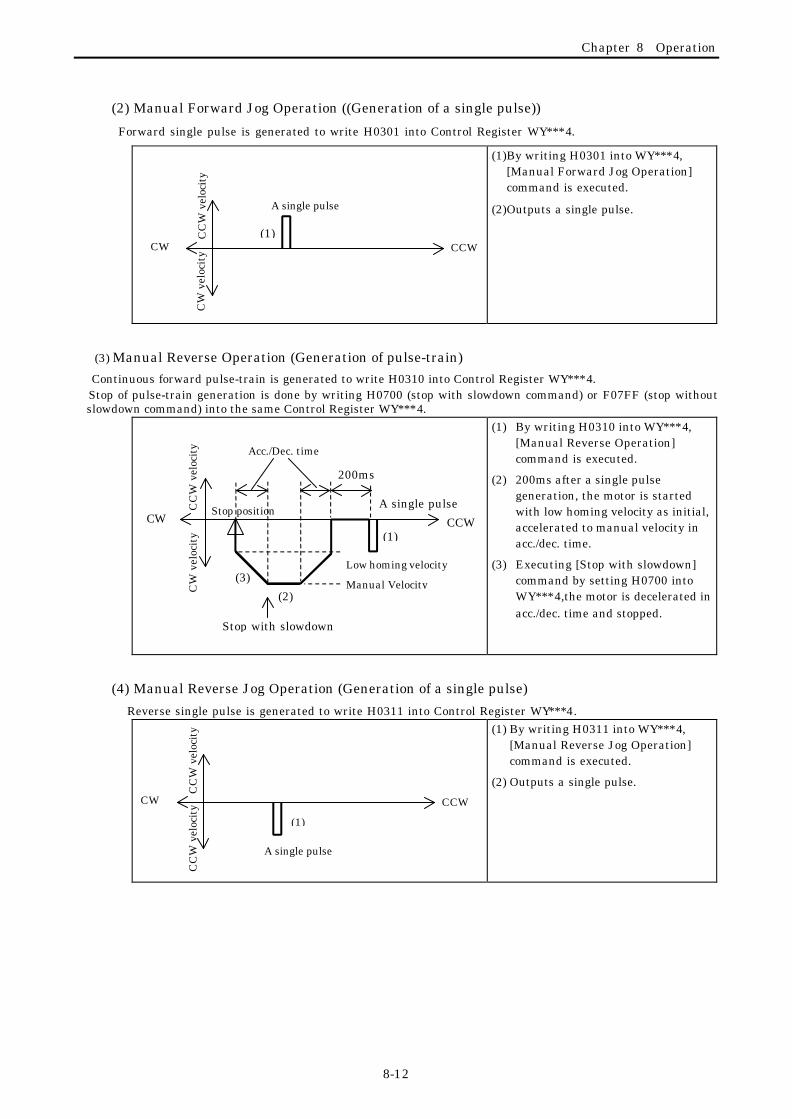
Chapter 8 Operation
8-12
(2) Manual Forward Jog Operation ((Generation of a single pulse))
Forward single pulse is generated to write H0301 into Control Register WY∗∗∗4.
(1) By writing H0301 into WY∗∗∗4,[Manual Forward Jog Operation]command is executed.
(2) Outputs a single pulse.
(3) Manual Reverse Operation (Generation of pulse-train)Continuous forward pulse-train is generated to write H0310 into Control Register WY∗∗∗4.
Stop of pulse-train generation is done by writing H0700 (stop with slowdown command) or F07FF (stop withoutslowdown command) into the same Control Register WY∗∗∗4.
(1) By writing H0310 into WY∗∗∗4,[Manual Reverse Operation]command is executed.
(2) 200ms after a single pulsegeneration, the motor is startedwith low homing velocity as initial,accelerated to manual velocity inacc./dec. time.
(3) Executing [Stop with slowdown]command by setting H0700 intoWY∗∗∗4,the motor is decelerated inacc./dec. time and stopped.
(4) Manual Reverse Jog Operation (Generation of a single pulse)
Reverse single pulse is generated to write H0311 into Control Register WY∗∗∗4.(1) By writing H0311 into WY∗∗∗4,
[Manual Reverse Jog Operation]command is executed.
(2) Outputs a single pulse.
200ms
CW(1)
(2)
(3)
A single pulse
CCW
CC
W v
eloc
ity
CW
vel
ocit
y
Stop position
Acc./Dec. time
Manual Velocity
Low homing velocity
Stop with slowdown
CW(1)
A single pulse
CCW
CC
W v
eloc
ity
CW
vel
ocit
y
(1)
A single pulse
CW CCW
CC
W v
eloc
ity
CC
W v
eloc
ity

Chapter 8 Operation
8-13
8.3 Automatic OperationIn automatic operation, the positioning operation is executed according to the automatic operation Position Data
prepared in advance. Three kinds of operation are prepared. They are automatic operation1 (a single stepoperation), automatic operation2 (a single cycle operation) and automatic operation3 (continuous cycle operation).
The operation is specified with the control command. Automatic operation of 256 steps is possible.
In case of starting automatic operation, it needs the standby state (the state operation is ready). The standby statecan be obtained by executing homing operation or manual operation.
Control Register
written dataCommand name
Indication on
PositionerContent
H04∗∗ Automatic operation1
(A single step operation)
RUN STEP One point positioning operation of thesingle step specified by ∗∗ of data
H05∗∗ Automatic operation2
(A single cycle operation)
RUN CYCL Continuous single cycle operation fromthe step specified by ∗∗ of data to thestep cycle stop bit is 1.
H06∗∗ Automatic operation3
(Continuous cycleoperation)
RUN CONT Continuous cycle operation from the stepspecified by ∗∗ of data to the step cyclestop bit is 1.
Automatic Operation Position Data is consisting of five kinds of data for every step. Data for a single step isshown below. For detail, refer 6.1.2 Automatic operation position data.
MSB LSBData
No.
Trans-missionWordNo.
15 to 12 11 to 8 7 to 4 3 to 0Content
Default Data(Hexadecimal)
1 1 Operation mode DwellOperation modeDwell(×20ms)
0 to 255 (HFF)
H8000
2 2 Acceleration time dataAcceleration time(ms)
1 to 65535 (HFFFF)H03E8(1000)
3 3 Deceleration time dataDeceleration time (ms)
1 to 65535 (HFFFF)
H03E8
(1000)
4 4 VelocityVelocity data
1 to 8000 (H1F40)
H0020
(0032)
5 Target position data (Lower)
5
6 Target position data (Upper)
Target stop position or speedchange position in continuousoperation+2,147,483,647 (H7FFFFFFF)
to -2,147,483,648(H80000000)
H00000000
(Note) 0 step of automatic operation position data are set with default values

Chapter 8 Operation
8-14
8.3.1 Automatic Operation1 (One Step Operation) Single Step Operation is started by writing H04∗∗ (∗∗ indicates step No. by hexadecimal) into controlregister WYrus4. At starting, standby bit is to be “1” (b9 of status register WX rus4). If standby bit isn’t“1”, operation isn’t executed. After started, pluses corresponding to the target point data come are output,then stops. Timing of each signal is as follows.
(1) Single Step Operation (When b13 of operation mode is “0”)
Start command (WY rus4 = H04∗∗)
Standby bit
Run bit
Finish of positioning (COIN)
Start point Target point Moving direction (*1)
Note*1: Moving direction is as follows.
Absolute mode: When target position data is bigger than current position data, it is CCW. When target position data is smaller than current position data, it is CW.
Increment mode: When target position data is plus (H1 to H7FFFFFFF), it is CCW. When target position data is minus (H80000000 to HFFFFFFFF), it is CW.
Initialvelocity
VelocityDecelerating
timeAccelerating
time
Dwell
Run bit becomes “0”after pulse is output andCOIN input is finished.
Standby bit becomes “1” after COINis input and dowel is finished.

Chapter 8 Operation
8-15
(2) A case of continuous operation with velocity change (b13 of operation mode is “1”)
Timing is shown below for the case that operation starts at step (H∗∗), and stops at next step (H∗∗ + 1)with changing velocity.
Start command(WYrus4 = H04∗∗)
Standby bit
Run bit
Finish of positioning (COIN)
Execute point Target point1 Target point2 Direction
Acceleration time1, Deceleration time1, Velocity1 and Target point1 are set at step ∗∗.Speed2 and Target point2 are set at step ∗∗+1. For Acceleration ratio*1, refer Caution below.
Initialvelocity
Velocity1 Decelerationtime1Acceleration
time1
Dwell
Acceleration ratio *1
1. Acceleration ratio for continuing steps is the one of start step.2. At the point of changing velocity, if direction of continuing step isn’t same as start step as the result of
velocity change, continuing step is neglected and next step is executed.3. When target point data of middle step is bigger than final target point data, the step is neglected. Example Suppose that start point is “0”, first target point is “1000”, second target point is “700”, third target point
is ”1500”, and final target point is “1200”. In this case it don ’t move to second “700” and third “1500” point.
0 700 1,000 1,200 1,500 neglected neglected Can’t move back
4. When the mode of continuing operation step is different from the one of former step, it doesn’t execute andbecomes command error.
Example A case that there are absolute mode and increment mode. A case that there are speed mode and position
mode.
5. When stop step of cycle operation is continuous operation, set “1” to cycle stop bit of all steps of continuousoperation.
Velocity2
Caution

Chapter 8 Operation
8-16
8.3.2 Automatic Operation2 (Single cycle Operation)
Single Cycle Operation is started by writing H05∗∗ (∗∗ indicates step No. by hexadecimal) into controlregister WYrus4. At starting, standby bit (b9 of status register WX rus4) is to be “1”. If standby bit isn’t “1”,operation isn’t executed.After started, every step is executed automatically until the step which cycle stop bit (b14) in operation
mode of automatic operation Position Data is set to “1”, Timing of each signal is as follows.
Execute command(WY***4 = H05∗∗)
Standby bit
Run bit
COIN
Dwell Dwell
Start point Target point[1] [2] [3] [4] [k] Distance, Time
Caution
1. It is permitted to have increment and absolute step in a cycle operation, but current position data isn’tcorrect. Please use the same mode in a cycle operation.
2. It is permitted to have position and speed mode in a cycle operation, but current position data isn’t correct.Please use same mode in a cycle operation.
3. When stop step of cycle operation is continuous operation, set “1” to cycle stop bit of all steps of continuousoperation.
Standby bit becomes “1” after COINis input and Dwell is finished.
Run bit becomes “0” afterpulse is output andCOIN input is finished.

Chapter 8 Operation
8-17
8.3.3 Automatic Operation3 (Continuous Cycle Operation)
Continuous Cycle Operation is started by writing H06∗∗ (∗∗ indicates step No. by hexadecimal) intocontrol register WYrus4. At starting, standby bit (b9 of status register WX rus4) is to be “1”. If standby bitisn’t “1”, operation isn’t executed.In this operation, The operation stated in 8.3.2 is executed repetitively, as shown below.[Start step (Target position k)→Stop step (Target position k+n) → Start step (Target position k)---]By setting Stop command (Stop with slow down or Emergency Stop), operation is stopped, and finished.
Distance, Time Start position Target position [k+1] [k+2] [k+3] [k+4] [k+n] (Target point k )
Continuous cycle

Chapter 9 Positioning module installation
9-1
Chapter 9 Positioning Module Installation
9.1 Loading the positioning module
(2)
(1)
(1) Installing
1) Hook the claw at the lower section of themodule to the hole in the base.
2) Press in the upper side of the module untilit clicks.
Note 1: After loading the module, check tomake sure it does not come out.
(2)
(1) (3) (2) Removing
1) Push in the lock button
2) With the lock button pushed in, pull the topof the module toward the front.
3) Raise it toward the top and pull it out.
9.2 Wiring to the power supply module
0 14 58 91 2 1 3
P O R T1
P O R T2
EH-150HITACHI
POWER
CircuitBraker orEarth leakageBraker
100 V AC
to 200 V AC
NoiseFilter
IsolationTransformer
(3) Wiring1) For power supply wiring, use a cable of 2
mm2 (0.0031 in2.) or more to prevent avoltage drop from occurring.
2) The function ground terminal (FEterminal) should use cable of 2 mm2
(0.0031 in2.) or more grounding (100 Ω orless). The appropriate distance forground cable is within 20 m (65ft.).a) The wiring can be shared with
instrumentation panel, relay panelgrounding
b) Avoid joint grounding withequipment that can generate noisesuch as high-frequency heatingfurnace, large power panel (severalkW or more), thyristor exchanger,electric welders, etc.
c) Be sure to connect a noise filer (NF)to the power cable.
3) The terminal screw is an M3. Whenwiring, tighten screws within a torquerange of 49 to 78 N·m.
4) Use the same power supply system forthe connected basic and expansion units.

Chapter 9 Positioning module installation
9-2
9.3 Wiring to the Positioning module
Multi-shielded twisted pair cable, which thickness is more than 0.25 mm or equal, should be used forpulse line output.Standard maximum cable length is 5 m.
9.3.1. Output wiring
(1) In case interface is 12/24 V level and optical coupler is used
(2) In case interface is line-receiver
( Note 1) Though shielding of the output cable is recommended to be grounded at a cable end of receivingside (input side) as a rule, according to noise environment and grounding condition, other ways, like nogrounding or grounding at transmitting side, are sometimes better. Please select best way in eachapplication.
( Note 2) If cable length is long, then output pulse becomes delayed and when output frequency is high,position controller side might not receive signals correctly. Cable length is recommended to be short asmuch as possible. Though cable length is influenced by kind of cable and load of position controller,standard cable length is recommended to be max. 5m.
( Note 3) Signals of servo amplifier are different between manufacturers’ types. Wiring is to be startedafter confirming the specifications of the servo amplifier adopted.
(Note 3)
Position controller(Note 1) (Note 2)
PULS-P
PULS-
(Note 3)
SIGN-P
SIGN-N
12/24 V DC+12/24 V DC-
Position controller(Note 1)
FG
P5G
CCW
CW
5V DC+
Internalcircuit
Positioning module
(Note 2)
5V DC+
5V DC-
+
+
FG
CCW-
CCW+
CW-
CW+PULS-P
PULS-N
SIGN-P
SIGN-N
5V DC+
P5G
5V DC+
5V DC-
Internalcircuit
Positioning module

Chapter 9 Positioning module installation
9-3
9.3.2. Caution of Input / output wiring
( Note ) I/O cables of positioning module are to be wired separately from power cables and AC I/O cables.
l I/O wiring of EH-POS is to be separated from power lines and wiring of AC input/output modules.l When I/O wiring is cut by accident, or a component of PLC (including EH-POS) is broken down, the
motor in the system may move unexpectedly.For failsafe, prepare protection means for operator(s) and machine(s) such as Emergency Stop Circuit,Protection Circuit and Interlock Circuit of PLC system, against unusual operation of the system.
Power cables
AC I/O cables
DC I/O, Positioning I/O cables
30 cm or more
Caution

Chapter 9 Positioning module installation
9-4
9.4 Example of wiring with a Servo Amplifier
9.4.1 Example of wiring with Hitachi AD series (increment)
1st
ポ ジ シ ョ ナP O S I T I O N E R
HITACHI
4
2nd
5 6
987
3
FWD REVSTOP
2 3
1
4
0
1 2
D E L I N S
CLR
MODE
CAN CEL
STR 2nd
C O N N E C T T H E R E M O T E C A B L E WITH
C O N T R O L L E R A F T E R T U R N N I N G O F F T H E
I N P U T P O W E R O F C O N T R O L L E R
リ モ ー ト ケ ー ブ ル の 接 続 は 必 ず コ ン ト ロ ー ラ
の 電 源 を 切 っ て か ら 行 っ て く だ さ い 。
7 CCW+8 CCW-5 CW+
6 CW-
PLSP 15
PLSN 16SIGP 40
SIGN 41
9 C+10 C-13 COIN
OZP 23OZN 24INP 12
E H - 1 5 0
RESET
CN1
CN2
NF
1 P5V
2 P5G
15 +O.RUN
16 -O.RUN
+24V DC
17 MODE-SEL18 M-CW19 M-CCW
+5V DC
20 COM
CM2 34
RS 27SON 26FOT 28
ROT 29
PEN 33
PLC 2MOD 3
Magnetcontactor
AD ADA-08LSseries
AC SERVO HITACHI
NF

Chapter 9 Positioning module installation
9-5
9.4.1 Example of wiring with Hitachi AD series (absolute)
1st
ポ ジ シ ョ ナP O S I T I O N E R
HITACHI
4
2nd
5 6
987
3
FWD REVSTOP
2 3
1
4
0
1 2
D E L I N S
CLR
MODE
CAN CEL
STR 2nd
C O N N E C T T H E R E M O T E C A B L E WITH
C O N T R O L L E R A F T E R T U R N N I N G O F F T H E
I N P U T P O W E R O F C O N T R O L L E R
リ モ ー ト ケ ー ブ ル の 接 続 は 必 ず コ ン ト ロ ー ラ
の 電 源 を 切 っ て か ら 行 っ て く だ さ い 。
7 CCW+8 CCW-5 CW+
6 CW-
PLSP 15
PLSN 16SIGP 40
SIGN 41
11 PS-12 PS+13 COIN
OZN 24OZP 23INP 12
E H - 1 5 0
RESET
CN1
CN2
NF
1 P5V
2 P5G
15 +O.RUN
16 -O.RUN
+24V DC
17 MODE-SEL18 M-CW19 M-CCW
+5V DC
20 COM
CM2 34
RS 27SON 26FOT 28
ROT 29
PEN 33
PLC 2MOD 3
Magnetcontactor
AD ADA-08LSseries
AC SERVO HITACHI
NF

Chapter 9 Positioning module installation
9-6
9.4.3 Example of wiring with Yasukawa Σ II series (absolute)
1st
P O S I T I O N E R
HITACHI
4
2nd
5 6
987
3
FWD REVSTOP
2 3
1
4
0
1 2
DEL INS
CLR
MODE
CAN CEL
STR 2nd
CONNECT THE REMOTE CABLE WITHWWITHCONTROLLER AFTER TURNNING OFF THEINPUT POWER OF CONTROLLER
EH-150NFRESET
CN1
CN2
L1L2+ 1- 1
-L1CL2CB1B2UVW
Magnetcontactor
+5V 1 P5V
CN1
CN2
CN3
5 CW+6 CW-7 CCW+8 CCW-
PULS*PULSSIGN*SIGN
2 P5G0V
9 C+10 C-11 PS-12 PS+
PCO*PCO*PSOPSO
13 COIN
14 PORG15 +O.RUN16 -O.RUN
20 COM +24V
17 MODE-SEL18 M-CW19 M-CCW
NF
+5VSEN
SG0V
COIN+
0V COIN-

Chapter 10 Erroe Code List
10-1
Chapter 10 Error code listThere are two kinds of error code indication as below.(1) Execution error indication command code ( H5000 ) by user program or forced Set/Reset, and store
error code into WX∗∗∗2.(2) Indicate error code on a display of Positioner (optional operator) by selecting “Error Code Indication
Menu” in “Monitor Mode” by the Positioner. Please take countermeasures against errors based on the error list below.
¡: Continue RUN ×: Stop RUN
Group Error Code Contents
Beha-vior
Clearing timing
H0001 A control command other than STOP command wasreceived during RUN. Received command is to beignored.
¡
H0002 ReservedH0003 Control mode of automatic RUN (data No.1 of position
data of automatic RUN.) is set in undefined mode.×
H0004 In case velocity data of automatic RUN (data No.4 ofposition data of automatic RUN) is smaller than aninitial velocity (parameter No.5 of commonparameters), EH -POS starts with the velocity data asan initial velocity.
¡
At executingcommunicationinitial command(H5100) orresettingcontrolcommands
H0005 In case acceleration time of automatic RUN ( data No.2of position data of automatic RUN) is smaller thanmin. available acceleration time, EH-POS accelerateswith the min. available acceleration time.
¡
H0006 In case deceleration time of automatic RUN (dataNo.3 of position data of automatic RUN) is smallerthan min. available deceleration time, EH-POSdecelerates with the min. available deceleration time.
¡
H0007 Velocity data of automatic RUN (data No.4 of positiondata of automatic RUN) is 0.
×
H0008 In case initial velocity data (parameter No.5 ofcommon parameters) is 0, EH-POS start with the min.available velocity.
¡
H0009 There is a step which has a different running mode ina continuous RUN (refer to data No.1of position dataof automatic RUN).
×
H0010 No. of steps is 11 or bigger(refer to data No.1ofposition data of automatic RUN).
×
H0011 ReservedH0012 Starting step is invalid ×H0013 ReservedH0014 ReservedH0015 ReservedH0016 In case acceleration time of manual RUN and High-
speed homing (common parameter No.2) is smallerthan min. available acceleration time; EH-POSaccelerates with the min. available acceleration time.
¡
H0017 In case initial manual velocity (parameter No.5 ofcommon parameters) is 0 in manual RUN,EH-POS starts with the min. available velocity.
¡
H0018 Manual velocity (parameter No.5 of commonparameters) is 0 in manual RUN
×
Com
ma
nd
error
H0019 At homing low-speed return velocity (Parameter No.7of common parameter) is 0.
×
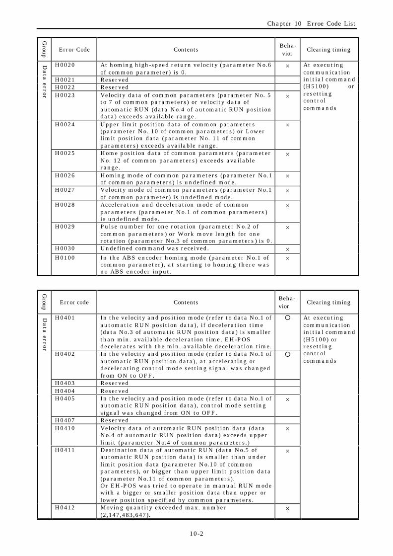
Chapter 10 Erroe Code List
10-2
Group Error Code Contents
Beha-vior
Clearing timing
H0020 At homing high-speed return velocity (parameter No.6of common parameter) is 0.
×
H0021 ReservedH0022 ReservedH0023 Velocity data of common parameters (parameter No. 5
to 7 of common parameters) or velocity data ofautomatic RUN (data No.4 of automatic RUN positiondata) exceeds available range.
×
At executingcommunicationinitial command(H5100) orresettingcontrolcommands
H0024 Upper limit position data of common parameters(parameter No. 10 of common parameters) or Lowerlimit position data (parameter No. 11 of commonparameters) exceeds available range.
×
H0025 Home position data of common parameters (parameterNo. 12 of common parameters) exceeds availablerange.
×
H0026 Homing mode of common parameters (parameter No.1of common parameters) is undefined mode.
×
H0027 Velocity mode of common parameters (parameter No.1of common parameter) is undefined mode.
×
H0028 Acceleration and deceleration mode of commonparameters (parameter No.1 of common parameters )is undefined mode.
×
H0029 Pulse number for one rotation (parameter No.2 ofcommon parameters ) or Work move length for onerotation (parameter No.3 of common parameters ) is 0.
×
H0030 Undefined command was received. ×
Da
ta error
H0100 In the ABS encoder homing mode (parameter No.1 ofcommon parameter), at starting to homing there wasno ABS encoder input.
×
Group Error code Contents
Beha-vior
Clearing timing
H0401 In the velocity and position mode (refer to data No.1 ofautomatic RUN position data), if deceleration time(data No.3 of automatic RUN position data) is smallerthan min. available deceleration time, EH-POSdecelerates with the min. available deceleration time.
¡
H0402 In the velocity and position mode (refer to data No.1 ofautomatic RUN position data), at accelerating ordecelerating control mode setting signal was changedfrom ON to OFF.
¡
H0403 ReservedH0404 ReservedH0405 In the velocity and position mode (refer to data No.1 of
automatic RUN position data), control mode settingsignal was changed from ON to OFF.
×
H0407 ReservedH0410 Velocity data of automatic RUN position data (data
No.4 of automatic RUN position data) exceeds upperlimit (parameter No.4 of common parameters.)
×
H0411 Destination data of automatic RUN (data No.5 ofautomatic RUN position data) is smaller than underlimit position data (parameter No.10 of commonparameters), or bigger than upper limit position data(parameter No.11 of common parameters).Or EH-POS was tried to operate in manual RUN modewith a bigger or smaller position data than upper orlower position specified by common parameters.
×
At executingcommunicationinitial command(H5100) orresettingcontrolcommands
Da
ta error
H0412 Moving quantity exceeded max. number(2,147,483,647).
×
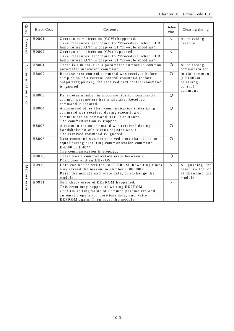
Chapter 10 Erroe Code List
10-3
Group Error Code Contents
Beha-vior
Clearing timing
H0801 Overrun to + direction (CCW) happened.Take measures according to “Procedure when O.R.lamp turned ON ” in chapter 11 “Trouble shooting ”.
× At releasingoverrun
Ov
errun H0802 Overrun to – direction (CW) happened.
Take measures according to “Procedure when O.R.lamp turned ON ” in chapter 11 “Trouble shooting ”.
×
H8001 There is a mistake in a parameter number in commonparameter indication command.
¡ At releasingcommunication
H8002 Because next control command was received beforecompletion of a current control command (beforeoutputting pulses), the received next control commandis ignored.
¡ initial command(H5100) orreleasingcontrolcommand
H8003 Parameter number in a communication command ofcommon parameters has a mistake. Receivedcommand is ignored.
¡
H8004 A command other than communication initializingcommand was received during executing ofcommunication command H4F00 or H48**.The communication is stopped.
¡
H8005 A communication command was received duringhandshake bit of a status register was 1.The received command is ignored.
¡
H8006 Next command was not received more than 1 sec. orequal during executing communication commandH4F00 or H48**.The communication is stopped.
¡
Com
mu
nica
tion error
H8010 There was a communication error between aPositioner and an EH-POS.
¡
H0910 Data can not be written to EEPROM. Rewriting timesmay exceed the maximum number (100,000).Reset the module and write data, or exchange themodule.
×Mem
ory error
H0911 Sum check error of EEPROM happened.This error may happen at writing EEPROM.Confirm setting value of Common parameters andautomatic operation positions data, and writeEEPROM again. Then reset the module.
×
At pushing thereset switch orat changing themodule

Chaputer 11 Trouble shooting
11-1
Chapter 11 Trouble shootingThis chapter describes the errors at operation. There are major five kinds of error indication as follows.
(1) LED Indication in front of EH-POS(2) Status register (WX∗∗∗0) Indication(3) Positioner (option) Indication(4) EH-CPU Indication(5) No error indication on EH-POS and EH-CPU but abnormal motor operation
11.1 Error indication of LED
LED ERROR
or Function
Content Countermeasure LED atabnormal
POW Power LED No power (Power LED of Powermodule is turned off).The module is not mounted inbase correctly.
Check the power supply is added.Check the connection of moduleand mount module correctly.
off
WDE Watch dogtimer error
MPU in EH-POS has an error. Push RESET switch.Reset the power supply.
on
O.R Overrun error Overrun state occurred.(In case DIP switch No.5 and 6are OFF, and external inputsignal ofoverrun is valid.)
Release the overrun state inmanually, and perform return tostarting again.In case the external input signal ofover RUN is not used, setDIPswitch No.5 and 6 on to beinvalid it (Refer 11,12).
on
CMDE Command error Command error occurs. Check the error code inWX∗∗∗2 by executing errordisplay command (H5000).Perform error recoveryprocedures according tochapter 10. error code list.
on
Note: At power off, “WDE” LED lights for a moment, but this is not abnormal.

Chaputer 11 Trouble shooting
11-2
11.1.1 Trouble shooting procedure for WDTE LED on. (Module abnormal)
Make power off, put off themodule, and observe it visually.
WDTE LED lights
Push RESET switch or makepower off and on.
Normal?It seems temporary abnormaldue to noise.Watch the state for awhile.
No
Is the connector pinbent?
No
Yes
If the bent pin is not critical, correct it.Contact with our distributor office if the bent pinis critical or if the system operation is stillabnormal after correcting the bent pin.
Bent
Replace with a spare module. Ifthe system works abnormallyafter replacement, or any sparemodule is not prepared, contactwith our distributor office.

Chaputer 11 Trouble shooting
11-3
11.1.2 Trouble shooting procedure for O.R lamp on (Overrun error)
Take the following procedures to recover from an overrun error. The case of –O.RUN is explained below (In case of +O.RUN, the direction is the opposite.)
Abbreviation: –O.RUN = Overrun of clockwise (CW) direction+O.RUN = Overrun of counterclockwise (CCW) directionO.RUN = Overrun including –O.RUN and O.RUN
(1) Move the system manually in the direction where O.RUN is released.(2) Confirm the release of O.RUN. When the O.RUN is released, OR lamp turns off.(3) Move the system manually toward a positive position of the starting point or a position within the
home LS.(4) Execute return to starting point.(5) Execute normal operation.
An error occurred.
(1), (2)
(3)
(4)
Homeposition
Home LS
–O.RUN +O.RUN
Recovery procedures from an overrun error (in case of –O.RUN)

Chaputer 11 Trouble shooting
11-4
11.2 Error indication of LEDThe error bit of the status register is set to “1” when data error, command error or communication erroroccur.
Statusregisterdisplay
Name of error Description Countermeasure
H∗ 4∗ ∗H∗ C∗ ∗
Overrun error Overrun occurred. Refer to Trouble shootingprocedure of this chapter(11.1.1).
H3∗ ∗ ∗H1∗ ∗ ∗
Data error or commanderror
Data error or command erroroccurred.(Note1)
H8∗ ∗ ∗HC∗ ∗ ∗
Communication error Communication erroroccurred
Refer to the Error code list inchapter 10.
Note1: After error is released, if communication initializing command (H5100) is not issued, the display showsH1∗∗∗.
11.3 Error display at Positoner(Option)When error code display is selected in monitor mode, error code will be displayed on display part. Referto chapter 14 for operation of positioner. Refer to chapter 10 for error code in detail.
11.4 Error display on EH-CPUWhen watchdog timer error occurs at EH-POS, EH-CPU displays error as module abnormal.Refer to the application manual of EH-150 in detail.
11.5 Abnormal operation of Motor
No. item explanation / countermeasure
1 Is the I/O allocation correct? Confirm I/O allocation of EH-POS.I/O allocation of EH-POS is “word 4W/4W”. Otherwise, EH-POS operation isabnormal or no operation in wrong I/O allocation.
2 Is the wiring proper? Check the connection of the output terminal of EH-POS and the inputterminal of motor controller. In case of O.RUN error, refer to section 11.1.2
3 Does the setting ofDIPswitch No.1 and 2, matchwith the pulse outputmethod of EH-POS, and thepulse-input method of motorcontroller?
In case of the mismatch, one of the following abnormal operations is caused. (a) The motor runs only in one direction. (b) An error occurs to the motor controller. (c) The motor running direction changes in a short interval.
4 Is EH-POS in stand-by modebefore automatic operation?
When automatic operation is executed, EH-POS must be in stand-by mode.By executing homing or manual operation command, set EH-POS in stand-by mode.
5 Are connectors connected?Is the connector pin bent?
When I/O connectors are not inserted exactly or connector pin is bent, signalsare not transferred correctly, the motor may cause miss-operation or maynot move.
6 Isn't pulse generated evenindication of current positionchanges in manual operationor automatic operation?
If No.1,2 and 4 above are correct, then module trouble is guessed. In thiscase please contact with our distributor office.

Chapter 12 Comparision with POSIT-2H
12-1
Chapter 12 Comparison with POSIT-2H
12.1 Comparison with POSIT-2HEH-POS has additional functions shown below against POSIT-2H and POSH for H-series PLC.
(1) It is possible to select a type of homing (Return to home position).Type of returning to (arbitrary, low-speed, high-speed) and direction (forward, reverse) can beselected in common parameters.
(2) Acceleration time and deceleration time can be specified individually in automatic operation mode.Acceleration time and deceleration time are specified individually at each step in automaticoperation mode. In return to home point mode and manual operation mode, they are performed atvalue with acceleration/deceleration time being set in common parameter.
(3) S-shaped acceleration/deceleration function is added.Trapezoidal or S-shaped (3-kind) acceleration/deceleration can be set in common parameters.
(4) Line driver output of pulse output method is added.Open collector output and line driver output are available on different terminal at same time.(CW/CCW, Clock/direction are specified with DIP switch No.1 and 2 at side of EH-POS module.
(5) It is possible to select a valid/invalid of external input signals (COIN, +O.RUN, -O.RUN).The eternal input signals (COIN, +O.RUN, -O.RUN), which is usually ON in normal operation, canbe specified in valid or invalid. This is usable to operate before wiring of COIN,+O.RUN and -O.RUN signals.The selection of valid/invalid is set with DIPswitch No.4,5 and 6 at side of EH-POS module.
(6) Command code is extended according to the addition or extension of function.(a) The velocity change in RUN mode (addition of H8000)
This is available in homing mode and automatic operation mode.(b) Current position data update (addition of H4DFF) Current position data update command (H4DFF) is supported in communication command.(c) Restart after stop command
It is possible to restart after deceleration stop (H0700) and Emergency stop (H07FF). (Systemkeeps stand-by.)
(d) Handshake procedure in display command The handshake procedure is added to ensure the procedure.
(7) ABS encoderEncoder type is specified in homing mode in common parameters.
(Applied manufacturer and series: HITACHI AD series, Yasukawa Σ series/Σ II series, Sanyo P series)
(8) Content of status register is changed.Run latch bit and error latch bit are added.

Chapter 12 Comparision with POSIT-2H
12-2
12.2 Command Comparison with POSIT-2HThe table below shows the commands added to EH-POS against POSIT-2H.
Table 12.1 Comparison of Control Command
POSIT-2H EH-POS Changed/
No.
Controlregister
WY***4
writtenvalue
Command
name
Content Command
name
Content added
1 H0000 HALT Deceleratedstop
Undefined The command isignored.(Countermeasure of I /Orefresh)
C h a n g e d
H03** Manual 2 Teachingsetting
Manualoperation
This commandgenerates pulse, and itis stopped by stopcommand.
A d d e d
H0300 Undefined – Forwardmanualoperation
This commandgenerates forwardcontinuous pulse.
A d d e d
H0301 Undefined – Forward JOG operation
This commandgenerates forward onepulse (JOG).
A d d e d
H0310 Undefined – Reversemanualoperation
This commandgenerates reversecontinuous pulse.
A d d e d
2
H0311 Undefined – Reverse JOGoperation
This commandgenerates reverse onepulse (JOG).
A d d e d
H07∗ ∗ Undefined – Stop The system is stoppedand is set to stand-bymode .
A d d e d
H0700 Undefined – Slow downand stop
The system isdecelerated and stop.
A d d e d
3
H07FF Undefined – Emergencystop
The system stopswithout deceleration.
A d d e d
4 H8000 Stop Emergencystop
Velocitychange
This command changesthe velocity in RUNmode. The stored data isnot changed.
C h a n g e d
5 H84∗ ∗ Undefined – Velocity andposition dataspecifiedautomaticstep operation
Automatic stepoperation is performedby the control mode,acceleration time anddeceleration t ime,which are used in the∗ ∗ step data and thespecified data ofvelocity and position inoperation.
A d d e d

Chapter 13 Programming
13-1
Chapter 13 Programming exampleWhen EH-CPU issues three kinds of command such as communication, operation and display command, and the
EH-POS executes these commands. Program to issue above three commands are called as communication program,operation program, data read program individually. In this chapter, these three programs are explained.
13.1 Caution on programmingEH-POS can not recognize the second command or later when it receives the same command twice continuously,
because of EH-CPU refresh processing. Therefore when you want to write the same command continuously to thecontrol register, write the communication initial command (H5100) or the other command in the next scan.
13.2 Communication programCommunication program is the program, which writes the communication command in 6.3.2 to control register
(WYrus4). EH-POS sets data (common parameter, automatic position data) on EH-POS in transmission are(WYrus5 to 7) according to communication command. Therefore setting data must be write in transmission areabefore issuing communication command.(Communication command and setting data may be write in the scan,
Because of EH-CPU refresh processing.)
CautionWhen data are set to EH-POS, they are stored in the internal memory (EEPROM) and such data
are retained in case of power failure.Therefore, once data are set by program, no communication program is required. However store
the data set in the memory onto an external storage device such as floppy disk, preparing for theaccidental memory damage. If it is not available, record the data on setting sheet attached at the endof the manual, and keep it. It is possible to rewrite data individually by executing the communicationcommand, which is driven by Forced Set/Reset function. (Refer to 6.3.2 Communication command fordetails.)
The content of EEPROM can be rewritten up to about 100,000 times. It is not guaranteed torewrite more than about 100,000 times.

Chapter 13 Programming
13-2
Data are transferred from the EH-CPU to EH-POS using 3-word transmission area (WYrus5 to 7). Thereforerepeating 5 times of transmission process is required to update all the 15 words of common parameter (whencommunication command is H4F00), while two repeating of transmission process is required to update all 6 words ofthe automatic operation data for one step (when the communication command is H48∗∗. Here ∗∗is the step No.).Refer to Chapter 7 for details of communication procedure.
R7E3
Single scanafter RUNstart
WR1 = H0000 (Homing, Velocity coefficient, Unit)
WR2 = 2000 (Pulse No. for a rotation)
WR3 = 2000 (Moving distance of work for a rotation)
WR4 = 8000 (Velocity upper limit of)
WR5 = 16 (Initial velocity)
WR6 = 32 (Manual operation / High speedoperation Homing velocity)
WR7 = 16 (Low speed operation homingvelocity)WR8 = 1000 (Acc./Dec. time)WR9 = 0 (Backlash offset)
DRA = H3FFFFFFF (Upper limit position data)
DRC = HC0000000 (Lower limit position data)
DRE = 0 (Home position data)
(00001)
R7E3
Single scanafter RUNstart
WR101 = H8000 (Control mode, Dwell)
WR102 = 1000 (Acc.time)
WR103 = 1000 (Dec.time)WR104 = 32 (Velocity)
DR105 = 10000 (Target position 10000)
(00002)
Setting value
of commonparameter
Setting valueof automaticoperationposition data
R100
Trigger to setcommonparameter
R0 = 1
WR20 = 0WR21 = 0
(00003)
Initialization ofvariables
DIF0
R101
Trigger to setautomatic operationposition data
R1 = 1WR20 = 0
WR21 = 0
(00005)
Initializationof variables
DIF1
R0CAL 0
(00004)
Subroutine call
R1CAL 1
(00006)
END (00007)
Parameterset
Subroutine Callfor commonparametersetting
Subroutine Callfor automaticoperationposition datasetting
End of scanning
(Example) In case of setting Common parameter all data set (H4F00), and setting of One step positiondata set (H4800) for Step00. (Following description is the case that EH-POS is put on slot 0.)
Subroutine call

Chapter 13 Programming
13-3
SB 0 (00008)
WY4 = H5100 (00009)
X14
WY5 = WR1 (WR21)WY6 = WR2 (WR21)WY7 = WR3 (WR21)WY4 = H4F00WR20 = WR20 + 1WR21 = WR21 + 3
(00010)
X14
WY4 = H4F00 AND HBFFFWR20 = WR20 + 1
(00011)X14
WR20==0
WR20==0
WR20==2
WR20==4
WR20==6
WR20==8
WR20==1
WR20==3
WR20==5
WR20==7
WR20==9
WR20==10
R0 = 0 (00012)
RTS (00013)
Handshakebit of Statusregister
Trigger of
Commonparametersettingcommand
Subroutine forCommonparameter datasetting
Clear thehandshake bitof Controlresister
Trigger of Communication
Initializing command(H5100)

Chapter 13 Programming
13-4
NoticeIn case of rewriting all of common parameter 15 words (in this case, Communication command
H4F00 is used), rewrite by three words by five times, within one second. If more than one secondelapsed for this setting, the communication error occurred (Error code is H8006 then). Refer to 7.1.1 Setting Communication Flow)
In case of rewriting all of automatic operation data 6 words for one step (in this case,Communication command H8∗∗ is used), rewrite with in one second or less. (Refer to 7.1.1 Setting Communication Flow)
SB 1 (00014)
WR20==0
WY4 = H5100 (00015)
X14
Trigger ofautomaticoperation positiondata set command
(H48∗∗)
(∗∗ : Step No.)
WR20==0
WY5 = WR101 (WR21)WY6 = WR102 (WR21)WY7 = WR103 (WR21)WY4 = H4800WR20 = WR20 + 1WR21 = WR21 + 3
(00016)
X14
WR20==2
WR20==1
WY4 = H4800 AND HBFFFWR20 = WR20 + 1
(00017)
X14
WR20==3
WR20==4
R1 = 0 (00018)
RTS (00019)
Subroutine Callfor automaticoperationposition datasetting
Handshake bit ofStatus register
Clear thehandshake bitof Controlresister
Trigger of Communication
Initializing command(H5100)

Chapter 13 Programming
13-5
13.3 Operation program
Operation program is program, which writes the control command shown in 6.3.1 into control register (WYrus4).EH-POS will do the operation such as homing, manual operation, automatic operation, stop the operation and so on.
(Example) After homing operation, automatic step operation (Step No. 0) is executed. (Following description is thecase that EH-POS is put on slot 0.)
This program will operates as follows.(1) By setting internal output R0 with 0, homing operation is executed.[Circuit No.1](2) On-delay timer TD0 starts to count up. [Circuit No.2](3) When the current value of TD0 reached to 20mS, automatic step operation starts. [Circuit No.3]
NoticeBy using Forced Set/Reset function in Monitor mode of programming tool, you can execute the
operation command, without using sequence program by ladder diagram. In this case, set the controlcommand into the Control Register (WYrus4).
The current position is displayed on display area of the memory (WXrus2 and WXrus3).
R0
Start of Return tohome operation
WY4 = H100 (homing)
R100 = 1
(00001)
WY4 = H400(Operation of Step No.0)
(00003)
(00002).0ls 2
TD0
TD0R100
Trigger ofautomatic Stepoperation
Trigger ofDisplaycommand
DIF0

Chapter 13 Programming
13-6
13.4 Data readout program
Data readout program is the program to write the Display command shown in 6.3.3 into Control Register(WYrus4). By the command written, EH-POS will read the data (Common Parameter or automaticOperation Position data), Error code and other data, which is set in the EH-POS.
To get data in the display area, at least one scanning time is necessary after writing the Display Codeinto Control Register (WYrus4). When you make data readout program, make sure to keep the above.Usually, to send data into CPU, one scanning time is necessary.
(Example) After homing operation, automatic step operation (Step0) is executed. (Following descriptionis the case that EH-POS is put on slot 0.)
This program will operates as follows.(1) By setting internal output R0 with 1, Current Position Data display command is executed.[Circuit
No.1](2) On-delay timer TD0 starts to count up. [Circuit No.2](3) When the current value of TD0 reached to 20mS, current position (upper) is set in WR10, and
current position (lower) is set in WR20. [Circuit No.3]
NoticeReadout of individual data can be done by Forced Set/Reset function in the Monitor mode of the
programming tool. In this case, the sequence program of the ladder diagram is not necessary.Especially, when no data back up is needed, or data (which is used in setting communication
program) is backed up by floppy disk, Sequence program is not necessary.
By using Forced Set/Reset, set the communication command into Control Register (WYrus4).
Readout data is displayed on the Display area (WXrus2 and WXrus3).
R0
Start of Displaycommand
WY4 = H5800
(Display of Current position)
(00001)Trigger ofDisplaycommand
DIF0
R100
(00003)
(00002).0ls 2
TD0 WR10 = WX3 WR20 = WX2 R100 = 0
TD0

Chapter 13 Programming
13-7
13.5 Example of simple program and operation The programs (communication program, operation program and data read program) are usually used incombination. In this section, a simple program combining these three programs and its operation isexplained.
13.5.1 Configuration
(1) Installation position is shown below.0 1 2 3
PowerEH-CPU
EH-POS
16-pointinput
16-point
output
16-point
output
(2) I/O allocation is shown below. CPU setting: EH-150 I/O assignment (Standard I/O assignment)
Unit No.
Slot No.
(3) For external wiring, refer to Chapter 9 Positioning module installation.
13.5.2 Explanation of Execution
This program executes operation below.(1) When R1 is turned on, common parameter is set with the default value.(2) When X100 is turned on, homing operation is done.(3) When X101 is turned on, it turns to manual positioning operation mode.(4) When X102 is turned on, the current position data is shown on slot2 and slot3.
(Lower word is shown on slot3 and upper word is shown on slot2.)(5) When X103 is turned on, the motor stops after slow down (deceleration).
(When motor is in Stop State, ending procedure of manual operation is done.)
0123456789ABCDEF
Word 4W/4W1 30 2 4
X16Y16Y16

Chapter 13 Programming
13-8
13.5.3 Program
(1) Program list
Commonparametertransmissionstart
R1=0
R2=1 (Under Common parameter
R3=0 transmission executing.)commonparametercommunicationstarts
underexecution
R1 X14 R2(00001)
R4=X14 (Substitute handshake bit for R4) WR10=H4D00 (Substitute communication
command for WR10)
CAL 0under
execution
R2
(00002)
Commonparametertransmissionunderexecution
handshakebit
(00003) WY4=H100 (issue Return to home command)
(00004)
Homing
X200 DIF0
Homing
manualoperation
X201 DIF1Manualoperation
(00005) WY4=H1800 (issue display command)
R5=1data readstarts
X202 DIF2
Start of readingcurrent position
R5 TD0 (00006).0ls 2Timer for display
data
TD0Display currentposition
WY20=WX3
WY30=WX2
(Display current position on slot 2,3)
R5=1
END
(00007)
(00009)
SB 0 (00010)
Commonparametertransmissionsubroutine
WY4=WR10
(Issue communication command in WR10)
R3=0
R3=1
R3 R4(00012)
R2=0
R3=0
WY4=WY4 AND HBFFF
(Clear a handshake bit)
R3 R4(00013)
(00014) RTS
Subroutine program
Data R
ead Program
Com
mu
nication
programO
perationprogram
WY4=H700
(Issue of command Stop with slow down)
(00008)X103 DIF3
Stop with slowdown, or end ofmanual setting
Operation
program
WY4=H200 (issue manual operation command)
WY4=WR10
(Issue Communication initializing command)
R3 R4(00011)

Chapter 13 Programming
13-9
(2) Bit and word allocationThe operation is started by setting the bit marked by * in the table to “1”.
Table 13.5.3 Internal bit and word listCircuit No.
be usedProgram to be used I/O No. Function and Description
R1 Common parameter transmission starts ∗R2 Common parameter is under sending
R3Handshake control flag (Sets the handshake bit to”1”by communication command issued, and to “0” bycommunication completes.)
R4The value of the handshake bit of status register 1(set “1” after data setting completes)
1 to 211 to 13
Communication program(include Subroutine)
WR10Communication commandIndicates the communication command to be set tothe control register in communication
X100Input of the return to starting point operation start ∗
X101 Input of the manual operation mode start3 to 4,8 Operation program
X103Start input of Stop with slow down ∗Or input to finish manual operation
R5 Start Timer(TD0) operationX102 Start reading current position data ∗WY20 Output current position data (upper) on slot 2.
5 to 7 Data Read Program
WY30 Output current position data (lower) on slot 3.

Chapter 13 Programming
13-10
(3) Flow chart
Main program Communication subroutine
Optional explanation(*1): Is R1 turned ON?(*2): When R2 is turned on, communication starts. Communication subroutine is executed every time until R2 is turned OFF. When R2 is off, the communication subroutine is not executed.(*3): R2 is set to “0” as transmission is completed. The communication subroutine is terminated.
RUN
Common parametertransmission
start?(∗1)
communicationsubroutine
(communicationstart) (∗2)
YES
NO
Homing?X100=1?
YES
[Circuit No.1]
[Circuit No.2]
[Circuit No.3]
Manual operationstart?
X101=1?
YES[Circuit No.4]
NO
NO
Current positionstart reading?
X102=1?
YES[Circuit No.5]
NO
20ms elapsed afterstart of Currentposition read?
YES [Circuit No.6,7]
NO
RUN
Handshakecontrol flag
R3=0?
YES
NO
Handshake bitX14(R4)=1?
Handshake bitX14(R4)=0?
NO
CircuitNo.12
YES
NO
Return
CircuitNo.13
YESStop deceleration ?or manual set t ing f in ished ?
X103 = 1?[Circuit No.8]
ENDEND
NO
Start reading position data(Issue display command)WY4=H1800
Display currentposition data onslot 2 and 3WY20=WX3WY30=WX2(*2) start
Slowdown and stop ormanual operationfinishedWY4 = H700
Start HomingWY4=H100
Manualoperation mode
WY4=H200
Issue default valueWY4=WR10Default value setcommand(H4D00) is setin WR10.R3=1
R2=0(∗3) R3=0 WY4=WY4 AND HBFFF*Clear handshake bit
Issue CommunicationInitializing commandWY4 = H5100
CircuitNo.11

Chapter 13 Programming
13-11
13.5.4 Operation example
The example of operation is shown in below.(1) Set default values in common parameter
The default values are set in common parameter by making R1 on using Forcing set/reset function inprogramming tool.
(2) Homing operationHoming operation (Return to home point operation) is executed by setting X100 on.Output pulse is not generated (Motor dosed not move.) and starting point change to the current
position data, then homing operation is terminated.
Home position (H0)
CW direction CCW direction
Home
(3) Manual operationSet the manual operation mode. (Set X101 to ON.)Start position is assumed as home point.
CCW direction manual input
CW direction CCW direction
CW directionmanual input
(Note) Refer to Section 8.2.1 Manual operation1 (External input specification mode) for the operation timings.
(4) Read current position dataStart reading current position data is performed. (Set X102 to ON.)Display the current data (upper) on slot 2. (Hexadecimal)Display the current data (lower) on slot 3. (Hexadecimal)
OFF OFFON
Manual operationvelocity(H0020)
Manual initial velocity(H0010)
OFF ON OFF
Manualoperationvelocity(H0020)
manual operation initialvelocity(H0010)

Capture 14 Positioner
14-1
Capture 14 Positioner (option) Operation
14.1 Structure and operation keys
Name and function Model RPS-3A
Weight Approx. 0.2 kg
Dimension(mm)
95
135
27
No. Name Function Remark1) Digital Display Displays various data such as common parameter and
automatic operation position data, status, position and errorcode.
2) 2nd/1st key Changes 2nd key and 1st key.3) 2nd LED Lights when 2nd key is valid.4) STR key Changes lower mode or lower menu.
Transmits a set data to module.MODE Selects a mode. Change display of decimal and hexadecimal
when data input.2nd key selected.5) MODE
/Right key
Right Moves a cursor to right, when setting data is changed. 1st key selected.
CANCEL Changes upper mode or upper menu.Deletes a previous data.
2nd key selected.6) CANCEL/Left key
Left Moves a cursor to left, when setting data is changed. 1st key selected.INS Increments a setting data. Commands a forward one pulse
output in manual operation mode. Changes a sign(+ or -)2nd key selected.7) INS
/2 key
2 Inputs “2”. 1st key selected.DEL Decrements a setting data. Commands a reverse one pulse
output in manual operation.2nd key selected.8) DEL
/1 key
1 Inputs “1”. 1st key selected.CLR Clears displayed data and set to “0”. 2nd key selected.9) CLR
/0 key 0 Inputs “0”. 1st key selected.
10) FWD/Up key
Changes mode or menu (UP).Commands forward pulse output in manual mode.
11) REV/Down key
Changes mode or menu (Down).Commands reverse pulse output in manual mode.
12) STOP key Stops operation. (single click: deceleration stop, double click:emergency stop (stop without slow down))
Numerical key Inputs figures.
1) Digital Display
3) 2nd LED
2) 2nd/1st key
4) STR key
5) MODE/Right key
6) CANCEL/Left key
12) STOP key
11) REV/Down key10) FWD/Up key
8) DEL/1 key
9) CLR/0 key
7) INS/2 key
P O S I T I O N E R
2 n dS T R
1 s t
7 8 9
4 5 6
D E L3
0
F W D R E VC L R
2 3
I N S
21C E LC A N
4
M O D E
1
S T O P
2 n d

Capture 14 Positioner
14-2
14.2 Installtion of Positioner
(1) Positioner (Option) connection
In Positioner behind, connect a roundconnector of cable for Positioner.
Module plug
(2) Shut off the power
(3) Connect the module plug to moduleConnector (CN1) of EH-POS until it clicks.
(4) Turn on the power.
Positioner
Cable forPositioner(Roundconnector)
P O S I T I O N E R
2 n dS T R
1 s t
7 8 9
4 5 6
D E L3
0
F W D R E VC L R
2 3
I N S
21C E LC A N
4
M O D E
1
S T O P
2 n d

Capture 14 Positioner
14-3
14.3 FunctionEven you do not have an external programmer, you can operate homing operation, manual operation,
and automatic operation with a Positioner.Positioner can display the common parameter, automatic operation position data, status, position, anderror code. The Flowchart for operating Positioner is shown below.
POWER ON
MONITOR MODE
SET MODE
RUN MODE
STATUS
POS
ERROR
PARAMETER
DATA
PAR1
PAR12
.
. (12parameter)
.
STEP 00
STEP FF
S00T1
S00T5
.
. (5 data)
.
ORIGIN
MANUAL1
MANUAL2
RUN STEP H00
RUN CYCL H00
RUN CONT H00
TEACH H00
STOP
STOP
STOP RUN
S00T5
.
. (256 step)
.
Explanation of arrows(relation between arrows and key buttons)
or RUN
RUN
STOP RUN
S00STOP
S00STOP
S00STOP
S T R
M O D E
1
Arrows Key b u t t o n s
C E LC A N
4
R E V
3
F W D
2
Capture 14 Positioner
14-4
14.3.1 Monitor selection
There are three modes in Positioner as bellow.
No. Mode Function
1 Monitor mode Displays data in status register, current position data, and error code.
2 SET mode Sets Common parameter, automatic operation position data.
3 RUN mode Operates to homing, starting manual operation, starting automaticoperation, and teaching
How to change menu is shown below.
(1) Connect the Positioner to EH-POS, andTurn on the power.
(2) After displaying ”POWER ON” on digitaldisplay, ”MONITOR MODE” is displayed.
(3) By Poshing 2nd /1st key, 2nd LED lightsand it changes to 2nd key mode.
(4)Whenever MODE key is pushed, contentson the digital display is changed.
Digital display
2nd LED
2nd/1st key
MODE/arrow key
POWER ON
MONITOR MODE
M O D E
1
SET MODE
RUN MODE
(After power ON)
(Initial status)
2 n d1 s t
Changes to 2nd mode
M O D E
1
M O D E
1
P O S I T I O N E R
2 n dS T R
1 s t
7 8 9
4 5 6
D E L3
0
F W D R E VC L R
2 3
I N S
21C E LC A N
4
M O D E
1
S T O P
2 n d

Capture 14 Positioner
14-5
14.3.2 Monitor mode
Three are three menus in the monitor mode.
No. Menu Function
1 Status register(STATUS)
Displays the value of status register as hexadecimal.
2 Current position data(POS)
Displays current position data as hexadecimal or decimal.(frequency:approx. 0.2 second)
3 Error code display(ERROR)
Displays error code as hexadecimal.(H0000 is displayed when error is not existing.)
How to change menu at monitor mode is shown below.
(1) Connect a positioner to EH-POS, andturn on the power.
(2) After displaying ”POWER ON” ondigital display, ”MONITOR MODE” isdisplayed.
(3) After pushing STR key, display changesto ”STATUS”.
(4) Whenever REV down arrow key ispushed, display changes to ”STATUS”– ”POS” – ”ERROR” in order.
(5) Whenever FWD up arrow key is pushed,display changes to “STATUS”– ”ERROR” – ”POS” in order.
(6) Display returns to ”MONITOR MODE”by pushing CANCEL key, at the 2ndkey mode which is get by pushing2nd/1st key,
Digital display
2nd/1st key
MODE/right key
MONITOR MODE STATUS
POS
STR key
REV /down keyFWD/up key
ERROR
F W D
2
F W D
2
CANCEL/left key
M O D E
1To change decimal/hexadecimal display,push MODE key.
2 n d1 s t
C E LC A N
4
P O S I T I O N E R
2 n dS T R
1 s t
7 8 9
4 5 6
D E L3
0
F W D R E VC L R
2 3
I N S
21C E LC A N
4
M O D E
1
S T O P
2 n d
R E V
3
R E V
3

Capture 14 Positioner
14-6
14.3.3 Set mode
There are two menus of SET mode in below.
No. Menu Function
1 Set common parameter(PARAMETER)
Set common parameters.(from PAR1 to PAR12)
2 set automatic operationposition data(DATA)
Set automatic operation position data.(DAT1 to DAT5)
How to change menu at Set mode is shown below.
(1) Connect the Positioner to EH-POS, andturn on power.
(2) After displaying ”POWER ON” on digitaldisplay, ”MONITOR MODE” is displayed.
(3) By pushing 2nd/1st key, 2nd LED lights,and it changes to 2nd key mode.
(4) By pushing MODE key, display changesto ”SET MODO”.
(5) By pushing STR key, display changesto ”PARAMETER”.
(6) By pushing REV down key, displaychanges from ”PARAMETER” to ”DATA”.
(7) By pushing FWD up key, display returnsfrom ”DATA” to ”PARAMETER”.
(8) By pushing CANCEL key, displayreturns to ”SET MODE”.
CANCEL/left key
Digital display
2nd/1st key
MODE/right key
STR key
REV /down keyFWD/UP key
SET MODE PARAMETER
DATA
S T R
M O D E
1
To change decimal/hexadecimal display,push the MODE key.
P O S I T I O N E R
2 n dS T R
1 s t
7 8 9
4 5 6
D E L3
0
F W D R E VC L R
2 3
I N S
21C E LC A N
4
M O D E
1
S T O P
2 n d
C E LC A N
4
R E V
3
F W D
2
Capture 14 Positioner
14-7
Setting procedure of common parameters in PARAMER menu is shown below.
(1) By pushing STR key, display changesto“ PAR1”.
(2) Whenever REV down key is pushed,display forwards from ” PAR1” to ”PAR2”, ” PAR3”, ····· , ” PAR12”.
(3) Whenever pushing FWD up key, displayreturns from ” PAR12” to ” PAR11”, ”PAR10”, ····· , ” PAR1”.
(4) By pushing CANCEL key, displayreturns to ”PARAMETER”.
(5) By pushing STR key, display changesto“ PAR1”.
(6) Whenever REV down key is pushed,display forwards from ” PAR1” to ”PAR2”, ” PAR3”, ····· , ” PAR12”.
(7) Whenever pushing FWD up key, displayreturns from ” PAR12” to ” PAR11”, ”PAR10”, ····· , ” PAR1”.
(8) By pushing CANCEL key, displayreturns to ”PARAMETER”.
PARAMETER PAR1 H0000
PAR12 H00000000
S T R
PAR2 H07D0
(All 12 parameters)
To change decimal/hexadecimal display,push the MODE key.
C E LC A N
4
R E V
3F W D
2
R E V
3F W D
2
M O D E
1
PARAMETER PAR1 H0000
PAR12 H00000000
S T R
PAR2 H07D0
(All 12 parameters)
To change decimal/hexadecimal display,push the MODE key.
C E LC A N
4
R E V
3F W D
2
R E V
3F W D
2
M O D E
1

Capture 14 Positioner
14-8
In case of setting data of PAR1 from H0000to H8000
(1) By pushing 2nd/1st key, 2nd LED turnsoff, it changes 1nd key mode.
(2) By pushing Left key three times, theunder bar ”_” at first figure in foot ofNumber moves to three figures in leftside.
(3) By pushing “8” key, the display changesfrom ” H0000” to ” H8000”.
(4) By pushing STR key, data is stored inmemory, ”_”(under bar) moves to fisrtplace.
NoteWithout pushing STR key, data is notstored in memory.
PAR1 H8000
PAR1 H0000
2 n d1 s t
Push three times.
PAR1 H0000
8
PAR1 H8000
(Change to 1st key mode)
S T R
C E LC A N
4

Capture 14 Positioner
14-9
Setting procedure of automatic operation position data in DATA menu is shown below.
(1) By pushing STR key, display changesto ”STEP H00”.
(2) Whenever pushing REV down key,display forwards from “STEP H00”to ”STEP H01”, ····· , ” STEP HFF”.
(3) Whenever pushing FWD up key,display returns from ”STEP HFF”to ”STEP HFE”, ·····, ” STEP H00”.
(4) By pushing CANCEL key, screen ofdigital display returns to ”DATA”.
(5) By pushing STR key at ”STEP H00”status, display changes to “ HFFFF”.
(6) Whenever REV down key is pushed,display changes from ”S00T1 HFFFF”forward to ” S00T2 HFFFF”, ····· ,until ”S00T5 HFFFFFFFF”.
(7) Whenever FWD up key is pushed,display changes back to ”S00T1HFFFF”.
(8) By pushing CANCEL key, displayreturnes to ”STEP H00”.
In case of setting data of S00T1 from HFFFF toHFF00
(1) By pushing 2nd/1st key, 2nd LED turnsoff, it changes 1nd key mode.
(2) By pushing “0” key, the display changesfrom ” HFFFF” to ” HFFF0”.
(3) By pushing Left key, the under bar ”_”at first figure in foot of Number movesin left side.
(4) By pushing “0” key, the display changesfrom ” HFFF0” to ” HFF00”.
(5) By pushing STR key, data is stored inmemory, ”_”(under bar) moves to fisrtfigure.
NoteWithout pushing STR key, data is notstored in memory.
DATA STEP H00
C E LC A N
4
S T R
(all 5 parameter)
To change decimal/hexadecimal display,push the MODE key.
S00T1 HFFFF 0
2 n d1 s t
S00T1 HFFF0
0
(Change to 1st mode)
S T R
S00T5-0000000001 0
S00T1 HFFFF 0
S00T2 D65535 0
STEP H01
(all 256 step)
STEP HFF
S T R
S01T1 HFFFF 0
.
.
.
(Move a carsol in left side.)
S00T1 HFFF0 0
0
S00T1 HFF00 0
S00T1 HFF00
C E LC A N
4
R E V
3F W D
2
R E V
3F W D
2
R E V
3F W D
2
M O D E
1
C E LC A N
4
C E LC A N
4
R E V
3F W D
2

Capture 14 Positioner
14-10
(1) Common parameter (PARAMETER)
MSB LSBDisplay No.
1 5 t o 1 2 1 1 t o 8 7 t o 4 3 2 1 0Content
Default valueHexadecimal
(decimal)
PAR1 1
Return tohome
position(Homing)
Velocitymode
Acceleration/deceler
ationmode
* 1 * 2R e t u r n t o h o m e p o s i t i o n
Ve loc i ty / a c c . / dec . mode
P o s i t i o n c o n t r o l u n i t s p e c .
H0000
PAR2 2 Pulse number at one rotation Pulse number at one rotation of motorH07D0(2000)
PAR3 3 Work move length at one rotationWork move length at one rotation of
motor
H07D0(2000)
PAR4 4 Upper limit of speedSets the upper limit speed of the
velocity control mode
H1F40(8000)
PAR5 5 Initial speedSets of initial speed of manual
operation/automatic operation
H0010(0016)
PAR6 6 Manual /High-speed homing velocitySets the velocity in the manual
operation/ high speed homing
H0020(0032)
PAR7 7 Low-speed return to homing velocitySets the velocity in the low-speed
homing
H0010(0016)
PAR8 8 Acceleration/deceleration timeSets Acc. /dec. time in
homing/manual operation (unit: ms)
H03E8(1000)
PAR9 9 Backlash Sets the backlash correcting data H0000
Upper limit positional data (Lower)PAR10 10
Upper limit positional data (Upper)
S e t s t h e max imum pos i t i on data
f o r normal r o ta t i on d i r e c t i on
+2,147 ,483 ,647( H 7FFFFFFF)
to -2 , 147,483,648 ( H 80000000)
H3FFFFFFF(+1073741823)
Lower limit positional data (Lower)PAR11 11
Lower limit positional data (Upper)
S e t s t h e max imum pos i t i on data
f o r normal r o ta t i on d i r e c t i on
+2,147 ,483 ,647( H 7FFFFFFF)
to -2 , 147,483,648 ( H 80000000)
HC0000000( -1073741824)
Starting point positional data (Lower)PAR12 12
Starting point positional data (Higher)
S e t s t h e p o s i t i o n d a t a o f t h e
s tar t ing po in t
+2 ,147 ,483 ,647( H 7FFFFFFF)
to -2 , 147,483,648( H 80000000)
H00000000
(Note) The default values are set when EH-POS is delivered. *1: Position control command unit setting 1 *2: Position control command unit setting 2
(2) Automatic operation position data (DATA)
MSB LSBDisplay
DataNo. 15 to 12 11 to 8 7 t o 4 3 t o 0
ContentDefault valueHexadecimal
(decimal)
DAT1 1 Operation mode DwellOperation modeDwell(×20ms)
H0000
DAT2 2 Acceleration time data Acceleration timeH03E8(1000)
DAT3 3 Deceleration time data Deceleration timeH03E8(1000)
DAT4 4 Velocity data Velocity dataH0020(0032)
Target position data (lower)DAT5 5
Target position data (upper)
Targe t s t op pos i t i on o r ve l o c i ty chang ing
p o i n t i n c o n t i n u o u s o p e r a t i o n
+2,147 ,483 ,647( H 7FFFFFFF)
t o –2, 147,483,648( H 80000000)
H00000000
(Note) Only 0 step is set default value when EH-POS is delivered.

Capture 14 Positioner
14-11
14.3.4 Run mode
There are seven operation modes in RUN mode shown below.
No. RUN mode Function
1 Return to home position( or homing)
According to homing mode setting in common parameter (PAR1),executes one of five kind homing operation such as arbitrary, low-speed, high-speed 1(OFF edge starting point), high-speed 2(Markerstop), absolute encoder homing.
2 Manual operation 1(MANUAL1)
Outputs forward pulse(s) or reverse pulse when external manualCCW (forward) or manual CW (reverse) is set to ON.
3 Manual operation 2(MANUAL2)
Outputs forward pulse or reverse pulse(s) by pulse output command.
4 Automatic operation 1(step operation)(RUN STEP)
Outputs pulse(s) corresponding to the target position data ofautomatic operation position data in the specified step, and stops.
5 Automatic operation 2(Cycle operation)(RUN CYCL)
Operates automatically from the specified step to the step whichoperation cycle stop bit (b14) in automatic operation data is “1”.
6 Automatic operation 3(Continuous cycle operation)(RUN CONT)
Continues cycle operation until stop command input.
7 Teaching(TEACH)
Sets the automatic operation position data of the specified stepmanually.

Capture 14 Positioner
14-12
(1) After connecting Positioner to EH-POS, turn power on of the power supplymodule,
(2) After displaying ”POWER ON” ondisplay, ”MONITOR MODE” isdisplayed
(3) By pushing 2nd/1st key, 2nd LEDlights it changes to 2nd key mode.
(4) By pushing MODE key twice, displaychanges to ”RUN MODE”.
(5) By pushing STR key, display changesto ”ORIGIN”.
(6) Whenever REV down key is pushed,display is changed from “ORIGIN” toMANUAL1”, ·····, ” TEACH”.
(7) Whenever FWD up key is pused,display is changed back from ” TEACH”to ”RUN CONT”, ·····, ” ORIGIN”.
(8) By pushing CANCEL key, displayreturns to ”RUN MODE”.
P O S I T I O N E R
2 n dS T R
1 s t
7 8 9
4 5 6
D E L3
0
F W D R E VC L R
2 3
I N S
21C E LC A N
4
M O D E
1
S T O P
2 n d
CANCEL/left key
Digital display
2nd/1st key
MODE/right key
STR key
REV/down keyFWD/Up key
RUN MODE ORIGIN
MANUAL1
S T R
MANUAL2
RUN STEP H00
RUN CYCL H00
RUN CONT H00
TEACH H00
INS/2 key
C E LC A N
4
R E V
3F W D
2

Capture 14 Positioner
14-13
In case Homing operation (In this caseDesirable homing mode).
(1) When pushing STR key, the currentposition data is replaced with the homeposition data (Common parameterNo.12), and homing operation isfinished
(2) Pushing CANCEL key, the displayreturns to” ORIGIN”.
In case manual operation. (Commandcontrol mode)
(1) Press the STR key once until “STOP”is displayed. (in this case 0)
(2) Press the FWD/up arrow key once until“RUN” is displayed. Pulses for forwardrotation will be output. (REV/downarrow key is for reverse rotation.)
(3) When work comes at the targetposition, push STOP key.(single click:deceleration stop, double click:emergency stop) (in this case +12345)To fit the target position, push INS key(or DEL key) for fine-tune.
(4) Pushing CANCEL key, the displayreturns to” MANUAL2”.
STOP +0000000000
C E LC A N
4
S T R
ORIGIN
C E LC A N
4STOP
S T RF W D
2
STOP +0000000000 RUN +0000000123MANUAL2
STOP +0000012345

Capture 14 Positioner
14-14
In case step 03 (STEP H03) is executed instep operation.
(1) Pushing “3”(or INS/2 key threetimes), ”H00” changes ”H03”.
(2) Pushing STR key, step operation isexecuted.
(3) System outputs number of pulse (inthis case 10000) corresponds to targetposition data in automatic operationposition data, and stops.
(4) Pushing CANCEL key, display returnsto ”STEP MODE”.
In case set target position data in step0A(STEP 0A) in teaching mode.
(1) To push INS key After “9” (or push DELkeyb 6 tiems), “H00” changes to “H0A”.
(2) To push STR key, display returns to“STOP +0000000000”.
(3) Output forward pulse to push FWD up.Output reverse pulse to push REV downkey.
(4) When work comes at the targetposition, push STOP key.(single click:deceleration stop, double click:emergency stop)
(5) To fit the target position (in this case+1000), push INS key (or DEL key) forfine-tune.
(6) Pushing STR key, display returns to ”S0AT5+0000010000”.
(7) Pushing CANCEL key, the displayreturns to”TEACH H00”.
CautionWhen STR key is pushed, data is stored inmemory.
S T R
TEACH H0A
9I N S
2Then
DEL
1Or 6 times
STOP
I N S
24 times(fine-tune)
S T R
TEACH H00
C E LC A N
4
STOP +0000000000
STOP +0000009996
STOP +0000010000
S0AT5+0000010000
RUN
F W D
2
S03 +0000001234
STOP +0000010000
C E LC A N
4
S T R
RUN STEP H00
RUN STEP H03
3 or 3 timesI N S2