1. a letter to the desk of editor - download tutorial...
TRANSCRIPT


1 | P a g e
1. A Letter to the desk of editor
A letter direct from the editor desk highlighting on March’15 edition
2. Interview
Interview with Amgad Sabry
3. Cover Storey
The Trimble MEPdesigner for Sketchup
4. Article
With the amalgamation of Materialise and Trimble, the users can now access over 3
million 3d printable 3d models from 3d warehouse What are the profit and necessities of Sketchup Training? Integration between HoloLens holographic technology and sketchup will streamline
the design, construction and operation of buildings and structures
5. Blog
Morphological Visualization Track- CAD|CAM- Cairo - Egypt “Morphing or Forming Competition”
CL3VER announces new pricing at AIA Convention 2015 7 tips when starting 3D Printing Autodesk and Microsoft collaborate to improve the future of Digital and Physical 3D
Productiong
6. Tutorial
How to transform your 2d design into 3d model with sketchup Using the material database in Sketchup Some useful sketchup tips to create a digital floorplan with sketchup Learn to produce a contoured block from a 2d contour plan with PlusSpec
7. News Room
8. Magazine Details – The Creative team of Sketchup-ur-Space

2 | P a g e
A letter direct from the editor desk highlighting on March edition
The team of sketchup ur space has published another sensational issue of its exclusive online magazine. This current issue is enriched with various useful articles and news which will be considered as most trustworthy resources for worldwide sketchup professionals.
The editorial team of sketchup ur space has presented an exclusive cover story based on the Trimble MEPdesigner for sketchup. It is a sketchup plugin specifically designed for improving the workflow of mechanical, electrical and piping disciplines. The cover story offers an in-depth analysis of the plugin focusing on MEP marketplace.
In interview section our editorial team has interviewed Amgad Sabry, the renowned Architect of American International Contractors Inc. With this interview, Amgad shares his experience on how he utilizes sketchup in his professional life as well as various usabilities of sketchup.
In article section there are three informative articles. All these articles are presented by the editorial team of sketchup ur space. The first article is based on how one can access unlimited 3d printable 3d models from Trimble 3D warehouse with strategic alliance between Materialise & Trimble. As of now the printable features of 3D Warehouse will be supported by Materialise’s new cloud services to generate finest STL files as well as adjust models if required.
In second article, our editorial team has briefly explained the necessity of extensive sketchup training to improve the workflow of various sketchup professionals. In order to reap the fullest benefits of sketchup, the sketchup users should undergo proper training to become well versed with all the functionalities of this exclusive 3d modeling program.
The last and final article focuses on the integration between sketchup and HoloLens holographic technology and how it greatly improve the design, construction and operation of buildings and structures on windows 10 platform. By combining HoloLens with sketchup, the architects will be able to use their SketchUp models as holograms and set them in the practical field.
In tutorial section, our editorial team has presented four useful tutorials for sketchup professionals. The first tutorial describes the usefulness of eagleUP 4 software and how it integrates with sketchup to transform your eagle layouts into 3D models. There is a youtube video presentation that shows how to export the circuit from Sketchup and import it into sketchup to produce a realistic 3d model of the circuit.
The second tutorial teaches you how to apply Skindigo exporter, the Indigo exporter for Trimble SketchUp, to download and use materials out of the online material database folder and import them into sketchup.
The third tutorial offers some easy-to-follow and useful tricks to generate digital floorplan through sketchup.
The last and final tutorial there will be a video based tutorial where Andrew Dwight, creator & director of RubySketch, shows you with step-by-step processes, how to create a contoured block from a 2D contour plan and import a DWG or DXF and purge layers to make the contour plan simpler. Finally one can learn how to make a 3d model with your terrain.
In blog section there are some exciting write-ups. The first write up is about Morphological Visualization Track useful for non-conventional process of spatial studies. It is an excerpt of an exclusive event on simple surface modeling, animation basic concepts, lighting and material simulation and video editing basics organized by German University in Cairo.
The second write-up is presented by CL3VER on their product alias CL3VER 3.0. CL3VER declares the new pricing model of the CL3VER platform that allows architects and designers to produce interactive 3D presentations of their projects from $50 per month.
The third and fourth write-ups are provided by editorial team of sketchup ur space. The third write up is about some useful tricks to streamline your 3d printing processes for creating stunning 3d models. The last and final write up highlights how Autodesk and Microsoft teamed up to progress the future of digital and physical 3D

3 | P a g e
production. Autodesk can now use Microsoft’s mixed reality platform, Microsoft HoloLens to create models with Autodesk Maya or Fusion 360 and present them in the mixed reality atmosphere.
In news section our readers will get some exciting news regarding new trends in 3d printing and construction modeling processes.
Hope our readers will like this edition and provide their valuable feedbacks for more improvements.
If you have any queries concerning publication, subscription, troubles navigating the site, please mail us at [email protected]
Best wishes Rajib Dey
Editor

4 | P a g e
Interview with Amgad Sabry, Architect of American International Contractors, Inc.
Interviewer: Rajib Dey (Editor-in-chief)
Tell something about yourself.
My name is Amgad Sabry. I'm 29 years old Egyptian architect. I was graduated from Minia university, Faculty of Fine Arts in 2008. Since then i worked in many projects in Egypt and outside Egypt. I worked also during the last 6 years in many consulting companies as a designer and working drawing architect and now I'm working in contracting and construction field.
You work as an Architect in American International contracting Inc. Please let us know about your job responsibilities.
Well, I'm responsible of preparing working drawings and shop drawings of the project in site. Also, coordinating between electro-mechanical drawings and architectural drawings, preparing material submittal and purchasing requests for all architectural packages. Beside doing some quantity surveying and pricing.
What software do you generally utilize?
I usually use Auto cad or Revit architectural and Sketchup for sure. Also, i usually use lumion and 3d max with v-ray to render the images and Photoshop for final presentation.
When and how did you become passionate about sketchup?
I became passionate about sketchup during my study in collage. I used to use sketchup to generate 3d presentation for my projects. It was fascinating how fast and easy to use and the results was amazing. I used to use sketchup since then.

5 | P a g e
As an Architect, you probably may have completed several projects. How sketchup became an essential part of these projects.
Skechup is a very fast and easy to use software with a lot of fixtures and possibility. It can transfer your thoughts and ideas within a seconds to reality. You can easily see your ideas or dreams come real in a matter of no time. It can help you also to improve your ideas. You can say that it positively affect your ideas and improve it into reality.
What was your most challenging project?
It was a mega tourism project in Sharm El Sheikh in Egypt. It was very big and difficult to model and render.
How does sketchup streamline architectural visualization process?
It made the visualization process more fun and easy. It simplified the process as it very easy to use and full of useful fixtures. Beside that. It made the process of schematic design and concept design very easy and more accurate. It can give the designer and visualizer a full and well studied image about the idea or the project.
The most updated version of Sketchup is Sketchup 2015. How does this latest version provide benefits to the architecture communities?
The new tools that was added to the software are very helpful. The software itself became more friendly, more fast and more easy to use and also more fun. it made the process of designing 3d models more enjoyable and fun. You can really depend on it in exterior and interior design.
How sketchup will evolve in near future?
I think in the future the developers will add a fixed fixture of BIM system. In this case it will be more amazing and nice.
What advices do you want to provide to the newbie designers?

6 | P a g e
Don't hesitate. Free your mind and try to think out of the box. Believe in your self and your ideas and the most important thing is to enjoy.
How do you evaluate our magazine?
Very useful and very helpful.

7 | P a g e
The Trimble MEPdesigner for Sketchup
Debamoy Ghosh
Image Courtesy: aecmag.com
The Trimble Navigation was established in 1978 and is well-known names in the field of construction and surveying, with a concentration on surveying in construction, agriculture, mapping and GIS and giving various mobile solutions for the employees in the field. It employs around 7,600 staffs in 33 countries and has annual turnover of approximately $2.5 billion. We are bring the excerpt from the blog of author Shaun Bryant published on www.aecmag.com (AEC Magazine)
The newest acquirement consists of SketchUp in 2012 and Gehry Technologies in 2014, with various others making Trimble a world-wide player in the CAD marketplace. It has developed SketchUp and is creating it accessibility to different mobile field teams that need a simple, and low-cost, 3D CAD solution.
MEPdesigner is actually a SketchUp plug-in prepared for the mechanical, electrical and piping disciplines. Shaun Bryant has written in his article that he had the chance to chat with Paul Goldsmith who is the segment manager and Douglas Elliott, the responsible product manager from Trimble about MEPdesigner (Version 1) that how the new plug-in works and what plans they have for it in the MEP marketplace.
Primarily, Trimble was looking at SketchUp and resolute to pursue the 80/20 rule. As a guide, the top 20 percent of MEP users have Autodesk Revit MEP. Trimble required a product that permitted the other 80 percent to own a 3D MEP design tool. MEPdesigner fits perfectly into that other 80 percent segment, giving 3D design competence.

8 | P a g e
Image Courtesy: aecmag.com
In a go-getting six-month growth period, Trimble fashioned V1 of MEPdesigner, which is first and foremost created for electrical contractors and engineers who are by now, using Trimble’s SketchUp for theoretical engineering and design. Even if designers are not using SketchUp now, the interface is trouble-free to learn and use.
Trimble’s MEPdesigner workflow permits for theoretical 3D design to be imported into Trimble Connect for online design development and clash spotting in existing 3D models. This permits design information to be taken care from the 3D model to the field.
It also delivers a quick and efficient tools for SketchUp users for early theoretical MEP design, showing placement of equipment in a 3D environment, which permits for speedy clash detection and high-quality design intent communication with both the design team and team members onsite.
Image Courtesy: aecmag.com

9 | P a g e
When project management is to be concerned, the MEPdesigner allows the trouble-free communiqué of the 3D model among the owner, engineer and contractor and the field team and gives communication of design target of power, low voltage and specialist MEP systems. Collision detection is the name of the day which can lead to effectual pre-fabrication chances and improve the security record on the construction site. Another major advantage of MEPdesigner is the easiness in which daily work packages can be expressed to the suitable design teams. Using Trimble Connect via an internet browser, all 3D design can be highlighted and clash detect easily.
As conversation with the Trimble team, SketchUp and MEPdesigner give the possibility to make all MEP team members 3D experts. MEPdesigner needs SketchUp Pro to function but this gives right of entry to the SketchUp 3D Warehouse and many manufacturers’ content also accessible in SketchUp, thus giving an unbelievable amount of content for any designer; beginner, intermediate or expert.
MEPdesigner permits MEP design to go mobile. Bryant mentioned in his blog that interoperability with Trimble Connect. Any MEP design can be examined in the SketchUp Mobile Viewer, on tablets and other mobile gadgets. Field points can be added in MEPdesigner for the teams out in the field, which can then be utilized by the Trimble Field Points software with Robotic Station, giving accurate GPS point location for MEP data on any site.
As designs are made in MEPdesigner, the Level of Detail (LoD) becomes very vital. Trimble is tergettign for LoD of 350 (LoD 350) with all visual representation of 3D designs. This is the required standard.
The Trimble eco-system, MEPdesigner is spread via the Extension Warehouse, along with frequent Trimble AutoCAD apps, such as 2015Trimble Connect (acquired from Gehry Technologies).
Bryant was very happy with the section tool in Trimble Connect as he wrote in his blog. In a 3D view, this allowable for what has to be some of the easiest section manipulation he had seen in a 3D model. It is slick, fast and works.
The Version 1 of MEPdesigner is meant for electrical designers and contractors, with the bulk of 3D parts coming from another Trimble spin-off, TradeService. This controls all 3D data in MEPdesigner.
While these parts are mainly electrical, there will be much more targeting on piping and ducting in later versions with the 3D Warehouse provided that the mainstream of 3D components in SketchUp itself.
One of SketchUp’s main triumphant is the ability to convert 2D drawings to 3D models. In a step-by-step process, SketchUp and MEPdesigner can get better a 3D MEP model rapidly and successfully.
Image Courtesy: aecmag.com

10 | P a g e
Step 1: Using Trimble Connect, a 2D reference model can be carried to SketchUp. A 3D model can then be generated from the 2D reference drawing, using 3D components in SketchUp. Typical component would be walls, doors and windows. Service openings can then be generated as well. As Trimble Connect is a free SketchUp Extension, the reference model link is faultless.
Step 2
Image Courtesy: aecmag.com
: Using MEPdesigner, the 3D model would be populated with 3D MEP components, which would then be linked with MEPdesigner by way of electrical conduit, as V1 of MEPdesigner is mainly electrical. There is no aptitude to bend conduit or use flex conduit in V1 as its main content revolves around larger rigid electrical components. However, custom components can be developed from the basic components that given, such as a breaker panel with specific connections.
MEPdesigner is diverse to most SketchUp plug-ins by way of its top level menu and toolbar that users usually use to carry on the design palette and tools. This interface is used to add parts and route conduit. Once these parts are in place, part grip can be facilitated in SketchUp in the common way and conduit and cable trays come in with real world lengths with spacers and couplings.
Once created, all MEPdesigner models can be loaded into Tekla BIMsight, where smash detections can tag and allocated to field teams. This tagged impact can then be brought back into MEPdesigner, reviewed, re-designed therefore and then signed off by the field teams.
Using SketchUp Layout, views from the 3D model can be sent to paper or electronic drawings. Any points can then be sent to field teams using the Trimble Robotic Station.
Conclusion
Ref:
: SketchUp Pro with the MEPdesigner plug-in gives an immense 3D MEP solution for within $1,000. However, it does have a long way to go to fight with some of its other contestants in this trade, such as Autodesk Revit MEP with its flexible conduit and layout testing tools.
But bearing in mind that MEPdesigner is only at Version 1, as per his blog, Bryant was sure about the growth team at Trimble will be working in the best way to make improvements and to prepare much more content. V1 of MEPdesigner is targeted at the electrical marketplace setting up bigger electrical installations. With piping and ducting to follow, the MEPdesigner SketchUp plug-in will go from force to force, competing well with other MEP application offerings.
SketchUp has enhanced noticeably since the getting hold of ownership by Trimble, and MEPdesigner will be treated with the same rigid development and marketing, thus positioning it in the marketplace as the inexpensive easy learning solution, which is precisely where Trimble wants to be.
Overall, the MEPdesigner being a highly functional plug-in for SketchUp with a good future ahead of it, as long as Trimble keeps up the product development and component development it has fixed to SketchUp so far.
aecmag.com

11 | P a g e
With the amalgamation of Materialise and Trimble, the users can now access over 3 million 3d printable 3d models from 3d warehouse
Rajib Dey : Editor-in-chief
Materialise has joined hands with Trimble to offer a new cloud-based service that will significantly progress the availableness and printability of 3D models currently belong to Trimble’s 3D Warehouse.
Sketchup 2015 is the most updated version of Trimble and in this version the 3d warehouse has been expanded significantly. There are approximately 3 million downloadable 3D models which are downloaded by near about 1 million visitors per week over 4 million times.
With this alliance, the printable aspect of 3D Warehouse will be supported by Materialise’s new cloud services to produce excellent STL files as well as adjust models if necessary.
Trimble’s partnership with Materialise, will facilitate the 3d modelers and 3d artists to get rid of the general snags and inconveniences associated with 3D Printing workflows. The users will be capable of distributing and securely avail print-ready files directly inside 3D Warehouse.
Image Courtesy: www.3ders.org
Materialise has been producing software for employing handy applications of 3D Printing, both medical and industrial to facilitate the users of 3D Printers to reap the huge advantages from their machines.

12 | P a g e
Image Courtesy: 3dprinting-blog.com
By integrating new cloud service to 3D Warehouse, Materialise aims in providing a better user experience to the biggest 3D printing community. The Printables feature allows this community comprised of designers, artists, makers, and more, to concentrate more on the design and formation of consequential 3D Printing applications.
Image Courtesy: www.tctmagazine.com

13 | P a g e
What are the profit and necessities of Sketchup Training?
Debamoy Ghosh
Sketch up is not just imaginery software it’s more than that. It is what you were thinking, it is what you need and before going ahead with it, it is sensible that you must go through a sketch up training process. To get the highest output from a machine or software, you should have knowledge about its working and features.
Click the link for getting outstanding 3D practice: SEE-IT-3D
1. Efficient use of software: The training will assist you get the preferred results from the software. Once you are well versed about its functions and tools you can effortlessly them. Unless you are not using technology to the fullest, you are wasting it. Do undergo negligible training, to get productive results. This software lets you revamp the model at any step.
2. Precise: Sketch up is superior software with multiple features. The software is capable of making models with capacity defined by you. You can also locate the model in Google maps. Sketch up can help you well, but only when you are conscious of the technical knowledge of software.
3. Draw more, achieve more
Image Courtesy: see-it-3d-training-center.blogspot.co.uk
4. Impress clients: For all those people engaged in the construction and designing business, have to put in a lot of efforts to convince their clients. If you are able to show them the 3D model of your design, they will understand better.
: You can make reality on the screen with this sketchup training. People think 3D modelling a burdensome process, which is untrue. If you have increased ability in using sketch up, you can draw more models, impress more clients, and finally get more.

14 | P a g e
Image Courtesy: see-it-3d-training-center.blogspot.co.uk
5. Quick and fun
Ref:
: Appropriate training is extremely recommended. The short of knowledge will puzzle you and you will end up with a desire of not to use it again. This can be kept away if you are clear about the software.
see-it-3d-training-center.blogspot.co.uk

15 | P a g e
Integration between HoloLens holographic technology and sketchup will streamline the design, construction and operation of buildings and
structures
Rajib Dey : Editor-in-chief
Trimble is making partnership with Microsoft to build up a new tool for next generation Architects by incorporating with the HoloLens holographic platform on Windows 10. This alliance will certainly progress the quality, collaboration and effectiveness in the design, construction and operation of buildings and structures.
The AEC communities can utilize the HoloLens device to augment intercommunication with 3D models outside the boundary of a 2D computer screen as well as find new methods several project stakeholders, who deal with complicated & multi-stage construction projects, to envisage, collaborate, distribute ideas and manipulate interchange.
By integrating HoloLens with sketchup, the architects can use their SketchUp models as holograms and set them in the practical field. With the connect collaboration feature of HoLoLens, the project teams get the ability to examine those models as well as several "what if" design approaches and collaborate in real world from a remote location. It also enhances the design and construction progression to a great extent.
HoloLens holographic can also be applied with Trimble Connect to facilitate the project team to successfully evaluate and collaborate from a remote location to settle constructability problems in real time.
Initially, Trimble is planning to incorporate HoloLens with the following Trimble solutions:
Image Courtesy: microsoft.com
• Trimble Connect - a collaborative atmosphere for design, engineering and construction projects, supported by Gehry Technologies' GTeam software procured by Trimble in 2014, Trimble Connect facilitates the project teams to obtain and manipulate project data throgh a cloud platform.
• SketchUp - the globally recognized 3D modeling platform for several 3d modeling professionals to produce, update and exchange designs in 3D.
• Trimble V10 Imaging Rover
•
– It is a consolidated camera system that aptly captures 360-degree digital panoramas for improved visual documentation and measurement of the adjacent environment that can be converted into data-rich geospatial deliverables.
This newest technology is under beta development and will be available soon for commercial applications.
Watch the following online demos of HoloLens with sketchup.

16 | P a g e
https://youtu.be/kXVW4sUsh3A
https://youtu.be/AaTyeDtht-8
Image Courtesy: civilfx.com
For getting more information, visit www.microsoft.com/HoloLens.

17 | P a g e
Morphological Visualization Track- CAD|CAM- Cairo - Egypt
“Morphing or Forming Competition”
German University in Cairo
• Morphing the models into real images
About Competition:
Morphological Visualization Track introduces a non-conventional process of spatial studies. Students are required to study a visual experience in space through a complete yet simple video production process. The competition introduces simple surface modeling, animation basic concepts, lighting and material simulation and video editing basics.
Semester project focuses on a detailed study of lighting system, furnishing and other spatial elements for unused and intermediate spaces. Students will suggest spatial scenarios for the morphed spaces employing the learnt software.
The content covers selected topics as follows:
• Animation and movies • Sketching and rendering in Architecture design • Techniques and process:
o Sketching , Modeling , Rendering and animating designs o Conceptual massing and design development by sketching o Animating the scenes and create a movie
Software used:
• SketchUp • Lumion 5 • V.ray for sketch up

18 | P a g e
Ahmad Maher Teaching Assistant Architecture and Urban Design Program www.guc.edu.eg

19 | P a g e
CL3VER announces new pricing at AIA Convention 2015
Luca Vidotto
Interactive 3D presentations of architectural and engineering projects available on any device at $50 per month.
Palo Alto, Thursday 7 May 2015 - CL3VER, cloud based platform for interactive 3d presentations for AEC, announces new pricing starting at $ 50 per month. CL3VER will be exhibiting at AIA Atlanta 14-16 May 2015 at the Software and Technology pavilion. Live demos of the new 3.0 version together with case studies will be presented at the CL3VER exhibition booth #3287 and at the V-Ray booth #3475.
The new pricing model of the CL3VER platform enables architects and designers to create interactive 3D presentations of their projects from $50 per month. The entry level subscription allows users to access and edit content anytime and anywhere through the web based editor. Once the presentation is ready the user can choose different ways to share it, from a private and secure environment to a public URL that can be published and shared on websites and social media.
Viktor Nordstrom, CEO of CL3VER said “Interactivity and 3D are one of the most powerful communication resources. Until today the use of these has been restricted to a limited number of companies that have the time and resources required. Thanks to our innovative workflow and now a new starting price CL3VER has now opened it up to a much wider audience.” For more information about pricing you can visit the CL3VER pricing page.
CL3VER has been invited by Chaos Group to demonstrate the latest version of their interactive 3D presentation solution, CL3VER 3.0. This new version supports V-Ray materials and can export from 3ds Max with a single click.
“V-Ray is the leading rendering solution for Autodesk 3ds Max users and by working together with our clients in the AEC space we understood the importance of V-Ray materials for them.” said Daniel Iborra, CTO at CL3VER “This is why we have worked to integrate them within our workflow and make them available into CL3VER via our one click export plugin for 3ds Max.”
To schedule a meeting with CL3VER at AIA Atlanta 2015, please contact [email protected].
CL3VER website:
Quick links to useful resources & material
http://www.cl3ver.com CL3VER new pricing: http://www.cl3ver.com/pricing (the new pricing page will be updated on Thursday 7th May) CL3VER 3D gallery: http://www.cl3ver.com/gallery CL3VER AIA Convention event page: http://www.cl3ver.com/events/atlaianta-aia-convention-2015 CL3VER video: https://www.youtube.com/watch?v=OiYy2j-ksg0

20 | P a g e
About Chaos Group: Chaos Group provides innovative rendering solutions for the media, entertainment, and design industries. For over a decade our flagship rendering software, V-Ray®, has set the standard for speed, quality, reliability and ease of use, and it has become the rendering engine of choice for renowned international studios.
http://www.chaosgroup.com
About CL3VER
The company is headquartered in Barcelona, Spain with offices in Palo Alto, California. For more information, visit
: CL3VER provides a cloud based platform for interactive 3D presentations for the web and mobile devices. CL3VER presentations helps professionals in the AEC and Manufacturing industries to engage customers and stakeholders with the power of 3D and the usability of the web.
www.CL3VER.com.
Media contact Luca Vidotto [email protected] Europe: +34 93 328 41 67 US: +1 (302) 353-4580

21 | P a g e
7 tips when starting 3D Printing
Debamoy Ghosh
Our tech club at middle school of late had a chance of receiving a new 3D Printer donated by someone... We're also lucky enough to have a go-getting 8th grader with some knowledge of 3D printing at home who took the lead in recommending, ordering and setting up the 3D Printer. http://www.mkrclub.com/ has published this blog.
Image Courtesy: mkrclub.com
It was all set up (Flashforge, dual Extruder!), of course the printing fun starts - and so did the learning.
The small lessons we learned seemed worth sharing:
1 - Don't rush the printer set up: This one in fact is more than just one tip - but too involved to provide details here. Let's just say a 3D Printer is not a toaster - you likely won't be capable taking it out of the box, turn it on, and just begin toasting stuff.
There are key things to get right, and if your printer company doesn't give details it well (you shouldn't have carried that particular printer, and) you should go right to YouTube or the web and find people who have done it before. Bed-leveling, Software setup, Printer configurations for the filament you have, filament loading, and especially bed preparing to make sure your models will stick to the bed. This can get much complex - so have a knowledgeable person on hand if at all possible. We found bed adhesion to be the trickiest part - so be prepared to get some painters tape or kapton or hairspray (yes, hairspray).

22 | P a g e
Image Courtesy: mkrclub.com
2 - Start Modeling Early
Image Courtesy: mkrclub.com
: Now before you get a printer, try some #3Dmodeling apps and make things that you will at last print. I use Autodesk 123D Design. Tech Club uses TinkerCad - both very trouble-free. A very big portion of the learning is in the modeling, not just the physical printing. Kids who have many hope of printing custom objects, parts, kits, etc, will need this skill. The father of the 8th grader who set up the school's printer has a great regulation at home – “If you didn't model it yourself, you can't print it.” That's a motivational rule I really like for schools.

23 | P a g e
3 - Print Small Models: There's characteristically more than one person waiting to print something - and if you print something that takes hours to print, 1) you'll reduce the motivation for those waiting to print. 2) You'll simply decrease the experimentation and your competence would be leaning. You learn more with every print - so print lots of projects, not less large projects, and 3) You'll misuse resources - since failures (perhaps common in the early days) will take lots of material and time.
4 - Start Simple (e.g. no dual extrusion)
Image Courtesy: mkrclub.com
: There are lots of ways to make a project more complicated - but save those for later. If you suppose to get a dual extruder (we were so lucky!) - It means you can print in two colors - but don't! Wait till you get the hang of simple things. If you are tempted to use a sculpting app which takes 360 view of your principal and prints her - don't! Save that for week 2 (or week 22). Get the basics down, and then advance.

24 | P a g e
5 - Start with PLA Filament: While the blog writer doesn’t have any useful data or facts here - there is the belief that ABS, since it is petroleum-based, gives off bad smelling fumes more than PLA, which is corn-based (and actually smells sweet when it extrudes). Again - no data here - but it seems PLA has less concern than ABS, especially if the printer is in an unaired space. Some articles I found on this topic range from the not so frightening to the worst-thing-since-poison. He thinks there needs to be more facts here, which leads me to consider a conservative approach is best to start.
6 - Model and Print semi-useful things: Motivation on the part of students and team members - to learn modeling and work through problems - will be much more simply maintained if they can experience real benefits from their efforts. Attractive trinkets for your desk will only last in a brisk of time - but even a pencil holder or a pegboard hook will give a greater sense of achievement and will even excite the parents.
7 - Document your failures and successes: Start a journal - could be a blog, a spreadsheet, a folder with project write-ups and results - to give the people modeling and printing a place to share what they learn and to continually build up the knowledge of the team and others. This is also great to educate the scientific method. Ask students to form a theory each time they change something in their project and document the results. You'll be amazed at the amount of testing you end up doing.

25 | P a g e
Image Courtesy: mkrclub.com
Ref: www.mkrclub.com

26 | P a g e
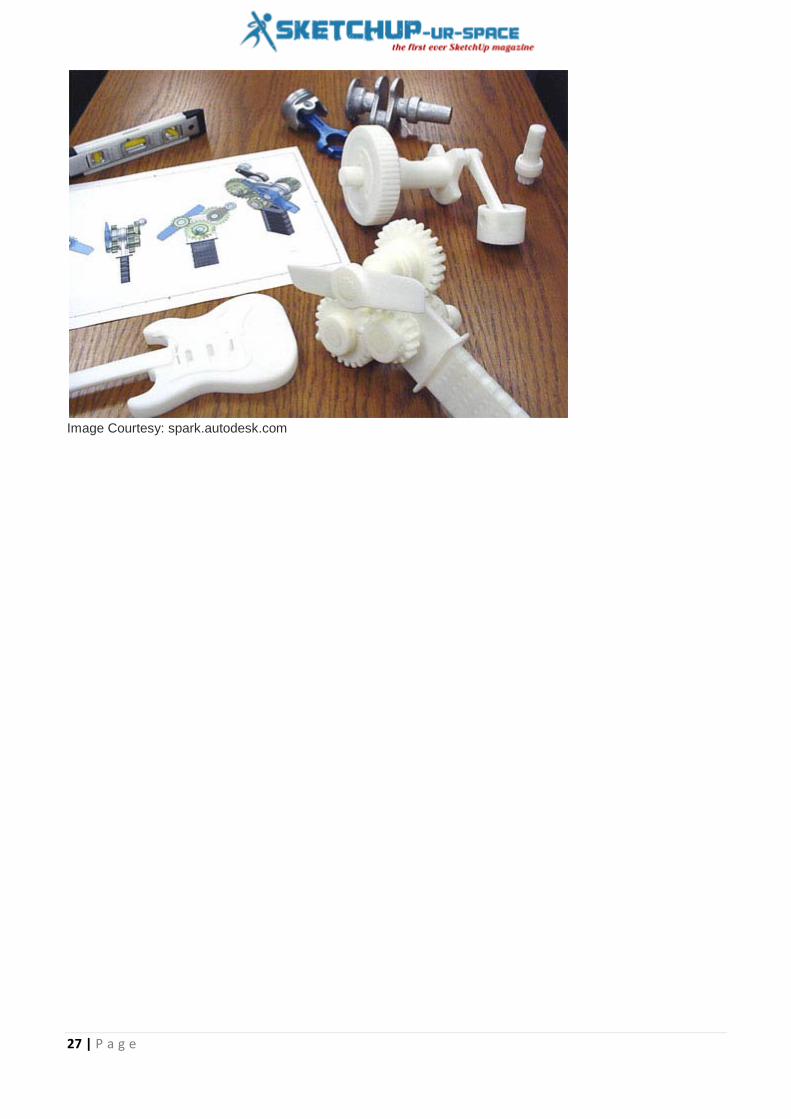
Autodesk and Microsoft collaborate to improve the future of Digital and Physical 3D Production
Rajib Dey : Editor-in-chief
In order to progress the future of digital and physical production, Autodesk has tied a knot with Microsoft Corp. to implant its 3d printing platform in Windows 10 as well as exchange and make use of information from its 3d modeling software into Microsoft’s mixed reality atmosphere, Microsoft HoloLens.
Digital models created with Autodesk Maya or Fusion 360 can be presented in the mixed reality atmosphere empowered by HoloLens.
This feature will be very useful for game developers and filmmakers to enhance the formation of a new generation of entertainment experiences. The designers and engineers will be able to view a full scale model digitally througout the upfront design stage of product development and reduce the time and cost necessary for physical prototypes prior to fabrication.
In near future, designers and engineers will get the ability to generate 3D models with their own conception through Autodesk software, like Fusion 360, view the models with HoloLens, and make them 3d printable on Spark supported printers.
Image Courtesy: 3dprintingindustry.com
Autodesk will implant its Spark 3D printing software platform in Windows 10 facilitating the windows users to make the best use of superior 3d printing application that rationalize the additive manufacturing method for a diversified software, material, and printer choices.
In order to expand the reach and development of the 3D printing industry, Autodesk will arrange the Spark APIs accessible for free to the Microsoft developer community to build upon.
Besides, Autodesk will also connect with Microsoft as a founding member of a 3D Manufacturing Format (3MF) association to produce and support a conventional 3D interchange and printing format
Microsoft and its global community of developers make it possible for all the consumers to deal with the complications of 3d design & printing.
27 | P a g e
Image Courtesy: spark.autodesk.com

28 | P a g e
How to transform your 2d design into 3d model with sketchup
Debamoy Ghosh
EagleUp is way uncomplicated and intuitive while using with the version 4. Here is helpful tutorial for our readers where we’ll show you the steps from 2D Design to an enclosed 3D model.
https://youtu.be/mQjm_zomfA8
Preparation: Now open the project with Eagle as usual. But before start, please make sure that your board has a closed line on layer 20 (Dimensions). The line or contour can be rectangle, or a complex polygon with round edges. But the circular contour does not work here. The reason is round contour has no edge. Now, set the width of the outline to zero so it’s as thin as possible. The board gave the tutorial -- ready to use. No other action needed.
Export from Eagle
• tPlace layer for the silk screen.
: It is a demo project with a layout and corresponding schematics. Please believe this only as a material for modelling. The preliminary thought was to make a simple 4-bit meter for analog signal. As a circuit it probably would not work!
Run the ULP “eagleUp_export.ulp”. Click on File / Run / eagleUp_export.ulp.
A window with a range of settings will come into view. Here you can put the colour of your board, the type of plating. The images will look way good with the 1200 dpi resolution. But the model will get heavier and slower, so you should use it for small boards only. 600 dpi is ok most of the time and has sufficient details. If you have a very big board or want a quick foretaste, you can use the 300 dpi but the excellence of the texts will be lower.
The findings are:
• tPlace + tNames if you have placed the designators correctly.
If you have a big board and just want a speedy preview of the board and components you can select the ‘no image’ option. It omits all the steps related to image making so it is much faster.
If you want to attempt differently color sets for your board, attempt the custom solder mask color. Then the pop-up will prompt two hexadecimal colors: one for the mask over copper (usually lighter) and one for mask over epoxy (darker). You can discover a color generator here.

29 | P a g e
Image Courtesy: eagleup.wordpress.com
Now Press OK to start on the export. It should take just a few seconds, and then you are back to your design. Users of older versions of Eagle (before 5.11) might see pop-ups requesting for overwriting of the image files.
The export script writes in the folder of your design a *.eup file with the entire particulars of your board: shape, thickness, position of the packages, and exports some images of the copper, silk and masks. These images will be mixed to make a sensible view of the PCB. You can run the export script as many times as you want with diverse settings to observe their effects. After a successful export you will observe a pop-up. If a new version of eagleUp is accessible you will get a notification as well.
Image Courtesy: eagleup.wordpress.com

30 | P a g e
Import in Sketchup
Image Courtesy: eagleup.wordpress.com
Now browse to your project directory and select the eup file earlier generated. You will watch the several terminal pop-ups and vanish during the creation of the PCB images. This step can take quite a few minutes with a big design on a slow computer.
After a few seconds you will see a pop-up saying:
: Now Open Sketchup. If asked, set the template to engineering in meters. It is suitable to sketch. Now enter the dimensions in meters instead of millimeters to get smaller details. You can delete any object included in the template.
Now, click on the Plugins menu, then import design from Eagle.
“Eagle'up import completed Missing packages: 1X02
Image Courtesy: eagleup.wordpress.com
The import is completed. There was no model for the pinheads so it is listed as missing.”
The import is completed. There was no model for the pinheads so it is listed as missing.
Note: if you are experiencing issues with the import in Sketchup, enable the ruby console in Window / Ruby console before running the plugin. This will give useful information.
A nice model of your earlier 2D design. But will it fit in an enclosure? No project is finished before being in a nice enclosure, right ?
Further integration: Use the measurements tools of Sketchup to get an idea of the dimensions of your project:

31 | P a g e
Image Courtesy: eagleup.wordpress.com
Always Rememorizes the unit is millimeter (mm) and not meter. Well it seems that Sparkfun Soapbox could be a match for our project.
From the datasheet provided you can attempt to model the enclosure. To save some time I have built-in this enclosure in the models. So you just have to click on File / import. Browse to your /models directory and select Soapbox.skp
You can turn around and translate the half-shell below your board to check the fitting. At this point you will usually notice clash and collisions.
Image Courtesy: eagleup.wordpress.com
You can control the board and the enclosure, check for the rising points, attachment, before having the real board or even acquire the enclosed space. CAD saves time, money and a lot of effort!
You may have observed that the Led pins were quite long. That’s because we have not yet cut them to the correct length. Let’s close the enclosure and check the length required to have the Leds noticeable from the outside.

32 | P a g e
The simplest is to copy the half-shelf with the rotate function. Press Control once and it will rotate+copy. Since the shell is regular you can use the middle point of the small side like shown below. Much faster than trying to add a new example and try to align it by hand.
Image Courtesy: eagleup.wordpress.com
With the top shell in place, select it and conceal or hide it (contextual menu). You can un-hide it at any time with edit / un-hide all.
Now select the four Leds, and move them up (along the blue axis).
Image Courtesy: eagleup.wordpress.com
Unhide all, and check if the Leds are noticeable above the enclosure. Repeat until you like the position of the Leds. For a final check you can relate a translucent material to the top shell. I use Translucent Glass Block Dark. Everything seems all right inside. You can now take steps of the location of the Leds, so you know where to drill the enclosure.

33 | P a g e
Image Courtesy: eagleup.wordpress.com
This project is not ended. You can finish the model by adding some correct connectors for the input signal and for the battery, and an On/Off switch. Maybe a larger field will be necessary after all. The tutorial display you the reimbursement of a 3D modelling of your electronic layout. Please ask in the comments if you need more detailed step.
Ref: eagleup.wordpress.com

34 | P a g e
Using the material database in Sketchup
Debamoy Ghosh
The tutorial would cover up the process that how to download and use materials from the online material database folder using the SkIndigo exporter for Sketchup.
The Indigo Material Database can be spotted at www.indigorenderer.com/materials
Two ways are existed to use materials from the online database in SketchUp/SkIndigo: loading straightway into SketchUp, and outwardly linking to downloaded materials. We'll cover both options in series, starting with the simpler direct introduce method.
Importing directly into SketchUp:-
1. Creation of a new Sketchup material
Image Courtesy: indigorenderer.com
: Now let's start by opening SketchUp and making a simple thing to apply the material to (in this case a cube). We'll also want to make a new SketchUp material (via Window menu -> Materials -> Create Material) to hold our Indigo material, and apply it to the newly shaped cube.
2. Opening the SkIndigo online material browser: Having shaped an easy object and applied a new material to it, from the "Plugins" menu, under the "SkIndigo" sub-menu, select "Material Editor":-

35 | P a g e
Image Courtesy: indigorenderer.com
This opens the SkIndigo material editor window. At the top of the material editor window is a "Search" button, click this to open the material database folder window in SkIndigo:
Image Courtesy: indigorenderer.com
3. Downloading and applying a material: The material database folder browser window will open unlock, permitting you to search for materials by keywords or name. By default the most lately materials presented will appear at the top:

36 | P a g e
Image Courtesy: indigorenderer.com
If we favor a material and double click it, SkIndigo will ask if you'd like to load it into the present selected material; click "Yes", or else it will want to save the downloaded material to disk.
The downloaded material should now be loaded into the SketchUp material and applied to your object, ready for rendering with Indigo:
Image Courtesy: indigorenderer.com
Alternative method: Linked IGM
It is however possible, that the material cannot be presented correctly within SketchUp, since it is not a physically-based renderer. Here, SketchUp will present a warning dialog suggestive of it be used as a "linked" material:

37 | P a g e
Image Courtesy: indigorenderer.com
Linking a downloaded material
Image Courtesy: indigorenderer.com
Click the "...” button next to the "IGM" field, and select a downloaded IGM or PIGM file. This will link the downloaded material to the SketchUp material so that when Indigo renders the scene, it will use the linked material.
Since the material cannot be represented properly in SketchUp, SkIndigo will prompt you for a texture to use for the material in the SketchUp viewport.
: To do this, we select the material in the SkIndigo material editor, and set its Material Type to "Linked IGM":

38 | P a g e
This is so you can effortlessly recognize the linked material, however it is optional:
Image Courtesy: indigorenderer.com
Reference:- www.indigorenderer.com

39 | P a g e
Some useful sketchup tips to create a digital floorplan with sketchup
Rajib Dey : Editor-in-chief
In order to digitally sketch any floor plan with sketchup, one should abide by the following procedures:-
Download and set up sketchup. After opening sketchup, opt for Plan View - Feet and Inches to assign the styles to drawing.
After that, visit View ---> Tool Palettes ---> Large Tool Set to avail all the toolset.
It is suggested that you should sketch the floorplan on the basis of a rough hand-sketch of your space and measurements of the length of all the walls. Ensure the position of your doorways as well as the lengths of all the walls. While gauging a whole apartment, you don’t have to contain wall thicknesses and other complicated details.
The following toolset are useful to draw any digital floor plan with sketchup :-
Orbit: Select this tool and then pull the cursor in the drawing area to rotate in 3D.
Zoom: Select this tool and then drag your cursor to position your view nearer to or further away from the drawing space.
Pan: Select this icon and then pull the cursor across the screen to shift to other areas of the drawing space.
Quadrant
Image Courtesy: apartmenttherapy.com
: In order to generate a floor plan, utilize the quadrant located at upper right corner of the drawing space. Pan to fill up the screen. In this quadratic plane area there are coordinates having positive numbers. For sketching perfect lines, just start the lower-left corner of your drawing where the axes meet at (0,0).
Line: In order to turn on the line tool, just click on the pencil tool. To sketch a line, click anywhere (at the origin). Then, shift the cursor equivalent to the X or Y axis. Put the desirable length of the line with keyboard (i.e. 10' 4

40 | P a g e
3/16"), and press enter. A line of the desirable length will be formed and the cursor will be set to the new endpoint. Apply identical procedure again to generate another line that starts with the endpoint of the first line.
Erase: In order to sketch doorways, just draw them with their individual lines with endpoints. After the drawing is completed, return back and remove the doorway segments to indicate that there exists passage in those areas. Use the erase tool, then select the part to be deleted.
Tips and Tricks
Image Courtesy: apartmenttherapy.com
For any error, at the time of sketching the figure, you should not start afresh from the beginning. Visit Edit ---> Undo Draw Line to back off a step. Now, just click on the preferred point from where the drawing will be started again.
: The program will help to notify you when you've come to the endpoint of another line. While sketching connected lines, ensure that you select only on these called-out green endpoints once the program "snaps to" them. The midpoint of a line can be detected by hovering across that fairly accurate location and look for a blue dot coming out on your screen.
Dimension: The dimensioning tool can be applied to mark the lengths of the lines already sketched. Click on either edge, or the two endpoints of a line, then drag the cursor exterior area. The dimension line will pass through as far as it is arranged on the position selected by you. Click to save.
Text: Select the text tool, then click anywhere on the page to position your text for writing. A box will be visible where you can start typing. This process is useful to label the rooms shown in the floor plan.
Save: After completing all the processes, go to File ---> Export ---> 2D Graphic to save the plan as a regular image file that can be used in Photoshop.

41 | P a g e
Image Courtesy: woodworkingpdf.co

42 | P a g e
Learn to produce a contoured block from a 2d contour plan with PlusSpec
Rajib Dey : Editor-in-chief
PlusSpec, is based on RubySketch’s 3000-plus individual models. PlusSpec facilitates the architects to search for and pick manufacturers’ own products at any phase of design instead of generic products.
PlusSpec performs within Sketchup by applying free flow design aptitudes whereas initiating new parametric functionality for sketching, editing and examining the structure, the geometry and the specification of the design at initial phase.
In the following tutorial, Andrew Dwight, founder & director of RubySketch, teaches you how to generate a contoured block out of a 2D contour plan as well as import a DWG or DXF and purge layers to simplify the contour plan. Once the video will be finished, you can learn how to produce a 3d model with your terrain.
https://youtu.be/1ykadGpBsRQ

43 | P a g e
An Important Association in 3D Printing to Creative Student, Formlabs Partners met Royal College of Art
Debamoy Ghosh
The stories which are my personal favorite, that are included in the 3D printing space are the ones that focus on mainly showcasing the technology to the students all over the world. These include our future manufacturers, leaders, engineers and creators. All of them will be there for us even when we would become old, as they are the people who will enhance the technology so that that we can live a better lifestyle and raise the standards of our living. Thus, from this it has been concluded by me and several researchers as well that here 3D printing has a vital role to play.
Image Courtesy: 3dprint.com
Here thus arises the question that why not to provide the students with all the essential tools that are needed to succeed in their future environment?
Formlabs, the creator of the Form 1+3D printer gets all this as done by the Royal College of Art in London. These two parties recently came into collaboration so as to host a word class research design course that deals with the future scope of desktop manufacturing. The course deals with how the process of the 3D printing can direct the industrial design landscape to head into the future.

44 | P a g e
Image Courtesy: 3dprint.com
Moreover, the students were also able to learn and experience 3D printing as a part of the Benchtop Factory program, as it was named.
The program was lead by the RCA Senior Tutor, James Tooze and also Formlabs designer, Yoav Reches. This program was done so as to let students to create products which could easily be 3D printed on a Form 1+3D printer.
The students came up with some fantastic and innovative concepts which will be displayed at Victoria and Albert Museum on March 28, 2015.
“We have created Formabs for engineers and designers to come up with new creative ideas” as explained by Max Lobovsky, Formlabs co-founder.
“We are trying to realize and understand the concept that how 3D printing will change the process of how we manufacture or make. Thus, it will be inspiring for all of us to work with these creative minded students who will explore new horizons on the Form1+”

45 | P a g e
Image Courtesy: 3dprint.com
Some of the great creations included:
• The need to remember was removed by Thomas Leech, Joshua Browne, Axel Bluhme, and Yun-Pei hsiung. Called as the Formkey, this is basically a 3D printed object which is the main physical embodiment of the online passwords of your’s. it helps you to get access to your accounts using just a simple swipe of the ‘Formkey’ in front of the webcam.
• Impression of the memory by Ivie Egonmwan, Cle Jentsch, Fiona O’Leary, and Tomomi Ogata- created aftermath on consideration for the Japanese earthquake. These students realized that the people come back to their ruined homes only in order to salvage whatever they can find. Howver, all these destroyed possessions often bring new meaning to their life and also develops new representation. The project thus, lead to the development of a new pattern making model, developed from these found the possession fragments.
• The Factory by Vaclav Mlynar and Pinja Maria Piira- The Factory manufactures custom light fittings by the help of a analogue material manipulation process and the parametric 3D models that are then generated in the software modeling and then are ultimately 3D printed on demand.
• The Growing Lab by Alex Loudon, Micaella Pedros, and Cristian Ferrara- this is a great experimental factory which prints the growing vessels that evolve with the plants.
• All these creations show that when 3D printing is provided to the students, their ideas can be then into practical implication. This reality will change the world someday.
• “The spread of ideas really impressed me,” as said by Dr. Sharon Baurley, Head of the Programme, Design Products at the RCA.
• “The discussion was to challenge the students to view the future scope of the benchtop manufacturing scenarios, and also thinking about the social-cultural, technological as well as the political changes to the concept of the manufacturing.”
• What you think Formlabs and RCA did to bring the 3D printing into the colleges for the students so as to understand the potential it provides with?
• Discuss all this in the Formlabs/RCA collaboration forum thread on 3DPB.com.
https://youtu.be/K_l2_gE2YII

46 | P a g e
Image Courtesy: 3dprint.com
Ref: 3dprint.com

47 | P a g e
The Common Problems of 3D Printing and Solutions
Debamoy Ghosh
The problem with 3D printing is here now to be discussed.
There are several of things that are awesome about 3D printing. It gives us the potentiality to hold any level of complication. It ensures pinpoint accuracy. The things we can make are limited only by our thought. And it transported the promise of mass customization.
But I just don’t think it’s quite right. This technology was made-up to for bring revolutionary change in manufacturing. Put ingenuity and creativity in everyone’s hands. Interrupt the production model and a printer in every home.
Image Courtesy: manufacturing.net
Most people are still on the left side of the “hype curve,” on the peak of inflated hope, headed for the disappointment.
Jeff Kowalski, Chief Technology Officer, Autodesk said, he hasn’t given up, though. He continues trying keeping the promise, but released needs to start pushing past the promise stage for 3D printing to descend on the ground. To try and centering the problem, here are the top five lamentation with the current state of 3D printing. This blog originally appeared on Line/Shape/Space.
Image Courtesy: manufacturing.net

48 | P a g e
1. Output/Quality: This is the most basic thing, but there are many quality-related troubles with 3D printing today:
2. Fragile, delaminated FDM (fused deposition modeling) parts
3. Low-resolution output
4. Materials
• Why are 3D printers transparent?
: Now, to be fair, the materials are defined by what can be extruded, squirted, or melted, but this is not based on their application or final use. And even though there are some instances of multi-materials, it’s characteristically only two at a time.
But Kowalski don’t want to limit the imagination. He wants a printer that enables materials that didn’t exist outside of the printer. He wants one that makes metal alloys in the box.
Let me give you an example here. Which will either crystallize the problem or make you wonder how old Jeff Kowalski is: Remember Shrinky Dinks? You’d draw these designs, put them in the oven, reduce in size them, and then . . . understand the result wasn’t really worth having.
But here’s the point: Kowalski said, need to shift the emphasis in 3D printing from “Look, I made something!” to “Look what I made!” It has to be repetitive, high quality, using great materials, and producible in no other way.
The Printing Process Is Unreliable: The complicatedness of just getting the method to work is often intimidating, and it involves too much fraud with formats, parameters as well as mechanical modification.
You all know the joke by now:
• So you can watch your build fail! • We can see what’s going on, but mostly it’s so we can interfere when the procedure breaks down.
It’s to the point where people put in cameras to watch their printers! Can you envisage standing there and staring at a 2D printer to confirm it was behaving properly? Of course it is not. It is time to shift from the fascination with 3D printers and 3D printing and focus on what is being 3D printed. Kowalski said: “Who cares if I have a great 3D printer, and I’m having a great time 3D printing? What I want is the output.”
Image Courtesy: manufacturing.net
Jeff Kowalski, actually look forward to the day when 3D printers are not transparent, but the path from design to fabrication is clear. When the whole procedure is so reliable and high quality that 3D printing experiences the wonderful fate of any victorious technology: ubiquity and invisibility. A boring, black box.

49 | P a g e
On the whole, the goal should be to move to “one-click-print” dependability. To get there, what’s needed is the equivalent of PostScript and the LaserWriter, which were the catalysts for dependable desktop publishing. That’s what it’s going to take to get some real traction on this “revolution.”
The Target: It’s Wrong: The fourth lamentation is that people have been aiming at the wrong target with their 3D-printing efforts.
They’ve been happy creating prototypes, replacement parts, and trinkets; but what they should be focused on is final parts and creating novel solutions to higher-level problems.
In order to reach this new goal, it’s vital to look at 3D printing holistically, through four different features of additive manufacturing:
• parts, • system, • materials, and • process.
In other built-up processes, you could divide these four ideas and optimize each separately. But in 3D printing, they all come together because they all influence each other. The best way to achieve assembly function is through materials. Springs, levers, hinges, and dampers can be achieved, not just via individual parts, but also through intelligent in-process materials. Understanding the relationship between interacting elements is key.
Image Courtesy: manufacturing.net
The Market: It’s Prematurely Mature: Jeff Kowalski believes, last 3D-printing lamentation is that 3D-printer manufacturers seem to be hastily solidifying standards and stifling innovation. Today, the 3D-printing market is still “prematurely mature.”
Manufacturers are unluckily mistaking that smaller, earlier chasm for the bigger one ahead. Customers are the supportive, not the majority. Yet manufacturers are using business models meant to optimize later phases as if there were already a printer in every home.
But that’s passionate thing, because this is still the first phase, where open innovation should still be major. Instead, you see manufacturers put ID chips in material cartridges, so they can’t be refilled or sourced to a different place.
Doing that gets you enthralled with material sales, and then you start doing dumb things like overprinting support materials, as opposed to addressing the real customer need, which is that they don’t want hold materials at all!
Thinking like this brings you to a stalemate condition because you put the business ahead of the customer. Everybody must agree that the industry is not done any innovation yet.

50 | P a g e
So here are Jeff Kowalski’s five lamentations and their potential cures summed into one sentence: Designers require solving problems with new solutions, less effort, more results, greater expression, increased reliably and confidence, and good quality.
Reference:- www.manufacturing.net

51 | P a g e
Trimble Expands the Construction Modeling Capabilities to HVAC Market
Debamoy Ghosh
Trimble has announced that it is assisting the new construction modeling workflows with the grater integration between Bentley Systems' AECOsim Building Designer software and Trimble's Vulcan sheet metal cutting software for the HVAC (heating, ventilation and air conditioning) market.
The new workflow integration permits design models to be shared at ease, save and securely and precisely in an exact manner. This very action extends the companies' ongoing partnership around “Construction Modeling” and boost up information mobility—which includes a target to influence Bentley i-models when Trimble and Bentley solutions are used together in project delivery.
Trimble is working with technologies to create field and mobile workers in businesses and government considerably more productive. Solutions are concentrated on applications requiring position or location—including surveying, agriculture fleet and asset management, public safety as well as mapping. It was founded in 1978; Trimble’s headquartered is situated in Sunnyvale, Calif.
Vulcan is a sheet metal cutting software solution for HVAC contractors, design/build firms and duct manufacturers, who rely on the software to boost shop productivity, decrees waste and improve their bottom lines. AECOsim Building Designer is Bentley's software for teams involved in the design, analysis, contracting, documentation and visualization of buildings.
The platform leverages i-models for the open exchange of project information so that team members may share and interrelate with complex project data and across product lines and technology platforms. By expanding Trimble and Bentley's existing i-model integrations to Vulcan, users can straightway send out design drawings to sheet metal fabrication, which can decrease errors and rework, and in the end save time and costs.
Image Courtesy: mep.trimble.com
“Sheet metal cutting and fabrication require the utmost precision to ensure the finished product will meet design specifications exactly, but the design-to-fabrication gap is where errors are most likely to occur. Bentley's i-models ease data-sharing and improve accuracy so that our customers can feel confident that the fabricated product matches the design spot-on.” said Pat Bohle, general manager of the MEP Division within Trimble Buildings.
“Trimble and Bentley share the goal of improving productivity and accuracy across construction processes, so we're pleased that our collaboration continues to deliver significant and tangible benefits to the industry. We look forward to combining our efforts in supporting construction modeling workflows for all disciplines," said Harry Vitelli, Bentley Systems senior vice president, construction and field.
Availability: The brand new means will be fitted into Vulcan 2015 version 2, which is predictable to be available in the 2nd quarter of 2015 through Trimble Buildings' MEP Division. More information is available at: mep.trimble.com/products/fabrication/vulcan

52 | P a g e
Bentley's Software Solutions: Bentley Systems and its wide-ranging software solutions for developing the the design, construction and operations of infrastructure, you should visit:www.bentley.com/en-US
Trimble Buildings is itself a renowned one. This building is a Trimble's Engineering and Construction section, which is a world leader in solutions that optimize the complete Design-Build-Operate (DBO) lifecycle of buildings. Incorporating the Trimble Connect partnership platform and spanning top brands such as SketchUp, Proliance, Vico Office, WinEst, Tekla, Gehry Technologies, Accubid, Manhattan Software. Information on Trimble Buildings' DBO portfolio is available at: buildings.trimble.com
Image Courtesy: mep.trimble.com

53 | P a g e
Magazine Details – The Creative team of Sketchup-ur-Space
Started in September 2010, Sketchup ur Space (SuS) was the first online magazine devoted to SketchUp, that unique, innovative 3D design tool from Google. It holistically covers features, events, news, updates, reviews and many tips and tricks.
Rajib Dey: [email protected]
Rajib, the editor-in-chief of SketchUp ur Space magazine is the main writer. He is responsible to write the cover story, blog and many other columns. Along with it, He is creating a liaison between the writers and the readers.
Manoj Kumar Singh: [email protected]
Manoj is enthusiastic helps to put the content of the SketchUp up Space magazine in the html version. Manoj is the html developer who beautifully creates each and every edition with care along with the PDF version.
Abhishek Mondal: [email protected]
Abhishek is the designer-in-chief of this magazine with the help of his creativity Sketchup ur Space has gotten a classy as well as trendy look...
Debamoy Ghosh: [email protected]
Pouring the confidence to budding 3D modelers is a challenge, which makes them believe that they can create a universe. I try to bring exciting stories that not only riveting read but put them the right technical path. After all, every right action needs believe and determination for fulfillment.