1 2h. s. lee and 2y. b. kim, 1e. kim, 1i. w. lee, 1y. s
TRANSCRIPT
Development of Prefabricated Concrete Slab Track Systems and Trial Installation on Revenue Line
1S. Y. Jang, 2H. S. Lee and 2Y. B. Kim, 1E. Kim, 1I. W. Lee, 1Y. S. Kang Korea Railroad Research Institute, Uiwang, South Korea; Sampyo E&C, Seoul, South Korea
Abstract
Recently the development and application of the slab track is increasing since the slab track is a strong alternative for the conventional ballasted track to curtail the track maintenance. Especially, the prefabricated slab track is taking notice because it is easy to install, and ensures high quality construction. In this study, presented are two designs of prefabricated slab track systems; one is designed for high-speed and heavy-axle load railway lines (Type A) and the other is for urban and conventional railway lines (Type B). The development processes – design, laboratory performance evaluation – of the proposed prefabricated slab track systems are highlighted and the trial installation of the systems on a revenue line and its results are presented and discussed herein.
Introduction
Conventional ballasted track requires continuous maintenance for keeping track alignment within severe tolerance limits for safety and ride comfort, and burdens on operating organizations become bigger and bigger. Hence, a strong demand for innovation of track structure has been raised. For one of remarkable alternatives, “slab track” has been proven to be almost maintenance free elsewhere for several decades [6,7,17], and thus it is expected to drastically curtail the track maintenance and to provide higher quality with lower LCC.
Cast-in-place concrete slab track, most-widely used type of slab track over the world, nevertheless, has been pointed out to have some shortcomings; 1) it is not easy to ensure the quality of concrete slab, 2) due to curing time for concrete, the speed of track installation is often limited, and 3) in underground or in tunnel section, during concreting, exhaust fumes discharged from ready-mixed concrete vehicles severely threats the health of workers. Prefabricated slab track, therefore, is preferable in theses aspects. Then in Germany, China, Italy and Spain as well as in Japan, the prefabricated slab track has been widely applied.
In this paper, the development processes of new prefabricated concrete slab track systems – design, performance evaluation in the laboratory and test installation on a revenue line are highlighted and the results are discussed.
System Outlines
Design requirements and concept of the prefabricated system Requirements for the prefabricated slab track systems can be summarized as follows: 1)
target track grade (train speed and axle loads), 2) safety, 3) serviceability, 4) installation efficiency, 5) maintainability, and 6) economical efficiency.
The design of the prefabricated track structure and its components were especially focused to achieve installation efficiency and maintainability while all the other requirements being observed.
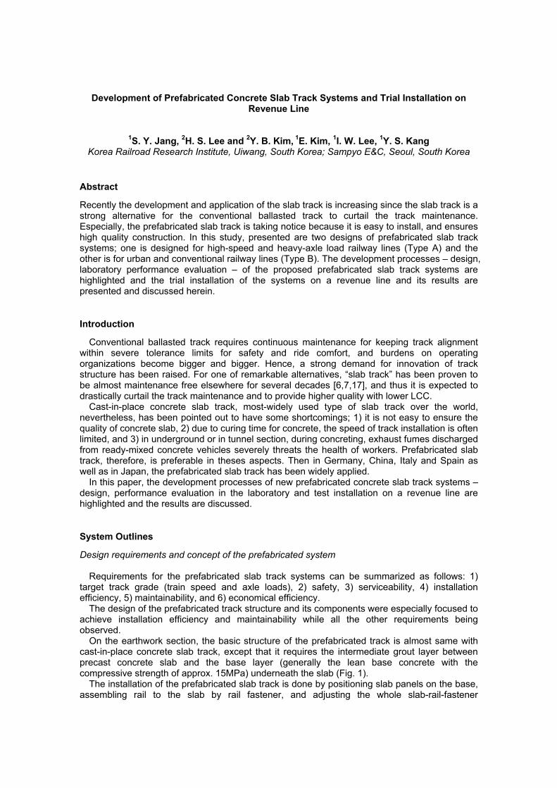
On the earthwork section, the basic structure of the prefabricated track is almost same with cast-in-place concrete slab track, except that it requires the intermediate grout layer between precast concrete slab and the base layer (generally the lean base concrete with the compressive strength of approx. 15MPa) underneath the slab (Fig. 1).
The installation of the prefabricated slab track is done by positioning slab panels on the base, assembling rail to the slab by rail fastener, and adjusting the whole slab-rail-fastener
assemblage. After that, grout is poured under the slab and the final adjustment is done. Thus, to increase the efficiency and speed of installation, required is under-pouring grout that can be poured quickly and precisely and can gain early age strength and volumetric stability.
When the adjustment of alignment is needed in service, small scale of adjustment can be done by the rail fastener, and larger scale of adjustment exceeding the adjustment limit of rail fastener can be done by the additional injection of grout. Also, it is possible to replace the slab panel itself and thus it is expected to obtain higher maintainability than the cast-in-place concrete slab track.
Fig.1: Prefabricated concrete slab track versus cast-in-place concrete slab track
Outline of track structure and its components
In the design, according to the target track grade, two types of prefabricated slab tracks have been proposed; one is designed for high-speed lines (Type A - design axle load of 250kN, max. train speed of 350km/h), and the other is for urban and conventional lines (Type B - design axle load of 180~220kN, max. train speed up to 200km/h).
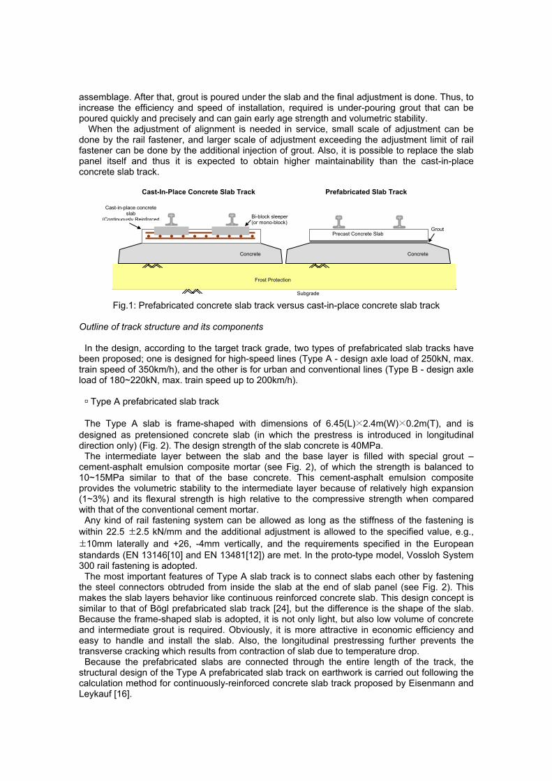
Type A prefabricated slab track
The Type A slab is frame-shaped with dimensions of 6.45(L)×2.4m(W)×0.2m(T), and is
designed as pretensioned concrete slab (in which the prestress is introduced in longitudinal direction only) (Fig. 2). The design strength of the slab concrete is 40MPa.
The intermediate layer between the slab and the base layer is filled with special grout – cement-asphalt emulsion composite mortar (see Fig. 2), of which the strength is balanced to 10~15MPa similar to that of the base concrete. This cement-asphalt emulsion composite provides the volumetric stability to the intermediate layer because of relatively high expansion (1~3%) and its flexural strength is high relative to the compressive strength when compared with that of the conventional cement mortar.
Any kind of rail fastening system can be allowed as long as the stiffness of the fastening is within 22.5 ±2.5 kN/mm and the additional adjustment is allowed to the specified value, e.g., ±10mm laterally and +26, -4mm vertically, and the requirements specified in the European standards (EN 13146[10] and EN 13481[12]) are met. In the proto-type model, Vossloh System 300 rail fastening is adopted.
The most important features of Type A slab track is to connect slabs each other by fastening the steel connectors obtruded from inside the slab at the end of slab panel (see Fig. 2). This makes the slab layers behavior like continuous reinforced concrete slab. This design concept is similar to that of Bögl prefabricated slab track [24], but the difference is the shape of the slab. Because the frame-shaped slab is adopted, it is not only light, but also low volume of concrete and intermediate grout is required. Obviously, it is more attractive in economic efficiency and easy to handle and install the slab. Also, the longitudinal prestressing further prevents the transverse cracking which results from contraction of slab due to temperature drop.
Because the prefabricated slabs are connected through the entire length of the track, the structural design of the Type A prefabricated slab track on earthwork is carried out following the calculation method for continuously-reinforced concrete slab track proposed by Eisenmann and Leykauf [16].
Prefabricated Slab Track Cast-In-Place Concrete Slab Track
Cast-in-place concrete slab
(Continuously Reinforced
Precast Concrete Slab Grout
Concrete
Bi-block sleeper (or mono-block)
Frost Protection
Subgrade
Concrete
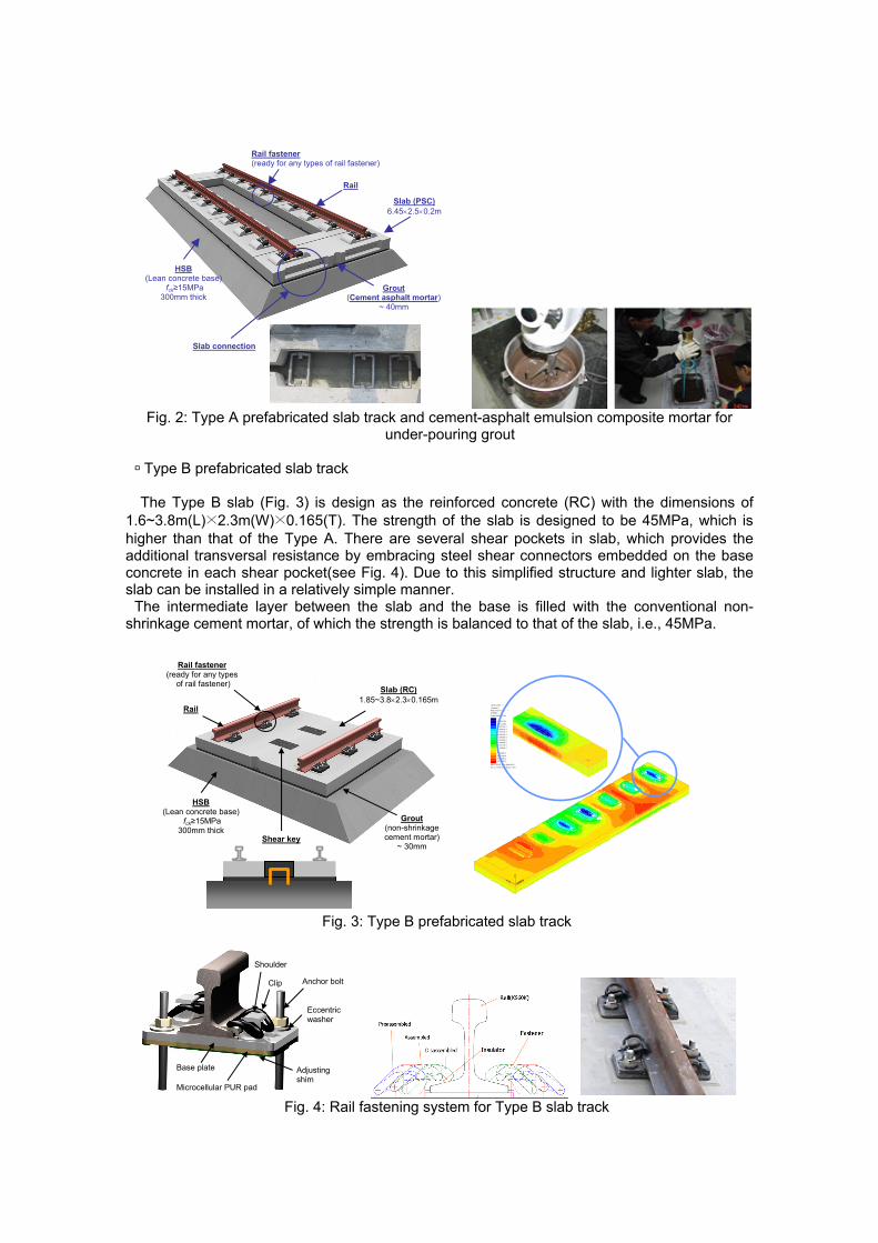
Fig. 2: Type A prefabricated slab track and cement-asphalt emulsion composite mortar for
under-pouring grout
Type B prefabricated slab track
The Type B slab (Fig. 3) is design as the reinforced concrete (RC) with the dimensions of 1.6~3.8m(L)×2.3m(W)×0.165(T). The strength of the slab is designed to be 45MPa, which is higher than that of the Type A. There are several shear pockets in slab, which provides the additional transversal resistance by embracing steel shear connectors embedded on the base concrete in each shear pocket(see Fig. 4). Due to this simplified structure and lighter slab, the slab can be installed in a relatively simple manner.
The intermediate layer between the slab and the base is filled with the conventional non-shrinkage cement mortar, of which the strength is balanced to that of the slab, i.e., 45MPa.
Fig. 3: Type B prefabricated slab track
Fig. 4: Rail fastening system for Type B slab track
HSB (Lean concrete base)
fck≥15MPa 300mm thick
Rail fastener (ready for any types
of rail fastener)
Grout (non-shrinkage cement mortar)
~ 30mm
Slab (RC)1.85~3.8×2.3×0.165m
Rail
Shear key
XY
Z
LOAD CASE = 1Loadcase 1RESULTS FILE = 1STRESS
CONTOURS OF SX
4.40343E-33.30258E-32.20172E-3
1.10086E-30-1.10086E-3
-2.20172E-3-3.30258E-3-4.40343E-3-5.50429E-3-6.60515E-3
-7.70601E-3-8.80687E-3-9.90773E-3-0.0110086
-0.0121094
Max 0.4437E-02 at Node 4341
Min -0.1318E-01 at Node 11201
Rail
Slab (PSC)6.45×2.5×0.2m
HSB (Lean concrete base)
fck≥15MPa 300mm thick
Rail fastener (ready for any types of rail fastener)
Grout (Cement asphalt mortar)
~ 40mm
Slab connection
Clip Anchor bolt
Eccentric washer
Base plate
Microcellular PUR pad
Adjusting shim
Shoulder
For the rail fastening, any kind of rail fastening system can be allowed, same with the Type A, as long as the requirements for the vertical stiffness (around 20kN/mm) and the adjustment and others specified in EN 13146[10] and EN 13481[12] are met. In the proto-type model, installed is a new rail fastening system developed by KRRI and SAMPYO which is unique in fastening the rail clip outwards from the side of rail (Fig. 4) to increase safety by preventing the fly out of the unfastened clip, and allows the pre-assembling and the adjustment of alignment up to ±13mm laterally and +26mm/-4mm vertically.
The Type B slab track is originally designed for the urban railway, and hence this structure is more appropriate in the tunnel and viaduct sections. On earthwork section, since the Type B slab is discontinuous, unlike the Type A, it is required to check if the thickness and the strength of the concrete base are enough at each slab joint.
Laboratory Test for Performance Evaluation
In the laboratory, the performance test for the slab track system and its components have been carried out. As the prefabricated track systems very similar to the Type A track had been already proved in operation in Germany [9], only tests for the slab panel and grouting material have been performed. However, for the Type B slab track, the mock-up fatigue test for the whole system assembly, the horizontal shear resistance test and tests for slab panel, grouting material and the fastening system have been carried out. The test methods are basically in accordance with European Standards and other national standards [13,18-23].
In the performance test of the Type A slab panel, to verify the lateral reinforcement design of the end part of the frame-shaped slab, the flexural test with a concentrated load on the rail seat and center section of the end part has been implemented. According to the test results, no visible cracks were observed up to 18.6kN·m at rail seat section and 15.7kN·m at center section which are the required flexural strength specified in KRS TR 0008-06 [18].
For the Type B slab, the flexural test according to EN 13230-1~3 has been carried out. The results shows that no remarkable cracks did not appear up to the design flexural moment Md (19.6kN m longitudinal direction and 9.6kN m in lateral direction), and the crack widths did not exceed 0.05mm up to at least 3.9×Md under static loads and 5.5×Md under dynamic loads. Also, the moment at fracture was recorded much higher.
0
2
4
6
8
10
12
14
0 5 10 15 20 25 30
Age (days)
Stre
ngth
(MPa
)
3-10-A04 (Comp.) - Standard curing3-10-A04 (Comp.) - 45°C curing3-10-A04 (Flex.) - Standard curing3-10-A04 (Flex.) - 45°C curing
1.5
2
2.5
3
3.5
4
0 3 6 9 12 15 18 21 24 27 30Age (days)
Expa
nsio
n (%
)
3-10-A04
3hr
1day
60
70
80
90
100
110
0 50 100 150 200 250 300
Freezing-tahwing cycles
Rel
ativ
e el
astic
mod
uli o
f ela
stic
ity (M
Pa)
3-10-A163-10-A04
Fig. 5: Some test results of under-pouring grouts
Type of cement (ASTM)
(1=Type I, 3=Type 3)Asphalt emulsion-binder ratio (16=1.6, 12=1.2, 08=0.8, 04=0.4)
1-10-A16 Content of CSA admix. for increasing expansion (10=10%, 15=15% by binder weight)
The test results of the under-pouring grouts, cement-asphalt emulsion composite mortar and non-shrinkage cement mortar, exhibit that both grouting materials have enough strength and flowability to fill the intermediate layer. The cement-asphalt emulsion composite mortar has lower strength (10~15MPa) than the non-shrinkage cement mortar (over 45MPa), but higher flexural strength relative to the compressive strength (Fig. 5).
The fastening system used in the Type B proto-type model has been tested to evaluate the performance according to EN 13481-5 and EN 13146-1~7 and the results show that the performance of the fastening system is appropriate for application in practice [8,25].
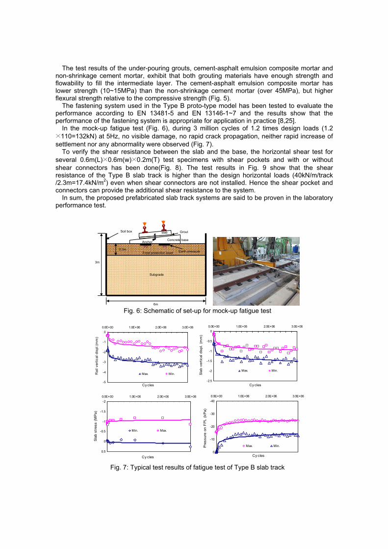
In the mock-up fatigue test (Fig. 6), during 3 million cycles of 1.2 times design loads (1.2 ×110=132kN) at 5Hz, no visible damage, no rapid crack propagation, neither rapid increase of settlement nor any abnormality were observed (Fig. 7).
To verify the shear resistance between the slab and the base, the horizontal shear test for several 0.6m(L)×0.6m(w)×0.2m(T) test specimens with shear pockets and with or without shear connectors has been done(Fig. 8). The test results in Fig. 9 show that the shear resistance of the Type B slab track is higher than the design horizontal loads (40kN/m/track /2.3m=17.4kN/m2) even when shear connectors are not installed. Hence the shear pocket and connectors can provide the additional shear resistance to the system.
In sum, the proposed prefabricated slab track systems are said to be proven in the laboratory performance test.
Fig. 6: Schematic of set-up for mock-up fatigue test
-5
-4
-3
-2
-1
00.0E+00 1.0E+06 2.0E+06 3.0E+06
Cy cles
Rai
l ver
tical
dis
pl.(
mm
)
Max. Min.
-2.5
-2
-1.5
-1
-0.5
00.0E+00 1.0E+06 2.0E+06 3.0E+06
Cy cles
Sla
b ve
rtic
al d
ispl
. (m
m)
Max. Min.
-2
-1.5
-1
-0.5
0
0.5
0.0E+00 1.0E+06 2.0E+06 3.0E+06
Cy cles
Sla
b st
ress
(M
Pa)
Min. Max.
-40
-30
-20
-10
0
0.0E+00 1.0E+06 2.0E+06 3.0E+06
Cy cles
Pre
ssur
e on
FP
L (k
Pa)
Max. Min.
Fig. 7: Typical test results of fatigue test of Type B slab track
slab
Concrete base Anchor
Grout
Frost protection layer
Subgrade
Soil box
0.3m
3m
Earth pressure
6m
P2 P1
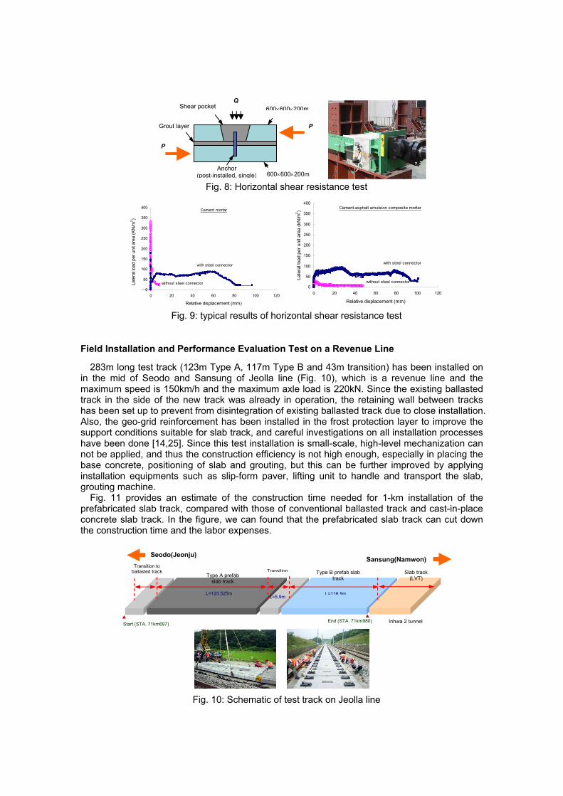
Fig. 8: Horizontal shear resistance test
0
50
100
150
200
250
300
350
400
0 20 40 60 80 100 120
Relative displacement (mm)
Late
ral lo
ad p
er u
nit a
rea
(KN
/m2 )
without steel connector
with steel connector
Cement mortar
0
50
100
150
200
250
300
350
400
0 20 40 60 80 100 120
Relative displacement (mm)La
tera
l loa
d pe
r uni
t are
a (k
N/m
2 )
with steel connector
without steel connector
Cement-asphalt emulsion composite mortar
Fig. 9: typical results of horizontal shear resistance test
Field Installation and Performance Evaluation Test on a Revenue Line
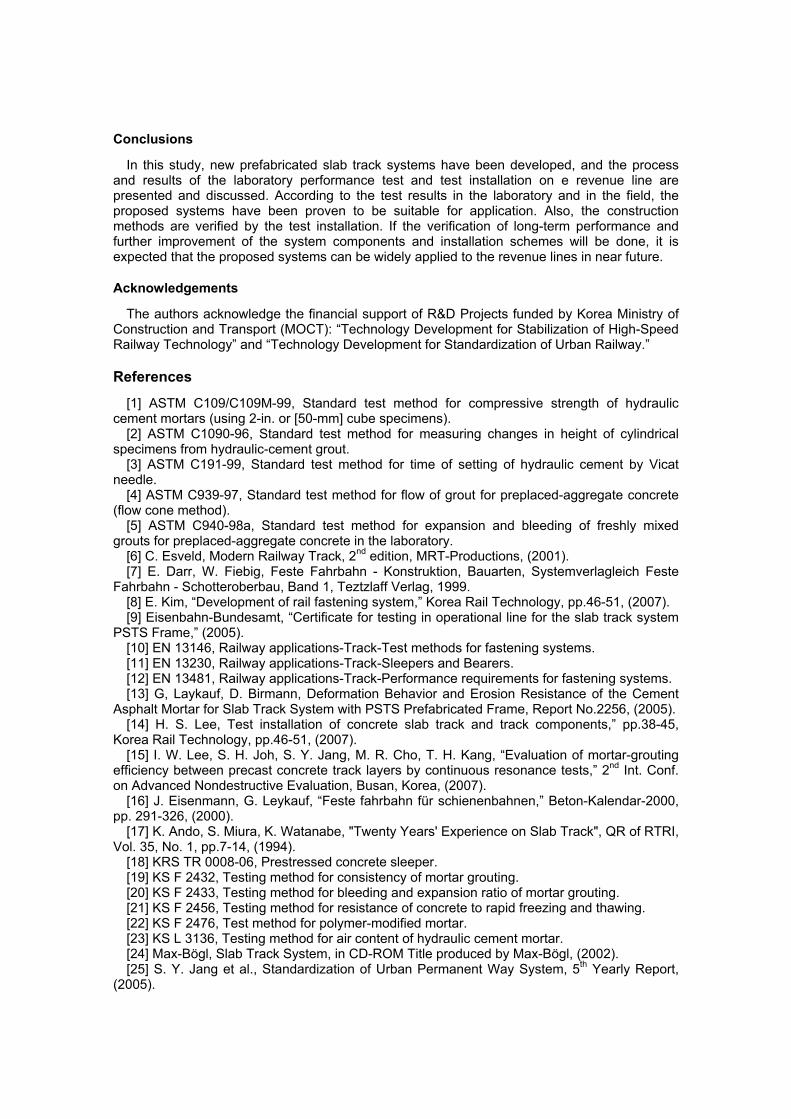
283m long test track (123m Type A, 117m Type B and 43m transition) has been installed on in the mid of Seodo and Sansung of Jeolla line (Fig. 10), which is a revenue line and the maximum speed is 150km/h and the maximum axle load is 220kN. Since the existing ballasted track in the side of the new track was already in operation, the retaining wall between tracks has been set up to prevent from disintegration of existing ballasted track due to close installation. Also, the geo-grid reinforcement has been installed in the frost protection layer to improve the support conditions suitable for slab track, and careful investigations on all installation processes have been done [14,25]. Since this test installation is small-scale, high-level mechanization can not be applied, and thus the construction efficiency is not high enough, especially in placing the base concrete, positioning of slab and grouting, but this can be further improved by applying installation equipments such as slip-form paver, lifting unit to handle and transport the slab, grouting machine.
Fig. 11 provides an estimate of the construction time needed for 1-km installation of the prefabricated slab track, compared with those of conventional ballasted track and cast-in-place concrete slab track. In the figure, we can found that the prefabricated slab track can cut down the construction time and the labor expenses.
Fig. 10: Schematic of test track on Jeolla line
600×600×200m
600×600×200mAnchor
(post-installed, single)
Grout layer
Shear pocket Q
P
P
Type A prefab slab track
Start (STA. 71km697) End (STA. 71km980)
L=123.525m
Seodo(Jeonju) Sansung(Namwon)
Transition
L=5.9m
Type B prefab slab track
L=116.9m
Slab track (LVT)
Inhwa 2 tunnel
Transition to ballasted track

After installation, the investigation of the track alignment and the performance tests and have been carried out. Fig. 12-13 shows some examples of the measured data on test track. It can be shown that the track irregularity gross for 1 year after installation is negligible (see Fig. 12), and wheel loads and displacements under train load of the track are within the design values (Fig. 13). Also, during 1 year monitoring period, no abnormal change of the response of the track were found.
0%
10%
20%
30%
40%
50%
60%
70%
80%
90%
100%
0 10 20 30 40 50 60 70 80 90
Time [days]
Wor
k pr
oces
s [%
]
C-I-P slab trackBallasted trackPrefab slab track
Survey
Placing(baseconcrete)
Transport of rail
Transport of sleeper
Assemblingrail and sleeper
Placing ballast
Raising sleeper
Adjustment/Tamping
Fininsh
Curing(base)
Transport of rail
Transport of sleeper
Assemblingrail and sleeper
Adjustment
Formw ork
Placing(track slab)
Curing(track slab)
FinishFinish
Rail installation
Curing(grout)
Placing(grout)
Preparationof grout
Transport ofslab panel
Positioningslab panel
Fig. 11: Construction time needed for 1-km installation
-10
-5
0
5
10
0 100 200 300 400 500 600 700Distance (from Inhwa 2 tunnel) (m)
Ver
tical
alig
nmen
t dev
iatio
n(1
0m c
hord
)(mm
)
2006-11-17 2007-02-14 2007-04-172007-08-01 2007-08-17(after tamping)
prefab slab track ballasted tracktransition
-10
-5
0
5
10
0 100 200 300 400 500 600 700Distance (from Inhwa 2 tunnel) (m)
Hor
izon
tal a
ignm
ent d
evia
tion
(10m
cho
rd)(m
m)
2006-11-17 2007-02-14 2007-04-172007-08-01 2007-08-17(after tamping)
prefab slab track ballasted tracktransition
Fig. 12: Measured track alignment
-140
-120
-100
-80
-60
-40
-20
0
201 2 3 4 5 6 7 8
Time (sec)
Verti
cal w
heel
load
(kN
)
point 1point 2
-2
-1.5
-1
-0.5
0
0.5
11 2 3 4 5 6 7 8
Time (sec)
Ver
tical
rail
defle
ctio
n (m
m)
point 1point 2
Fig. 13: Typical results of measured data during train passage
Conclusions
In this study, new prefabricated slab track systems have been developed, and the process and results of the laboratory performance test and test installation on e revenue line are presented and discussed. According to the test results in the laboratory and in the field, the proposed systems have been proven to be suitable for application. Also, the construction methods are verified by the test installation. If the verification of long-term performance and further improvement of the system components and installation schemes will be done, it is expected that the proposed systems can be widely applied to the revenue lines in near future.
Acknowledgements
The authors acknowledge the financial support of R&D Projects funded by Korea Ministry of Construction and Transport (MOCT): “Technology Development for Stabilization of High-Speed Railway Technology” and “Technology Development for Standardization of Urban Railway.”
References
[1] ASTM C109/C109M-99, Standard test method for compressive strength of hydraulic cement mortars (using 2-in. or [50-mm] cube specimens).
[2] ASTM C1090-96, Standard test method for measuring changes in height of cylindrical specimens from hydraulic-cement grout.
[3] ASTM C191-99, Standard test method for time of setting of hydraulic cement by Vicat needle.
[4] ASTM C939-97, Standard test method for flow of grout for preplaced-aggregate concrete (flow cone method).
[5] ASTM C940-98a, Standard test method for expansion and bleeding of freshly mixed grouts for preplaced-aggregate concrete in the laboratory.
[6] C. Esveld, Modern Railway Track, 2nd edition, MRT-Productions, (2001). [7] E. Darr, W. Fiebig, Feste Fahrbahn - Konstruktion, Bauarten, Systemverlagleich Feste
Fahrbahn - Schotteroberbau, Band 1, Teztzlaff Verlag, 1999. [8] E. Kim, “Development of rail fastening system,” Korea Rail Technology, pp.46-51, (2007). [9] Eisenbahn-Bundesamt, “Certificate for testing in operational line for the slab track system
PSTS Frame,” (2005). [10] EN 13146, Railway applications-Track-Test methods for fastening systems. [11] EN 13230, Railway applications-Track-Sleepers and Bearers. [12] EN 13481, Railway applications-Track-Performance requirements for fastening systems. [13] G, Laykauf, D. Birmann, Deformation Behavior and Erosion Resistance of the Cement
Asphalt Mortar for Slab Track System with PSTS Prefabricated Frame, Report No.2256, (2005). [14] H. S. Lee, Test installation of concrete slab track and track components,” pp.38-45,
Korea Rail Technology, pp.46-51, (2007). [15] I. W. Lee, S. H. Joh, S. Y. Jang, M. R. Cho, T. H. Kang, “Evaluation of mortar-grouting
efficiency between precast concrete track layers by continuous resonance tests,” 2nd Int. Conf. on Advanced Nondestructive Evaluation, Busan, Korea, (2007).
[16] J. Eisenmann, G. Leykauf, “Feste fahrbahn für schienenbahnen,” Beton-Kalendar-2000, pp. 291-326, (2000).
[17] K. Ando, S. Miura, K. Watanabe, "Twenty Years' Experience on Slab Track", QR of RTRI, Vol. 35, No. 1, pp.7-14, (1994).
[18] KRS TR 0008-06, Prestressed concrete sleeper. [19] KS F 2432, Testing method for consistency of mortar grouting. [20] KS F 2433, Testing method for bleeding and expansion ratio of mortar grouting. [21] KS F 2456, Testing method for resistance of concrete to rapid freezing and thawing. [22] KS F 2476, Test method for polymer-modified mortar. [23] KS L 3136, Testing method for air content of hydraulic cement mortar. [24] Max-Bögl, Slab Track System, in CD-ROM Title produced by Max-Bögl, (2002). [25] S. Y. Jang et al., Standardization of Urban Permanent Way System, 5th Yearly Report,
(2005).