1 2 group communication routing what is ip multicast ... · • the group management ... – to the...
TRANSCRIPT
1
1
LANCASTERLANCASTERUNIVERSITYUNIVERSITY
ComputingDepartment© Laurent Mathy
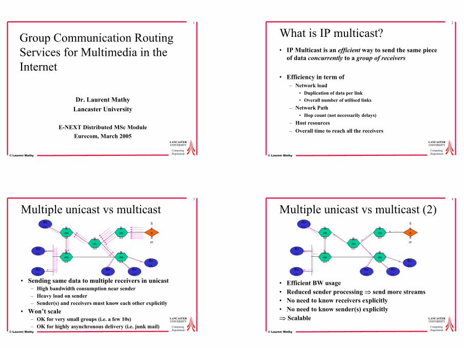
Group Communication Routing Services for Multimedia in the Internet
Dr. Laurent MathyLancaster University
E-NEXT Distributed MSc ModuleEurecom, March 2005
2
LANCASTERLANCASTERUNIVERSITYUNIVERSITY
ComputingDepartment© Laurent Mathy
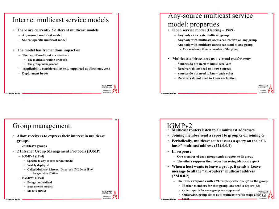
What is IP multicast?• IP Multicast is an efficient way to send the same piece
of data concurrently to a group of receivers
• Efficiency in term of– Network load
• Duplication of data per link• Overall number of utilised links
– Network Path• Hop count (not necessarily delays)
– Host resources– Overall time to reach all the receivers
3
LANCASTERLANCASTERUNIVERSITYUNIVERSITY
ComputingDepartment© Laurent Mathy
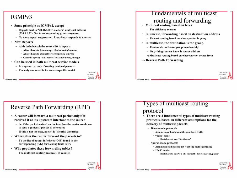
Multiple unicast vs multicast
• Sending same data to multiple receivers in unicast– High bandwidth consumption near sender– Heavy load on sender– Sender(s) and receivers must know each other explicitly
• Won’t scale– OK for very small groups (i.e. a few 10s)– OK for highly asynchronous delivery (i.e. junk mail)
Router
Router
Router
Router
Router
Sender
Recv.
Recv.
Recv.
Recv.
Recv.
Recv.
4
LANCASTERLANCASTERUNIVERSITYUNIVERSITY
ComputingDepartment© Laurent Mathy
Multiple unicast vs multicast (2)
• Efficient BW usage• Reduced sender processing ⇒ send more streams• No need to know receivers explicitly• No need to know sender(s) explicitly⇒ Scalable
Router
Router
Router
Router
Router
Sender
Recv.
Recv.
Recv.
Recv.
Recv.
Recv.

2
5
LANCASTERLANCASTERUNIVERSITYUNIVERSITY
ComputingDepartment© Laurent Mathy
IP multicast addresses: IPv4• Group of receivers identified by multicast address• IPv4
– Class D: 224.0.0.0-239.255.255.255 (~270 million addresses)
• Well-known address range: 224.0.0.0/24 (local link)• Transient addresses
– Global scope: 224.0.1.0-238.255.255.255– Limited scope: 239.0.0.0/8
• Site-local scope: 239.253.0.0/16• Organisation-local scope: 239.192.0.0/14
• RFC 3171
c1 1 1 0 Group identifier
6
LANCASTERLANCASTERUNIVERSITYUNIVERSITY
ComputingDepartment© Laurent Mathy
IPv4 multicast address scoping• TTL scoping: currently
– Configured threshold on router interfaces– Forwarding only if TTL packet >= TTL threshold– Error prone!– No overlapping zones
• Administrative scoping: near future– Zones can overlap– Multicast-scope Zone Announcement Protocol (MZAP)
• RFC 2776– Multicast Address Dynamic Client Allocation Protocol
• MADCAP scope nesting option: RFC 2907
7
LANCASTERLANCASTERUNIVERSITYUNIVERSITY
ComputingDepartment© Laurent Mathy
IP Multicast addresses: IPv6
• Range FF::0/11• flgs: 000b
– b = 0: permanent (well known) address– b = 1: transient address
• scop defines scope (4 bits)– 1 = node-local– 2 = link-local– 5 = site-local– 8 = organisation-local– E = global
• Many reserved addresses• See RFC 2373 and RFC 2375
11111111 flgs scop Group identifier
8
LANCASTERLANCASTERUNIVERSITYUNIVERSITY
ComputingDepartment© Laurent Mathy
Components of the IP multicast architecture• Multicast service models
• Group management protocols (network edge)
• Multicast routing protocols (inside network)
3
9
LANCASTERLANCASTERUNIVERSITYUNIVERSITY
ComputingDepartment© Laurent Mathy
Internet multicast service models• There are currently 2 different multicast models
– Any-source multicast model– Source-specific multicast model
• The model has tremendous impact on– The rest of multicast architecture
• The multicast routing protocols• The group management
– Applicability considerations (e.g. supported applications, etc.)– Deployment issues
10
LANCASTERLANCASTERUNIVERSITYUNIVERSITY
ComputingDepartment© Laurent Mathy
Any-source multicast service model: properties• Open service model (Deering – 1989)
– Anybody can create multicast group– Anybody with multicast access can receive on any group– Anybody with multicast access can send to any group
• Can send even if not a member of the group
• Multicast address acts as a virtual rendez-vous– Sources do not need to know receivers– Receivers do no need to know sources– Sources do not need to know each other– Receivers do not need to know each other
11
LANCASTERLANCASTERUNIVERSITYUNIVERSITY
ComputingDepartment© Laurent Mathy
Group management• Allow receivers to express their interest in multicast
groups– Join/leave groups
• 2 Internet Group Management Protocols (IGMP)– IGMPv2 (IPv4)
• Specific to any-source service model• Widely deployed• Called Multicast Listener Discovery (MLD) in IPv6
– Integrated in ICMPv6
– IGMPv3 (IPv4)• Being standardized• Both service models• MLDv2 (IPv6)
12
LANCASTERLANCASTERUNIVERSITYUNIVERSITY
ComputingDepartment© Laurent Mathy
IGMPv2• Multicast routers listen to all multicast addresses• Joining member send a report to group G on joining G• Periodically, multicast router issues a query on the “all-
hosts” multicast address (224.0.0.1)• In response
– One member of each group sends a report to its group– The others suppress their report on seeing identical report
• When a host wants to leave a group, it sends a Leave message to all the “all-routers” multicast address (224.0.0.2)– The router responds with a “Group-specific query” to the group
• If other members for that group, one send a report (#3)• Other reports for same group are suppressed• Otherwise, group times out (multicast traffic stops after 1-3
secs)
4
13
LANCASTERLANCASTERUNIVERSITYUNIVERSITY
ComputingDepartment© Laurent Mathy
IGMPv3• Same principle as IGMPv2, except
– Reports sent to “all-IGMPv3-routers” multicast address (224.0.0.22). Not to corresponding group anymore.
– No more report suppression. Everybody responds to queries.
• New Reports– Adds include/excludes source list to reports
• Allows hosts to listen to specified subset of sources• Allows hosts to explicitly reject specific sources• Can still specify “all sources” (exclude none), though
• Can be used in both multicast service models– In any-source: only if routing protocol permits– The only one suitable for source-specific model
14
LANCASTERLANCASTERUNIVERSITYUNIVERSITY
ComputingDepartment© Laurent Mathy
Fundamentals of multicast routing and forwarding
• Multicast routing based on trees– For efficiency reasons
• In unicast, forwarding based on destination address– Unicast routing based on where packet is going
• In multicast, the destination is the group– Routers do not know group membership!– Only thing routers know is source address⇒Multicast routing based on where packet comes from
⇒ Reverse Path Forwarding
15
LANCASTERLANCASTERUNIVERSITYUNIVERSITY
ComputingDepartment© Laurent Mathy
Reverse Path Forwarding (RPF)• A router will forward a multicast packet only if it
received it on its upstream interface to the source– i.e. if the packet arrived on the interface the router would use
to send a (unicast) packet to the source– If this is not the case, packet is (silently) discarded
• Where does the router forward the packets to?– To the list of output inferfaces (OIF) found in the
corresponding (S,G) forwarding table entry
• Who populates these forwarding tables?– The multicast routing protocols, of course!
16
LANCASTERLANCASTERUNIVERSITYUNIVERSITY
ComputingDepartment© Laurent Mathy
Types of multicast routing protocol• There are 2 fundamental types of multicast routing
protocols, based on different assumptions for the delivery of multicast packets– Dense-mode protocols
• Assume most hosts want the multicast traffic• “push” model
– Hosts have to say: “No, thanks”
– Sparse-mode protocols• Assumes most hosts do not want the multicast traffic• “Pull” model
– Hosts have to say: “I’d like the traffic for such group, please”
5
17
LANCASTERLANCASTERUNIVERSITYUNIVERSITY
ComputingDepartment© Laurent Mathy
Types of multicast routing protocol (2)• Routing protocols built 2 types of trees
– Shortest Path Tree (SPT)• One tree rooted on each source• Optimal path• Requires much state in the routers
– Shared Tree• Same tree for all the sources of the group• Good in terms of state in the routers• Path will not be efficient
• Dense mode usually builds SPT• Sparse mode builds either or both!
18
LANCASTERLANCASTERUNIVERSITYUNIVERSITY
ComputingDepartment© Laurent Mathy
Routing for any-source multicast service model
Dense Mode
Sparse Mode
MOSPFPIM-DMDVMRP PIM-SM CBT
19
LANCASTERLANCASTERUNIVERSITYUNIVERSITY
ComputingDepartment© Laurent Mathy
DVMRPv2: Overview• Distance Vector Multicast Routing Protocol version 2• Deployed in the MBONE
– Unix mrouted
• Builds SPT for each network• Uses its own unicast RIP-like routing protocol
– For RPF– To build Truncated Broadcast Trees (TBTs)
• Uses “poison-reverse” (hence its own unicast routing protocol)
• Uses Flood and Prune– Along the TBTs– Dense mode
20
LANCASTERLANCASTERUNIVERSITYUNIVERSITY
ComputingDepartment© Laurent Mathy
DVMRPv2: SPT
MR
MR
MR
MR MR
MR
MR
S3
S4
S5
Network “S1”
S2
1
1
1
2
22
2
2
3 3 3
A
B
•TBT built using best metric back to source net
•Use IP address to break tie
●Previous hop = router with smaller IP addr
●IP MR A < IP MR B
n
Example for network S1
Route advertisement (metric n)
33
33
33
34
34
n+32 Poison-reverse (metric+infinity)Sent to best “parent” on TBT
TBT for network S1
6
21
LANCASTERLANCASTERUNIVERSITYUNIVERSITY
ComputingDepartment© Laurent Mathy
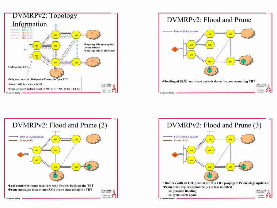
DVMRPv2: Topology Information
MR
MR
MR
MR MR
MR
MR
S1
S2
S3
S4
S5
TBT net S1TBT net S2TBT net S3TBT net S4TBT net S5
•Only one router is “Designated Forwarder” per TBT
•Router with best metric is DR
•If tie: lowest IP address wins! IP MC C < IP MC D, for TBT S3
Multi-access LANs
C
D
•Topology info recomputedevery minute
•Topology info in all routers
22
LANCASTERLANCASTERUNIVERSITYUNIVERSITY
ComputingDepartment© Laurent Mathy
DVMRPv2: Flood and Prune
MR
MR
MR
MR MR
MR
MR
R1
R2
S
Flow of (S,G) packets
•Flooding of (S,G) multicast packets down the corresponding TBT
23
LANCASTERLANCASTERUNIVERSITYUNIVERSITY
ComputingDepartment© Laurent Mathy
DVMRPv2: Flood and Prune (2)
MR
MR
MR
MR MR
MR
MR
R1
R2
S
Flow of (S,G) packetsPrune (S,G)
•Leaf routers without receivers send Prunes back up the TBT•Prune messages instantiate (S,G) prune state along the TBT
24
LANCASTERLANCASTERUNIVERSITYUNIVERSITY
ComputingDepartment© Laurent Mathy
DVMRPv2: Flood and Prune (3)
MR
MR
MR
MR MR
MR
MR
R1
R2
S
Flow of (S,G) packetsPrune (S,G)
• Routers with all OIF pruned for this TBT propagate Prune msgs upstream•Prune state expires periodically (~a few minutes)
⇒ periodic flooding⇒ cycle starts again
7
25
LANCASTERLANCASTERUNIVERSITYUNIVERSITY
ComputingDepartment© Laurent Mathy
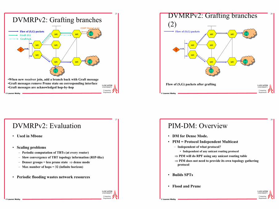
DVMRPv2: Grafting branches
MR
MR
MR
MR MR
MR
MR
R1
R2
S
Flow of (S,G) packets
R1
R2
S
Flow of (S,G) packetsGraft (G)
R3
IGMP Report (*,G)
GraftAck
•When new receiver join, add a branch back with Graft message•Graft messages remove Prune state on corresponding interface•Graft messages are acknowledged hop-by-hop
26
LANCASTERLANCASTERUNIVERSITYUNIVERSITY
ComputingDepartment© Laurent Mathy
DVMRPv2: Grafting branches (2)
MR
MR
MR
MR MR
MR
MR
R1
R2
S
Flow of (S,G) packets R3
Flow of (S,G) packets after grafting
27
LANCASTERLANCASTERUNIVERSITYUNIVERSITY
ComputingDepartment© Laurent Mathy
DVMRPv2: Evaluation• Used in Mbone
• Scaling problems– Periodic computation of TBTs (at every router)– Slow convergence of TBT topology information (RIP-like)– Denser groups = less prune state ⇒ dense mode – Max number of hops = 32 (infinite horizon)
• Periodic flooding wastes network resources
28
LANCASTERLANCASTERUNIVERSITYUNIVERSITY
ComputingDepartment© Laurent Mathy
PIM-DM: Overview• DM for Dense Mode.• PIM = Protocol Independent Multicast
– Independent of what protocol? • Independent of any unicast routing protocol
⇒ PIM will do RPF using any unicast routing table ⇒ PIM does not need to provide its own topology gathering
protocol
• Builds SPTs
• Flood and Prune
8
29
LANCASTERLANCASTERUNIVERSITYUNIVERSITY
ComputingDepartment© Laurent Mathy
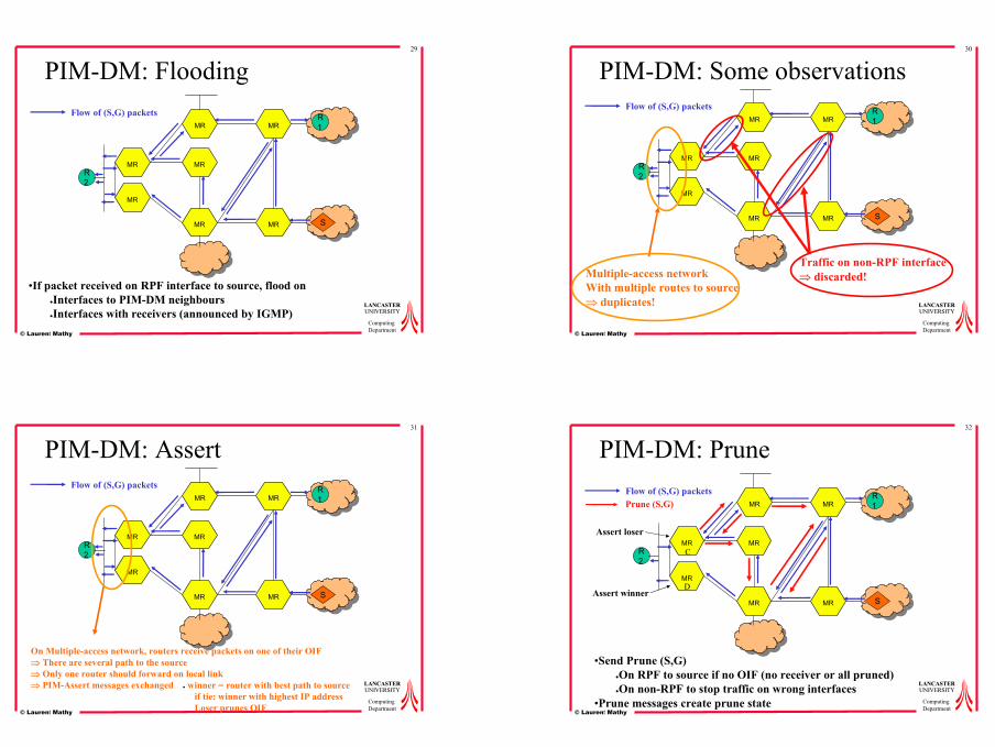
PIM-DM: Flooding
MR
MR
MR
MR MR
MR
MR
S
R1
R2
Flow of (S,G) packets
•If packet received on RPF interface to source, flood on●Interfaces to PIM-DM neighbours●Interfaces with receivers (announced by IGMP)
30
LANCASTERLANCASTERUNIVERSITYUNIVERSITY
ComputingDepartment© Laurent Mathy
PIM-DM: Some observations
MR
MR
MR
MR MR
MR
MR
S
R1
R2
Flow of (S,G) packets
Traffic on non-RPF interface⇒ discarded!Multiple-access network
With multiple routes to source⇒ duplicates!
31
LANCASTERLANCASTERUNIVERSITYUNIVERSITY
ComputingDepartment© Laurent Mathy
PIM-DM: Assert
MR
MR
MR
MR MR
MR
MR
S
R1
R2
Flow of (S,G) packets
On Multiple-access network, routers receive packets on one of their OIF⇒ There are several path to the source⇒ Only one router should forward on local link⇒ PIM-Assert messages exchanged ● winner = router with best path to source
if tie: winner with highest IP addressLoser prunes OIF
32
LANCASTERLANCASTERUNIVERSITYUNIVERSITY
ComputingDepartment© Laurent Mathy
PIM-DM: Prune
MR
MR
MR
MR MR
MR
MR
S
R1
R2
Flow of (S,G) packets
C
DAssert winner
Assert loser
Prune (S,G)
•Send Prune (S,G)●On RPF to source if no OIF (no receiver or all pruned)●On non-RPF to stop traffic on wrong interfaces
•Prune messages create prune state
9
33
LANCASTERLANCASTERUNIVERSITYUNIVERSITY
ComputingDepartment© Laurent Mathy
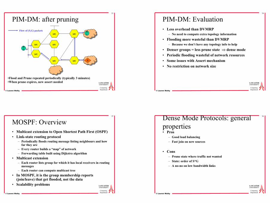
PIM-DM: after pruning
MR
MR
MR
MR MR
MR
MR
S
R1
R2
Flow of (S,G) packets
•Flood and Prune repeated periodically (typically 3 minutes)•When prune expires, new assert needed
34
LANCASTERLANCASTERUNIVERSITYUNIVERSITY
ComputingDepartment© Laurent Mathy
PIM-DM: Evaluation• Less overhead than DVMRP
– No need to compute extra topology information
• Flooding more wasteful than DVMRP– Because we don’t have any topology info to help
• Denser groups = less prune state ⇒ dense mode • Periodic flooding wasteful of network resources• Some issues with Assert mechanism• No restriction on network size
35
LANCASTERLANCASTERUNIVERSITYUNIVERSITY
ComputingDepartment© Laurent Mathy
MOSPF: Overview• Multicast extension to Open Shortest Path First (OSPF)• Link-state routing protocol
– Periodically floods routing message listing neighbours and how far they are
– Every router builds a “map” of network– Forwarding table built using Dijkstra algorithm
• Multicast extension– Each router lists group for which it has local receivers in routing
messages– Each router can compute multicast tree
• In MOSPF, it is the group membership reports (join/leave) that get flooded, not the data
• Scalability problems
36
LANCASTERLANCASTERUNIVERSITYUNIVERSITY
ComputingDepartment© Laurent Mathy
Dense Mode Protocols: general properties• Pros
– Good load balancing– Fast join on new sources
• Cons– Prune state where traffic not wanted– State: order of S*G– A no-no on low bandwidth links
10
37
LANCASTERLANCASTERUNIVERSITYUNIVERSITY
ComputingDepartment© Laurent Mathy
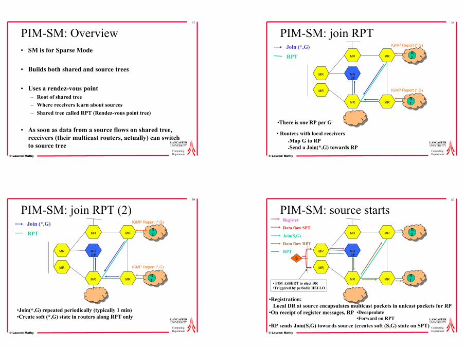
PIM-SM: Overview• SM is for Sparse Mode
• Builds both shared and source trees
• Uses a rendez-vous point– Root of shared tree– Where receivers learn about sources– Shared tree called RPT (Rendez-vous point tree)
• As soon as data from a source flows on shared tree, receivers (their multicast routers, actually) can switch to source tree
38
LANCASTERLANCASTERUNIVERSITYUNIVERSITY
ComputingDepartment© Laurent Mathy
PIM-SM: join RPT
MR
MR
MR
MR MR
MR
MR
R1
IGMP Report (*,G)
RP
IGMP Report (*,G)
R2
Join (*,G)
RPT
• Routers with local receivers ●Map G to RP●Send a Join(*,G) towards RP
•There is one RP per G
39
LANCASTERLANCASTERUNIVERSITYUNIVERSITY
ComputingDepartment© Laurent Mathy
PIM-SM: join RPT (2)
MR
MR
MR
MR MR
MR
MR
R1
IGMP Report (*,G)
RP
IGMP Report (*,G)
R2
Join (*,G)
RPT
•Join(*,G) repeated periodically (typically 1 min)•Create soft (*,G) state in routers along RPT only
40
LANCASTERLANCASTERUNIVERSITYUNIVERSITY
ComputingDepartment© Laurent Mathy
PIM-SM: source starts
MR
MR
MR
MR MR
MR
MR
R1
RP
R2
RPTS
Register
Data flow SPT
Join(S,G)
Data flow RPT
•Registration:Local DR at source encapsulates multicast packets in unicast packets for RP
•On receipt of register messages, RP
•RP sends Join(S,G) towards source (creates soft (S,G) state on SPT)
•Decapsulate•Forward on RPT
• PIM ASSERT to elect DR•Triggered by periodic HELLO
11
41
LANCASTERLANCASTERUNIVERSITYUNIVERSITY
ComputingDepartment© Laurent Mathy
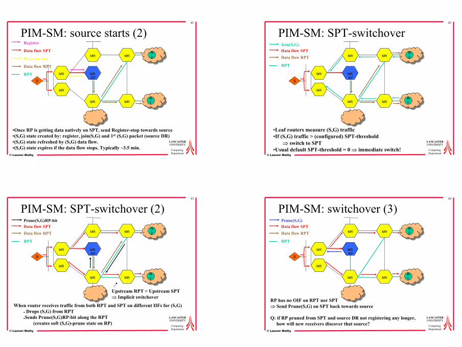
PIM-SM: source starts (2)
MR
MR
MR
MR MR
MR
MR
R1
RP
R2
RPTS
Register
Data flow SPT
Register-stop
Data flow RPT
•Once RP is getting data natively on SPT, send Register-stop towards source•(S,G) state created by: register, join(S,G) and 1st (S,G) packet (source DR)•(S,G) state refreshed by (S,G) data flow. •(S,G) state expires if the data flow stops. Typically ~3.5 min.
42
LANCASTERLANCASTERUNIVERSITYUNIVERSITY
ComputingDepartment© Laurent Mathy
PIM-SM: SPT-switchover
MR
MR
MR
MR MR
MR
MR
R1
RP
R2
RPT
S
Data flow SPTData flow RPT
Join(S,G)
•Leaf routers measure (S,G) traffic•If (S,G) traffic > (configured) SPT-threshold
⇒ switch to SPT•Usual default SPT-threshold = 0 ⇒ immediate switch!
43
LANCASTERLANCASTERUNIVERSITYUNIVERSITY
ComputingDepartment© Laurent Mathy
PIM-SM: SPT-switchover (2)
MR
MR
MR
MR MR
MR
MR
R1
RP
R2
RPT
S
Data flow SPTData flow RPT
Upstream RPT = Upstream SPT⇒ Implicit switchover
Prune(S,G)RP-bit
When router receives traffic from both RPT and SPT on different IIFs for (S,G)● Drops (S,G) from RPT●Sends Prune(S,G)RP-bit along the RPT
(creates soft (S,G)-prune state on RP)
44
LANCASTERLANCASTERUNIVERSITYUNIVERSITY
ComputingDepartment© Laurent Mathy
PIM-SM: switchover (3)
MR
MR
MR
MR MR
MR
MR
R1
RP
R2
RPT
S
Data flow SPTData flow RPT
Prune(S,G)
RP has no OIF on RPT nor SPT⇒ Send Prune(S,G) on SPT back towards source
Q: if RP pruned from SPT and source DR not registering any longer, how will new receivers discover that source?

12
45
LANCASTERLANCASTERUNIVERSITYUNIVERSITY
ComputingDepartment© Laurent Mathy
PIM-SM: switchover (4)
MR
MR
MR
MR MR
MR
MR
R1
RP
R2
RPT
S
Data flow SPTData flow RPT
R: Pruning (S,G) does not remove state, just installs prune state in the upstream router(i.e. gets the prune sender removed from the upstream OIFs)
⇒ RP still knows about (S,G) !⇒ This (S,G) state at RP will eventually time out due to lack of (S,G) data flow
46
LANCASTERLANCASTERUNIVERSITYUNIVERSITY
ComputingDepartment© Laurent Mathy
PIM-SM: switchover (5)• What happens when (S,G) state expires at RP?
– Actually, source DR periodically send a null-Register message– If it does not receive Register-stop from RP, resumes
registering– Null-Register resets (S,G) state in RP⇒No problem as long as register state timer at source DR is
smaller than (S,G) state timer at RP !!!⇒ When new receiver shows up, RP issues a join(S,G) on all its
(S,G) state for which it is not “joined”
47
LANCASTERLANCASTERUNIVERSITYUNIVERSITY
ComputingDepartment© Laurent Mathy
PIM-SM: RP discovery• Group-to-RP mapping must be the same for all PIM-
SM routers– Otherwise “black holes”
• 2 methods– Static configuration– Bootstrap Router (BSR)
• Each router configured to be a RP for group reports to BSR• BSR floods chosen set of group range-to-RPs to entire domain• Longest match of mcast address to group
– If several RPs possible, use hash function
• There is a third one, but Cisco proprietary…
48
LANCASTERLANCASTERUNIVERSITYUNIVERSITY
ComputingDepartment© Laurent Mathy
PIM-SM: evaluation• Based on periodic exchange of messages and soft state
⇒ Fail safe
• Uses both shared and shortest path trees– RPT: economical way to discover sources– SPT optimal path from a source
• PIM-SM is unidirectional• Traffic sent only where needed
⇒ OK also for larger groups
• Only real trouble is group address to RP mapping
13
49
LANCASTERLANCASTERUNIVERSITYUNIVERSITY
ComputingDepartment© Laurent Mathy
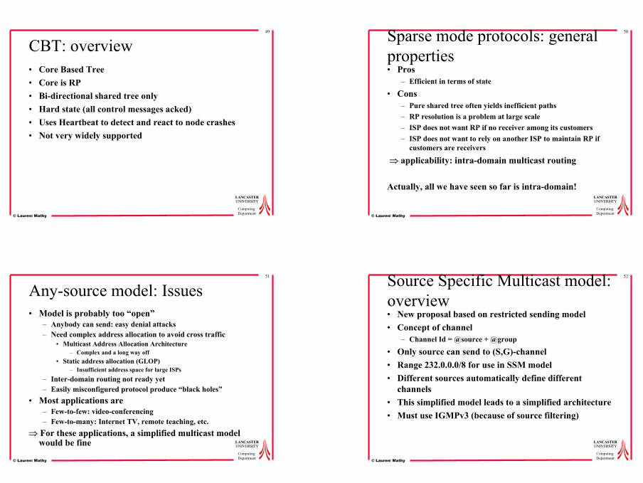
CBT: overview• Core Based Tree• Core is RP• Bi-directional shared tree only• Hard state (all control messages acked)• Uses Heartbeat to detect and react to node crashes• Not very widely supported
50
LANCASTERLANCASTERUNIVERSITYUNIVERSITY
ComputingDepartment© Laurent Mathy
Sparse mode protocols: general properties• Pros
– Efficient in terms of state
• Cons– Pure shared tree often yields inefficient paths– RP resolution is a problem at large scale– ISP does not want RP if no receiver among its customers– ISP does not want to rely on another ISP to maintain RP if
customers are receivers
⇒ applicability: intra-domain multicast routing
Actually, all we have seen so far is intra-domain!
51
LANCASTERLANCASTERUNIVERSITYUNIVERSITY
ComputingDepartment© Laurent Mathy
Any-source model: Issues• Model is probably too “open”
– Anybody can send: easy denial attacks– Need complex address allocation to avoid cross traffic
• Multicast Address Allocation Architecture– Complex and a long way off
• Static address allocation (GLOP)– Insufficient address space for large ISPs
– Inter-domain routing not ready yet– Easily misconfigured protocol produce “black holes”
• Most applications are – Few-to-few: video-conferencing– Few-to-many: Internet TV, remote teaching, etc.
⇒ For these applications, a simplified multicast model would be fine
52
LANCASTERLANCASTERUNIVERSITYUNIVERSITY
ComputingDepartment© Laurent Mathy
Source Specific Multicast model: overview• New proposal based on restricted sending model• Concept of channel
– Channel Id = @source + @group
• Only source can send to (S,G)-channel• Range 232.0.0.0/8 for use in SSM model• Different sources automatically define different
channels• This simplified model leads to a simplified architecture• Must use IGMPv3 (because of source filtering)

14
53
LANCASTERLANCASTERUNIVERSITYUNIVERSITY
ComputingDepartment© Laurent Mathy
Routing in SSM model• Several proposals
– Simple multicast, express
• PIM-SSM is in standardization track– We do not need a new protocol
• PIM-SM has already got Join(S,G)/Prune(S,G)• Modify PIM-SM so that DR issues Join(S,G) on receiving
IGMPv3 source specific reports on range 232.0.0.0/8• This just by-passes RP• Range 232.0.0.0/8 must not be allow in PIM-SM
• The only thing is to discover channel– Usually out-of-band: web, email, directory, etc.
54
LANCASTERLANCASTERUNIVERSITYUNIVERSITY
ComputingDepartment© Laurent Mathy
PIM-SSM: evaluation• Receivers directly join SPT for (S,G) tree
– Any other source will fail RPF-check even if spoofing (except source on same multi-access net)
– RP mapping problem removed⇒ this is even easy for inter-domain
– Multicast address allocation reduced to a trivial local problem• Everybody is given the full 232.0.0.0/8 range !
– “State” and “Path” efficient
55
LANCASTERLANCASTERUNIVERSITYUNIVERSITY
ComputingDepartment© Laurent Mathy
PIM-SSM: Issues• Issues
– No more multicast back-channel from receivers• RTP/RTCP is broken
– Must at least deploy proxies to correct problem• Resource discovery (based on ERS) won’t work
• IGMPv3 is not here yet– Q: How do I deploy PIM-SSM without it?– R: Cisco’s dirty hack is URD
56
LANCASTERLANCASTERUNIVERSITYUNIVERSITY
ComputingDepartment© Laurent Mathy
Multicast tree characteristics• Study by Chalmers and Almeroth (Infocom 2001)
shows that – Between 60% and 80% of non-leaf tree nodes exhibit an out-
degree of 1, i.e. they are just “relays” (one in, one out)– Most of the branching is done either near the root or the leaves– Probably due to
• Constraints by underlying network connectivity• Clustering of receivers
• Question: since most multicast routers are found not to be branching points, should you bother deploying them everywhere, or mostly where branching points are likely (i.e. edge of the network)?

15
57
LANCASTERLANCASTERUNIVERSITYUNIVERSITY
ComputingDepartment© Laurent Mathy
Deployment of multicast• Partial deployment
– Multicast routing protocols assume all routers are multicast⇒ If partial deployment, multicast routers must be logically
connected to each other by tunnels– Tunnels can either be IP-in-IP or MPLS tunnels
• Better control on multicast traffic• MPLS can provide traffic engineering for multicast traffic
– e.g. direct multicast traffic away from busy core links
– There are fewer routers• Fewer opportunities to misconfigure your network• Need one multicast router with “physical” link to each multicast
client/source
58
LANCASTERLANCASTERUNIVERSITYUNIVERSITY
ComputingDepartment© Laurent Mathy
Deployment of multicast (2)• Partial deployment has got downfall too
– Fewer routers means less load balancing– The multicast routing protocol must run it own unicast routing
protocol• Otherwise RPF check could fail (= black holes)!• Duplicate functionality: more overhead (memory + control msgs)
– Multicast routing is still very efficient on tunnel overlayBUT you can now get multiple copies of the same data on a physical link if that link traversed by several tunnels
– Tunnels are another opportunity to misconfigure…
• The alternative is a protocol that is specifically designed to set-up dynamic tunnels in a partial deployment environment...
59
LANCASTERLANCASTERUNIVERSITYUNIVERSITY
ComputingDepartment© Laurent Mathy
HBH - Reunite• Hop-By-Hop multicast (HBH)/reunite are specifically
designed for partial deployment• All signalling uses unicast to source, intercepted in HBH
(reunite) routers• Tree implemented as dynamic unicast tunnels between
HBH/reunite routers– The more routers speak the protocol, the better the tree– Sort of “recursive” unicast between multicast routers
• Particularly suited to Source-specific model
60
LANCASTERLANCASTERUNIVERSITYUNIVERSITY
ComputingDepartment© Laurent Mathy
IP MulticastSo far, all solutions have required
introduction of special functionality in routers...
Is there another way?
Actually, yes…
16
61
LANCASTERLANCASTERUNIVERSITYUNIVERSITY
ComputingDepartmentLaurent Mathy
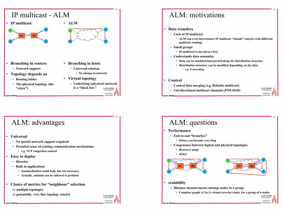
IP multicast - ALM• IP multicast
• Branching in routers– Network support
• Topology depends on– Routing tables– The physical topology (the
“wires”)
• ALM
• Branching in hosts– Universal solution
• No change in network
• Virtual topology– Underlying (physical) network
is a “black box”
1
4
2
3
R1 R2
1
4
2
3
62
LANCASTERLANCASTERUNIVERSITYUNIVERSITY
ComputingDepartmentLaurent Mathy
ALM: motivations
• Data transfers– Lack of IP multicast
• ALM can even interconnect IP multicast “islands” (maybe with different multicast routing)
– Small groups• IP multicast is not always best
– Understands data semantics• Data can be modified/interpreted along the distribution structure• Distribution structure can be modified depending on the data
– e.g. Transcoding
• Control– Control data merging (e.g. Reliable multicast)– Uni-directional multicast channels (PIM-SSM)
63
LANCASTERLANCASTERUNIVERSITYUNIVERSITY
ComputingDepartmentLaurent Mathy
ALM: advantages
• Universal– No special network support required– Potential reuse of existing communication mechanisms
• e.g. TCP congestion control
• Easy to deploy– libraries – Built in applications
• standardisation could help, but not necessary• Actually, solution can be tailored to problem
• Choice of metrics for “neighbour” selection⇒ multiple topologies⇒ potentially, very fine topology control
64
LANCASTERLANCASTERUNIVERSITYUNIVERSITY
ComputingDepartmentLaurent Mathy
ALM: questions• Performance
– End-to-end “branches”• Delays can become very long
– Congruence between logical and physical topologies• Resource usage• delays
• scalability– Distance measurements amongs nodes in a group
• Complete graph: n*(n-1) virtual (overlay) links, for a group of n nodes
1
4
2
3
R1 R2
1
4
2
3
R1 R2

17
65
LANCASTERLANCASTERUNIVERSITYUNIVERSITY
ComputingDepartmentLaurent Mathy
Multicast applicatif: questions (2)• stability
– of the nodes• Overlay nodes are hosts
– Less reliable than routers– Come and go
• Nevertherless, loss of a neighbour is often caused by reasons local to that neighbour, rather than a connectivity problem
⇒ the overlay is often easy to repair: only need to find a new neighbour» Furthermore, it is easy to add redundancy
– of the measurements• “accuracy” of the overlay depends upon the variation rate of the metric
chosen– Think of RTT or BW in the Internet
• Must weigh accuracy and overheads
66
LANCASTERLANCASTERUNIVERSITYUNIVERSITY
ComputingDepartmentLaurent Mathy
General Strategy• Most ALM solutions take previous issues into account, but one
thing is sure: it will never be as efficient as IP multicast– Different tradeoffs are the basis of different solutions
• It is “multicast”, so ultimately the goal is to build a tree• A tree can be constrained (there is a limit on the number of
children for each node) or not• The “quality” of a tree depends on what it is used for!
– Some algorithms allow the use of different criteria
• We will only look at “dynamic” solutions– Not multiple unicast («reflector»), nor static (predifined) topologies
67
LANCASTERLANCASTERUNIVERSITYUNIVERSITY
ComputingDepartmentLaurent Mathy
Taxonomy
Centralisedalgo
Distributedalgo
graph/tree Tree first
tree/graph Limited horizon
Clusters
infrastructure spontaneouscoordinates
Partialknowledge
Completeknowledge
HBMALMI
BayeuxScribe
Delaunaytriangulation
NaradaScattercast
YOID OvercastTBCP
NICE
CAN mcast
SHDC
68
LANCASTERLANCASTERUNIVERSITYUNIVERSITY
ComputingDepartmentLaurent Mathy
Host Based Multicast (HBM)• Centralised algorithm• Rendez-vous point (RP) collects a complete measurement
graph from the participants• Periodic measurements sent to RP
– RP assigns a “capability” to each node: Disconnected, leaf, transit
• Topologies: tree, ring, hybrid– “redundant links” for robustness
• These links are clearly marked• Periodic data
– If link is redundant (data already received on regular link), receiver imposes a “silent period” (message SUSPEND)
– otherwise, (small) wait and report to RP is situation persists• Fault detection
– heartbeats or exploitation of the properties of the topology
• Faults or membership changes reported to RP and topology is recalculated
18
69
LANCASTERLANCASTERUNIVERSITYUNIVERSITY
ComputingDepartmentLaurent Mathy
HBM (2)
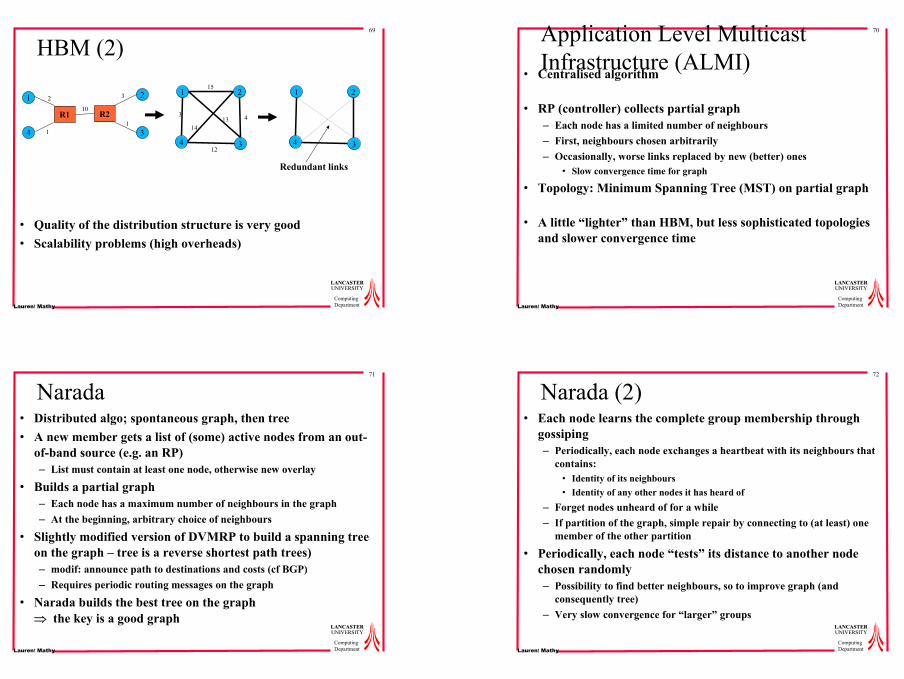
• Quality of the distribution structure is very good• Scalability problems (high overheads)
4
1 2
3
1
4
2
3
R1 R2
2
10
3
11
15
133 4
14
124
1 2
3
Redundant links
70
LANCASTERLANCASTERUNIVERSITYUNIVERSITY
ComputingDepartmentLaurent Mathy
Application Level Multicast Infrastructure (ALMI)
• Centralised algorithm
• RP (controller) collects partial graph– Each node has a limited number of neighbours– First, neighbours chosen arbitrarily– Occasionally, worse links replaced by new (better) ones
• Slow convergence time for graph
• Topology: Minimum Spanning Tree (MST) on partial graph
• A little “lighter” than HBM, but less sophisticated topologies and slower convergence time
71
LANCASTERLANCASTERUNIVERSITYUNIVERSITY
ComputingDepartmentLaurent Mathy
Narada• Distributed algo; spontaneous graph, then tree• A new member gets a list of (some) active nodes from an out-
of-band source (e.g. an RP)– List must contain at least one node, otherwise new overlay
• Builds a partial graph– Each node has a maximum number of neighbours in the graph– At the beginning, arbitrary choice of neighbours
• Slightly modified version of DVMRP to build a spanning tree on the graph – tree is a reverse shortest path trees)– modif: announce path to destinations and costs (cf BGP)– Requires periodic routing messages on the graph
• Narada builds the best tree on the graph⇒ the key is a good graph
72
LANCASTERLANCASTERUNIVERSITYUNIVERSITY
ComputingDepartmentLaurent Mathy
Narada (2)• Each node learns the complete group membership through
gossiping– Periodically, each node exchanges a heartbeat with its neighbours that
contains:• Identity of its neighbours• Identity of any other nodes it has heard of
– Forget nodes unheard of for a while– If partition of the graph, simple repair by connecting to (at least) one
member of the other partition
• Periodically, each node “tests” its distance to another node chosen randomly – Possibility to find better neighbours, so to improve graph (and
consequently tree)– Very slow convergence for “larger” groups
19
73
LANCASTERLANCASTERUNIVERSITYUNIVERSITY
ComputingDepartmentLaurent Mathy
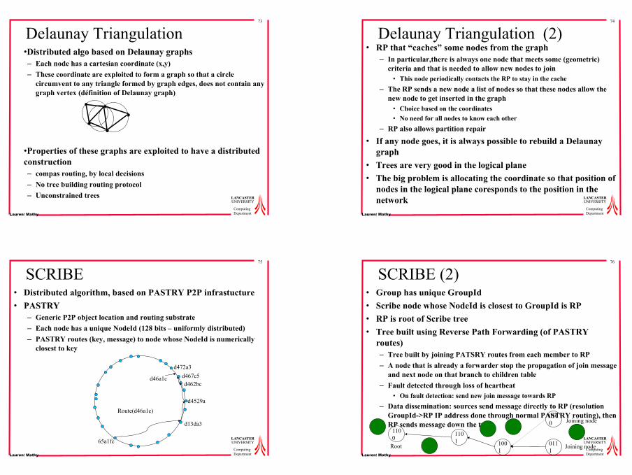
Delaunay Triangulation •Distributed algo based on Delaunay graphs– Each node has a cartesian coordinate (x,y)– These coordinate are exploited to form a graph so that a circle
circumvent to any triangle formed by graph edges, does not contain any graph vertex (définition of Delaunay graph)
•Properties of these graphs are exploited to have a distributed construction– compas routing, by local decisions– No tree building routing protocol– Unconstrained trees
74
LANCASTERLANCASTERUNIVERSITYUNIVERSITY
ComputingDepartmentLaurent Mathy
Delaunay Triangulation (2)• RP that “caches” some nodes from the graph
– In particular,there is always one node that meets some (geometric) criteria and that is needed to allow new nodes to join
• This node periodically contacts the RP to stay in the cache– The RP sends a new node a list of nodes so that these nodes allow the
new node to get inserted in the graph• Choice based on the coordinates• No need for all nodes to know each other
– RP also allows partition repair
• If any node goes, it is always possible to rebuild a Delaunay graph
• Trees are very good in the logical plane• The big problem is allocating the coordinate so that position of
nodes in the logical plane coresponds to the position in the network
75
LANCASTERLANCASTERUNIVERSITYUNIVERSITY
ComputingDepartmentLaurent Mathy
SCRIBE• Distributed algorithm, based on PASTRY P2P infrastucture• PASTRY
– Generic P2P object location and routing substrate– Each node has a unique NodeId (128 bits – uniformly distributed)– PASTRY routes (key, message) to node whose NodeId is numerically
closest to key
65a1fc
d46a1c
Route(d46a1c)
d13da3
d4529a
d462bcd467c5
d472a3
76
LANCASTERLANCASTERUNIVERSITYUNIVERSITY
ComputingDepartmentLaurent Mathy
SCRIBE (2)• Group has unique GroupId• Scribe node whose NodeId is closest to GroupId is RP• RP is root of Scribe tree• Tree built using Reverse Path Forwarding (of PASTRY
routes)– Tree built by joining PATSRY routes from each member to RP– A node that is already a forwarder stop the propagation of join message
and next node on that branch to children table– Fault detected through loss of heartbeat
• On fault detection: send new join message towards RP– Data dissemination: sources send message directly to RP (resolution
GroupId->RP IP address done through normal PASTRY routing), then RP sends message down the tree
0111
0100
1001
1101
1100
Root
Joining node
Joining node

20
77
LANCASTERLANCASTERUNIVERSITYUNIVERSITY
ComputingDepartmentLaurent Mathy
SCRIBE (3)• SCRIBE leverages PASTRY properties for self-organisation,
robustness, resilience, routing, scalability, etc.• Unconstrained trees• Nodes in a SCRIBE tree are not necessarily group members
– Real p2p approach: a node may have to forward even though not interested to consume/receive data
• Often, group members are actually tree leaves• Root can be group member if Group Id chosen cleverly
– Very good scalability and performance over a large ( > 100K nodes) PASTRY substrate
• But will not be as good if p2p infrastructure is not large– What happens if as many Scribe nodes as group member in the PASTRY
overlay? Likely multiple unicast unless group is very large...
– Congruence of ALM tree to physical topology depends on PASTRY congruence
• This is a point where PASTRY is “shady”– Proposes to use Expanding Ring Searches, which would violate ALM
universality
78
LANCASTERLANCASTERUNIVERSITYUNIVERSITY
ComputingDepartmentLaurent Mathy
Multi-CAN• Multicast over Content Addressable Network (CAN)• CAN
– A CAN is a virtual d-dimensional Cartesian coordinate space on a d-torus
– Nodes have coordinates in the space and the space is partitioned in as many “zones” as there are nodes – each node “own” a zone
– Content is “hashed” onto a coordinate• Coresponding zone owner holds either content or reference to it
– Can is capable of routing message to a coordinate (actually owner of zone that contains the coordinate), in a hop-by-hop manner (i.e. From neighbouring zone to neighbouring zone)
CAN with 15 nodes
Routing path
79
LANCASTERLANCASTERUNIVERSITYUNIVERSITY
ComputingDepartmentLaurent Mathy
Multi-CAN (2)• Multicast over CAN: flooding
– Source send to all its neighbours– Node receive message along
dimension i• Forward to all neighbours along
dimensions 1..(i-1)• Forward to neighbours alond
dim i only on “opposite side”from receive side
• If message gone ½ way across space: do not forward – loop avoidance
• Remember sequence number, do not duplicate
80
LANCASTERLANCASTERUNIVERSITYUNIVERSITY
ComputingDepartmentLaurent Mathy
Multi-CAN (3)• One overlay per group
– Existence of larger CAN can be used as bootstrap
• No tree!• Duplicates• Relies on CAN for efficiency, resilience, performance, etc
– Performance good on virtual structure, but– Congruence between CAN and physical network is not prime concern
• But methods proposed to improve congruence– Binning
21
81
LANCASTERLANCASTERUNIVERSITYUNIVERSITY
ComputingDepartmentLaurent Mathy
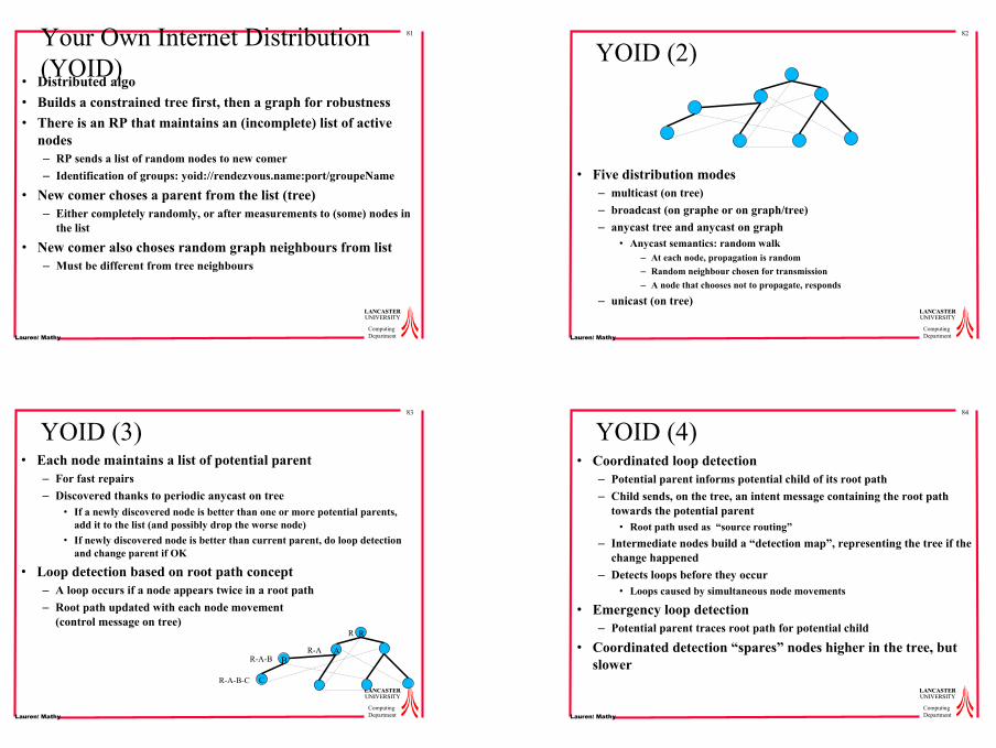
Your Own Internet Distribution (YOID)
• Distributed algo• Builds a constrained tree first, then a graph for robustness• There is an RP that maintains an (incomplete) list of active
nodes– RP sends a list of random nodes to new comer– Identification of groups: yoid://rendezvous.name:port/groupeName
• New comer choses a parent from the list (tree)– Either completely randomly, or after measurements to (some) nodes in
the list
• New comer also choses random graph neighbours from list– Must be different from tree neighbours
82
LANCASTERLANCASTERUNIVERSITYUNIVERSITY
ComputingDepartmentLaurent Mathy
YOID (2)
• Five distribution modes– multicast (on tree)– broadcast (on graphe or on graph/tree)– anycast tree and anycast on graph
• Anycast semantics: random walk– At each node, propagation is random– Random neighbour chosen for transmission– A node that chooses not to propagate, responds
– unicast (on tree)
83
LANCASTERLANCASTERUNIVERSITYUNIVERSITY
ComputingDepartmentLaurent Mathy
YOID (3)• Each node maintains a list of potential parent
– For fast repairs– Discovered thanks to periodic anycast on tree
• If a newly discovered node is better than one or more potential parents, add it to the list (and possibly drop the worse node)
• If newly discovered node is better than current parent, do loop detection and change parent if OK
• Loop detection based on root path concept– A loop occurs if a node appears twice in a root path– Root path updated with each node movement
(control message on tree)R
AB
R
R-AR-A-B
CR-A-B-C
84
LANCASTERLANCASTERUNIVERSITYUNIVERSITY
ComputingDepartmentLaurent Mathy
YOID (4)• Coordinated loop detection
– Potential parent informs potential child of its root path– Child sends, on the tree, an intent message containing the root path
towards the potential parent• Root path used as “source routing”
– Intermediate nodes build a “detection map”, representing the tree if the change happened
– Detects loops before they occur• Loops caused by simultaneous node movements
• Emergency loop detection – Potential parent traces root path for potential child
• Coordinated detection “spares” nodes higher in the tree, but slower
22
85
LANCASTERLANCASTERUNIVERSITYUNIVERSITY
ComputingDepartmentLaurent Mathy
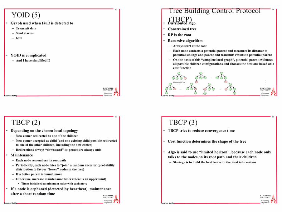
YOID (5)• Graph used when fault is detected to
– Transmit data– Send alarms– both
• YOID is complicated– And I have simplified!!!
86
LANCASTERLANCASTERUNIVERSITYUNIVERSITY
ComputingDepartmentLaurent Mathy
Tree Building Control Protocol (TBCP)
• Distributed algo• Constrained tree• RP is the root• Recursive algorithm
– Always start at the root– Each node contacts a potential parent and measures its distance to
potential siblings and parent and transmits results to potential parent– On the basis of this “complete local graph”, potential parent evaluates
all possible children configurations and chooses the best one based on a cost function
P
NC2C1 C3
If fanout of P ≥ 4
P
N
C2C1 C3
P
N
C2C1 C3…
P
N C2
C1
C3
P
NC2
C3
C1 …
P
N C2
C1
C3
P
NC2
C3
C1 …
.
.
.
87
LANCASTERLANCASTERUNIVERSITYUNIVERSITY
ComputingDepartmentLaurent Mathy
TBCP (2)• Depending on the chosen local topology
– New comer redirected to one of the children– New comer accepted as child (and one existing child possible redirected
to one of the other children, including the new comer)– Redirections always “downward” ⇒ procedure always ends
• Maintenance– Each node remembers its root path– Periodically, each node tries to “join” a random ancestor (probability
distribution to favour “lower” nodes in the tree)– If a better parent is found, move– Otherwise, increase maintenance timer (there is an upper limit)
• Timer initialised at minimum value with each move
• If a node is orphaned (detected by heartbeat), maintenance after a short random time
88
LANCASTERLANCASTERUNIVERSITYUNIVERSITY
ComputingDepartmentLaurent Mathy
TBCP (3)• TBCP tries to reduce convergence time
• Cost function determines the shape of the tree
• Algo is said to use “limited horizon”, because each node only talks to the nodes on its root path and their children– Startegy is to build the best tree with the least information
23
89
LANCASTERLANCASTERUNIVERSITYUNIVERSITY
ComputingDepartmentLaurent Mathy
Overcast
• Same approach asTBCP, but– Unconstrained tree– Metric is BW only
• 10 Kbytes measurement samples• If BW difference between 2 nodes is less then 10%, the closest is chosen
(detremined by traceroute !)– A node tries to get as far as possible from the root
• It is for non interactive distribution
90
LANCASTERLANCASTERUNIVERSITYUNIVERSITY
ComputingDepartmentLaurent Mathy
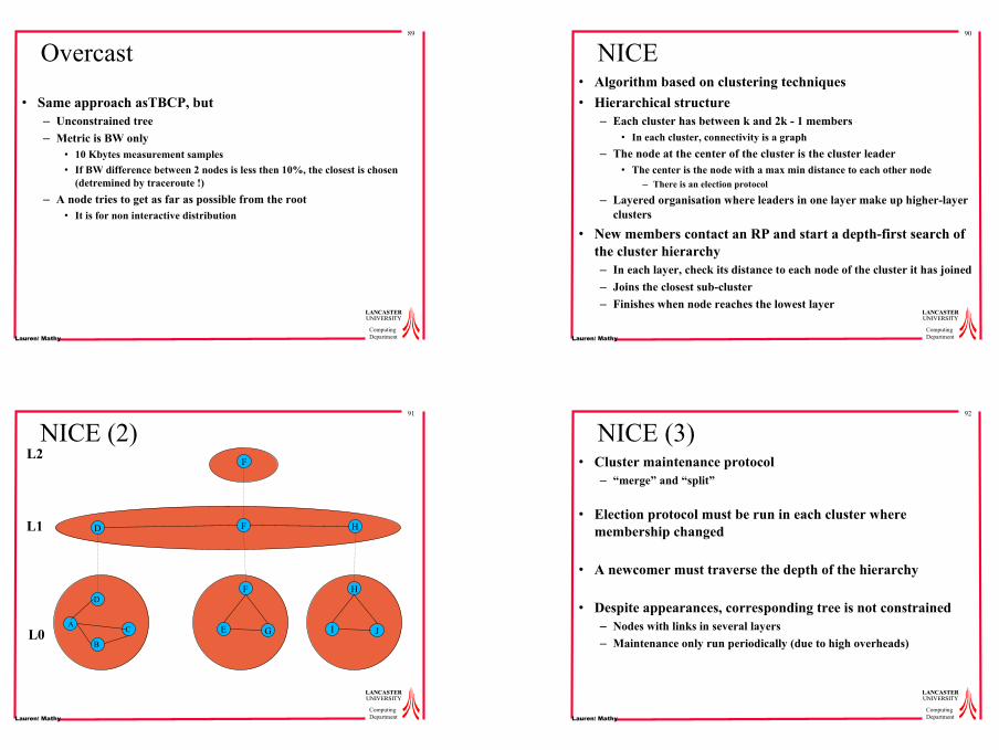
NICE• Algorithm based on clustering techniques• Hierarchical structure
– Each cluster has between k and 2k - 1 members• In each cluster, connectivity is a graph
– The node at the center of the cluster is the cluster leader• The center is the node with a max min distance to each other node
– There is an election protocol
– Layered organisation where leaders in one layer make up higher-layer clusters
• New members contact an RP and start a depth-first search of the cluster hierarchy– In each layer, check its distance to each node of the cluster it has joined– Joins the closest sub-cluster– Finishes when node reaches the lowest layer
91
LANCASTERLANCASTERUNIVERSITYUNIVERSITY
ComputingDepartmentLaurent Mathy
NICE (2)
D F
E
F
H
F
GA
B
C
D
I
H
JL0
L1
L2
92
LANCASTERLANCASTERUNIVERSITYUNIVERSITY
ComputingDepartmentLaurent Mathy
NICE (3)• Cluster maintenance protocol
– “merge” and “split”
• Election protocol must be run in each cluster where membership changed
• A newcomer must traverse the depth of the hierarchy
• Despite appearances, corresponding tree is not constrained– Nodes with links in several layers– Maintenance only run periodically (due to high overheads)
24
93
LANCASTERLANCASTERUNIVERSITYUNIVERSITY
ComputingDepartmentLaurent Mathy
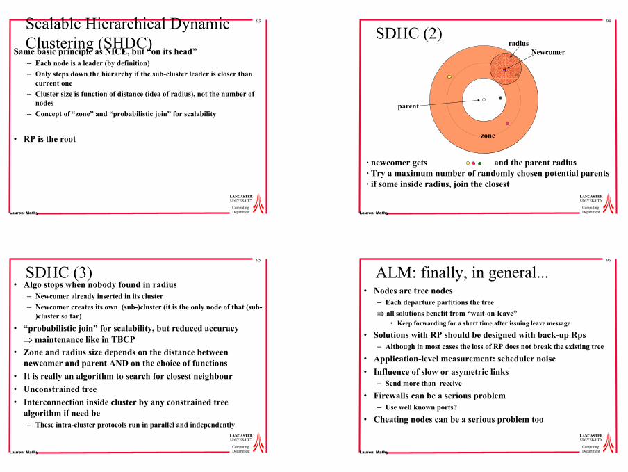
Scalable Hierarchical Dynamic Clustering (SHDC)
Same basic principle as NICE, but “on its head”– Each node is a leader (by definition)– Only steps down the hierarchy if the sub-cluster leader is closer than
current one– Cluster size is function of distance (idea of radius), not the number of
nodes– Concept of “zone” and “probabilistic join” for scalability
• RP is the root
94
LANCASTERLANCASTERUNIVERSITYUNIVERSITY
ComputingDepartmentLaurent Mathy
SDHC (2)Newcomer
zone
parent
radius
· newcomer gets and the parent radius· Try a maximum number of randomly chosen potential parents· if some inside radius, join the closest
95
LANCASTERLANCASTERUNIVERSITYUNIVERSITY
ComputingDepartmentLaurent Mathy
SDHC (3)• Algo stops when nobody found in radius
– Newcomer already inserted in its cluster– Newcomer creates its own (sub-)cluster (it is the only node of that (sub-
)cluster so far)
• “probabilistic join” for scalability, but reduced accuracy⇒ maintenance like in TBCP
• Zone and radius size depends on the distance between newcomer and parent AND on the choice of functions
• It is really an algorithm to search for closest neighbour• Unconstrained tree• Interconnection inside cluster by any constrained tree
algorithm if need be– These intra-cluster protocols run in parallel and independently
96
LANCASTERLANCASTERUNIVERSITYUNIVERSITY
ComputingDepartmentLaurent Mathy
ALM: finally, in general...• Nodes are tree nodes
– Each departure partitions the tree⇒ all solutions benefit from “wait-on-leave”
• Keep forwarding for a short time after issuing leave message
• Solutions with RP should be designed with back-up Rps– Although in most cases the loss of RP does not break the existing tree
• Application-level measurement: scheduler noise• Influence of slow or asymetric links
– Send more than receive
• Firewalls can be a serious problem– Use well known ports?
• Cheating nodes can be a serious problem too
25
97
LANCASTERLANCASTERUNIVERSITYUNIVERSITY
ComputingDepartmentLaurent Mathy
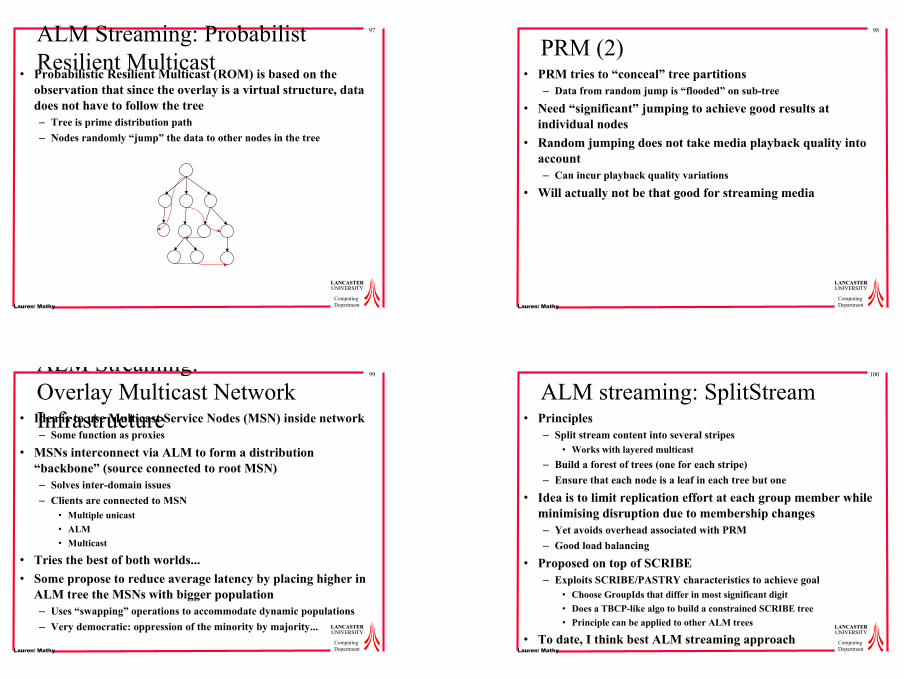
ALM Streaming: Probabilist Resilient Multicast
• Probabilistic Resilient Multicast (ROM) is based on the observation that since the overlay is a virtual structure, data does not have to follow the tree– Tree is prime distribution path– Nodes randomly “jump” the data to other nodes in the tree
98
LANCASTERLANCASTERUNIVERSITYUNIVERSITY
ComputingDepartmentLaurent Mathy
PRM (2)• PRM tries to “conceal” tree partitions
– Data from random jump is “flooded” on sub-tree
• Need “significant” jumping to achieve good results at individual nodes
• Random jumping does not take media playback quality into account – Can incur playback quality variations
• Will actually not be that good for streaming media
99
LANCASTERLANCASTERUNIVERSITYUNIVERSITY
ComputingDepartmentLaurent Mathy
ALM Streaming:Overlay Multicast Network Infrastructure• Idea is to use Multicast Service Nodes (MSN) inside network– Some function as proxies
• MSNs interconnect via ALM to form a distribution “backbone” (source connected to root MSN)– Solves inter-domain issues– Clients are connected to MSN
• Multiple unicast• ALM• Multicast
• Tries the best of both worlds...• Some propose to reduce average latency by placing higher in
ALM tree the MSNs with bigger population– Uses “swapping” operations to accommodate dynamic populations– Very democratic: oppression of the minority by majority...
100
LANCASTERLANCASTERUNIVERSITYUNIVERSITY
ComputingDepartmentLaurent Mathy
ALM streaming: SplitStream• Principles
– Split stream content into several stripes• Works with layered multicast
– Build a forest of trees (one for each stripe)– Ensure that each node is a leaf in each tree but one
• Idea is to limit replication effort at each group member while minimising disruption due to membership changes– Yet avoids overhead associated with PRM– Good load balancing
• Proposed on top of SCRIBE– Exploits SCRIBE/PASTRY characteristics to achieve goal
• Choose GroupIds that differ in most significant digit• Does a TBCP-like algo to build a constrained SCRIBE tree• Principle can be applied to other ALM trees
• To date, I think best ALM streaming approach
26
101
LANCASTERLANCASTERUNIVERSITYUNIVERSITY
ComputingDepartmentLaurent Mathy
Exploiting Application Semantics
• Resource constraints mean a limit (a.k.a out-degree) on number of replication per node– Influences tree structure
• Data propagation depends on the tree structure, not on the application communication structure
⇒ audio-conferencing: take conversation structure (i.e. Turn taking) into account, while respecting resource constraints
102
LANCASTERLANCASTERUNIVERSITYUNIVERSITY
ComputingDepartmentLaurent Mathy
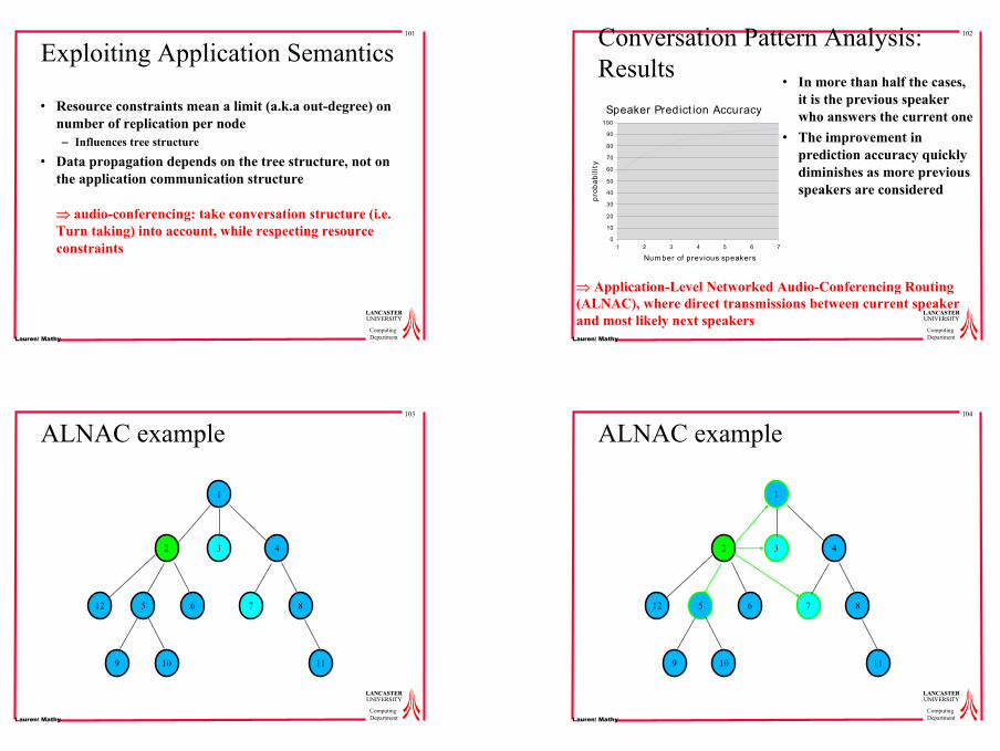
Conversation Pattern Analysis: Results
• In more than half the cases, it is the previous speaker who answers the current one
• The improvement in prediction accuracy quickly diminishes as more previous speakers are considered
1 2 3 4 5 6 70
10
20
30
40
50
60
70
80
90
100
Speaker Predict ion Accuracy
Num ber of previous speakers
prob
abili
ty
⇒ Application-Level Networked Audio-Conferencing Routing (ALNAC), where direct transmissions between current speaker and most likely next speakers
103
LANCASTERLANCASTERUNIVERSITYUNIVERSITY
ComputingDepartmentLaurent Mathy
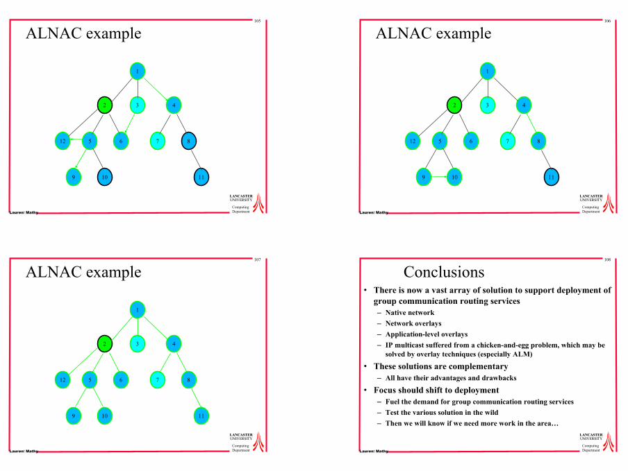
ALNAC example
1
3 42
5 6 7 8
9 10 11
12
104
LANCASTERLANCASTERUNIVERSITYUNIVERSITY
ComputingDepartmentLaurent Mathy
ALNAC example
1
3 42
5 6 7 8
9 10 11
12
27
105
LANCASTERLANCASTERUNIVERSITYUNIVERSITY
ComputingDepartmentLaurent Mathy
ALNAC example
1
3 42
5 6 7 8
9 10 11
12
106
LANCASTERLANCASTERUNIVERSITYUNIVERSITY
ComputingDepartmentLaurent Mathy
ALNAC example
1
3 42
5 6 7 8
9 10 11
12
107
LANCASTERLANCASTERUNIVERSITYUNIVERSITY
ComputingDepartmentLaurent Mathy
ALNAC example
1
3 42
5 6 7 8
9 10 11
12
108
LANCASTERLANCASTERUNIVERSITYUNIVERSITY
ComputingDepartmentLaurent Mathy
Conclusions• There is now a vast array of solution to support deployment of
group communication routing services– Native network– Network overlays– Application-level overlays– IP multicast suffered from a chicken-and-egg problem, which may be
solved by overlay techniques (especially ALM)
• These solutions are complementary– All have their advantages and drawbacks
• Focus should shift to deployment– Fuel the demand for group communication routing services– Test the various solution in the wild– Then we will know if we need more work in the area…