1. 2. 3. minimum distance from wall / ceiling · (7) insert the universal drywall bracket into hole...
TRANSCRIPT

© 2018. Apure Distribution LLC. All specifications and dimensions subject to change without notice. visit www.apure-system.com to download the latest versions of all specifi-cations. Apure Distribution LLC, 5555 Biscayne Blvd, Fourth Floor, Miami, Florida 33137 | phone: +1 305 351 1025 | Patent Pending
important SAFETY instructionsREAD carefully, SAVE these instructions, DELIVER to owner after installation
APURE MINUS THREE: INSTALLATION SEQUENCE USING THE UNIVERSAL DRYWALL BRACKET
12/18 page 1 of 5
(1) Confirm fixture placement in the illumination plan, if applicable. If fixture placement from the wall or ceiling is not defined, the minimum recommended distance for even light distribution is 35.5” (90cm) from the wall/ceiling to the center of the universal drywall bracket. (2) The universal drywall bracket (AM3-BRK-U) measures 300mm X 209mm. Ensure that the existing framing or studs will not interfere with the intended fixture location including mounting bracket!(3) Ensure that the fixture will not impact studs or framing behind drywall!(4) Use the included bracket as a template to mark square cut lines and 4x drill locations onto the existing drywall. (5) Cut a square opening 8.25” X 8.25”(209mm X 209mm) that was marked during step (4).(6) Drill 4x holes marked using template in step (4).
• DO NOT INSTALL DAMAGED PRODUCT! Upon receipt, thoroughly inspect for any freight damage which should be brought to the attention of the delivery carrier.
• Compare the catalog description listed on the packing slip with the label on the carton to ensure you have received the correct merchandise.
• Read and familiarize yourself with the nomenclature and instructions before starting installation.• RISK OF ELECTRIC SHOCK! Turn off electricity at the breaker panel or fuse box and follow NEC and all local
electrical building codes and practices. • RISK OF INJURY! Avoid direct eye exposure to the light source while it is on.• Do not install directly to line voltage! Remote power supply is required. Follow all instructions by the manufacturer!• Do not power on fixture with installation plug inserted.• Avoid direct contact with light source. The fixture lens must have a minumum clearance of 1 foot (30cm) at all times.• Do not submerge this product under water.
MINIMUM DISTANCE FROM WALL / CEILING
from bracket center
minimum 35.5” (90cm)
1. 2. 3.
4. 5. 6.

(7) Insert the universal drywall bracket into hole created during step (5). The flanges along the side of the bracket must always face upwards!(8) Insert 4 included screws through the drywall holes created during step (6) and reach into opening in order to install 4 wing-nuts to secure the installation bracket.(9) Remove the red lens protector carefully by unscrewing the two screws. Do not discard of the cover and screws!(10) The fixture lens is extremely delicate, do not touch the lens!(11) Carefully install the Minus fixture (AM31F) onto installation board using included pointed drywall screws.(12) Make the low-voltage electrical connection. The white wire indicates the positive pole, the black the negative pole. Electrical connectors and 16AWG wire NOT included.
TEST ALL CONNECTIONS AND ENSURE FIXTURE IS WORKING PROPERLY BEFORE PROCEEDING.
White (+)Black (-)
Flanges must face upwards!
important SAFETY instructionsREAD carefully, SAVE these instructions, DELIVER to owner after installation
APURE MINUS THREE: INSTALLATION SEQUENCE USING THE UNIVERSAL DRYWALL BRACKET• DO NOT INSTALL DAMAGED PRODUCT! Upon receipt, thoroughly inspect for any freight damage which should be
brought to the attention of the delivery carrier. • Compare the catalog description listed on the packing slip with the label on the carton to ensure you have received
the correct merchandise.• Read and familiarize yourself with the nomenclature and instructions before starting installation.• RISK OF ELECTRIC SHOCK! Turn off electricity at the breaker panel or fuse box and follow NEC and all local
electrical building codes and practices. • RISK OF INJURY! Avoid direct eye exposure to the light source while it is on.• Do not install directly to line voltage! Remote power supply is required. Follow all instructions by the manufacturer!• Do not power on fixture with installation plug inserted.• Avoid direct contact with light source. The fixture lens must have a minumum clearance of 1 foot (30cm) at all times.• Do not submerge this product under water.
© 2018. Apure Distribution LLC. All specifications and dimensions subject to change without notice. visit www.apure-system.com to download the latest versions of all specifi-cations. Apure Distribution LLC, 5555 Biscayne Blvd, Fourth Floor, Miami, Florida 33137 | phone: +1 305 351 1025 | Patent Pending 12/18 page 2 of 5
7. 8. 9.
10. 11. 12.
See wiring diagram on page 4.
16
important SAFETY instructionsREAD carefully, SAVE these instructions, DELIVER to owner after installation
APURE MINUS THREE: INSTALLATION SEQUENCE USING THE UNIVERSAL DRYWALL BRACKET
• DO NOT INSTALL DAMAGED PRODUCT! Upon receipt, thoroughly inspect for any freight damage which should be brought to the attention of the delivery carrier.
• Compare the catalog description listed on the packing slip with the label on the carton to ensure you have received the correct merchandise.
• Read and familiarize yourself with the nomenclature and instructions before starting installation.• RISK OF ELECTRIC SHOCK! Turn off electricity at the breaker panel or fuse box and follow NEC and all local
electrical building codes and practices. • RISK OF INJURY! Avoid direct eye exposure to the light source while it is on.• Do not install directly to line voltage! Remote power supply is required. Follow all instructions by the manufacturer!• Do not power on fixture with installation plug inserted.• Avoid direct contact with light source. The fixture lens must have a minumum clearance of 1 foot (30cm) at all times.• Do not submerge this product under water.
© 2018. Apure Distribution LLC. All specifications and dimensions subject to change without notice. visit www.apure-system.com to download the latest versions of all specifi-cations. Apure Distribution LLC, 5555 Biscayne Blvd, Fourth Floor, Miami, Florida 33137 | phone: +1 305 351 1025 | Patent Pending 12/18 page 3 of 5
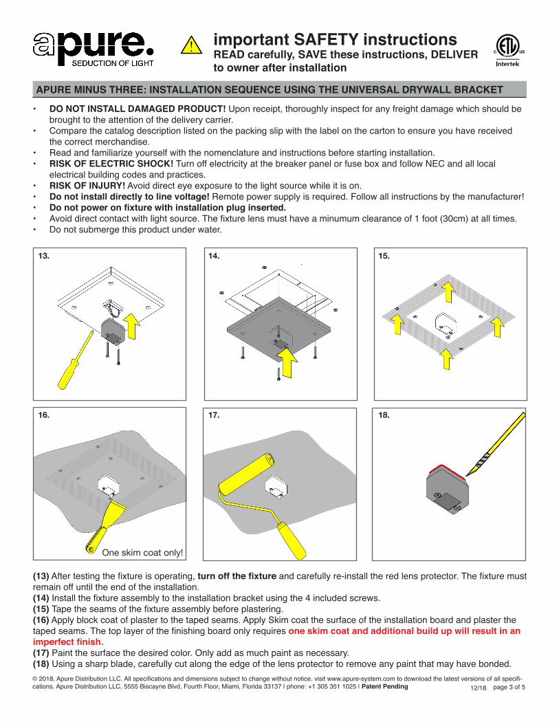
(13) After testing the fixture is operating, turn off the fixture and carefully re-install the red lens protector. The fixture must remain off until the end of the installation.(14) Install the fixture assembly to the installation bracket using the 4 included screws. (15) Tape the seams of the fixture assembly before plastering. (16) Apply block coat of plaster to the taped seams. Apply Skim coat the surface of the installation board and plaster the taped seams. The top layer of the finishing board only requires one skim coat and additional build up will result in an imperfect finish.(17) Paint the surface the desired color. Only add as much paint as necessary.(18) Using a sharp blade, carefully cut along the edge of the lens protector to remove any paint that may have bonded.
13. 14. 15.
16. 17. 18.
One skim coat only!

Failure to follow any of these instructions could void product warranties. For a complete listing of product Terms and Conditions, please visit www.apure-system.com. Apure assumes no responsibility for claims arising out of improper or careless installation or handling of its products.
important SAFETY instructionsREAD carefully, SAVE these instructions, DELIVER to owner after installation
APURE MINUS THREE: INSTALLATION SEQUENCE USING THE UNIVERSAL DRYWALL BRACKET
THESE INSTRUCTIONS DO NOT PURPORT TO COVER ALL DETAILS OR VARIATIONS IN EQUIPMENT NOR TO PROVIDE FOR EVERY POSSIBLE CONTINGENCY TO BE MET IN CONNECTION WITH INSTALLATION, OPERATION OR MAINTENANCE. SHOULD FURTHER INFORMATION BE DESIRED OR SHOULD PARTICULAR PROBLEMS ARISE WHICH ARE NOT COVERED SUFFICIENTLY FOR THE CUSTOMER/OPERATOR‘S PURPOSES THE MATTER SHOULD BE REFERRED TO APURE DISTRIBUTION, LLC
• DO NOT INSTALL DAMAGED PRODUCT! Upon receipt, thoroughly inspect for any freight damage which should be brought to the attention of the delivery carrier.
• Compare the catalog description listed on the packing slip with the label on the carton to ensure you have received the correct merchandise.
• Read and familiarize yourself with the nomenclature and instructions before starting installation.• RISK OF ELECTRIC SHOCK! Turn off electricity at the breaker panel or fuse box and follow NEC and all local
electrical building codes and practices. • RISK OF INJURY! Avoid direct eye exposure to the light source while it is on.• Do not install directly to line voltage! Remote power supply is required. Follow all instructions by the manufacturer!• Do not power on fixture with installation plug inserted.• Avoid direct contact with light source. The fixture lens must have a minumum clearance of 1 foot (30cm) at all times.• Do not submerge this product under water.
(19) Carefully unscrew and remove the protector from the fixture assembly. (20) Gently attach the Minus 3 lens cover. The lens cover is magnetic and snaps to the base of the fixture. (21) The installation is now complete.
19. 20. 21.
© 2018. Apure Distribution LLC. All specifications and dimensions subject to change without notice. visit www.apure-system.com to download the latest versions of all specifi-cations. Apure Distribution LLC, 5555 Biscayne Blvd, Fourth Floor, Miami, Florida 33137 | phone: +1 305 351 1025 | Patent Pending 12/18 page 4 of 5

Failure to follow any of these instructions could void product warranties. For a complete listing of product Terms and Conditions, please visit: www.apure-system.com. Apure assumes no responsibility for claims arising out of improper or careless installation or handling of its products.
important SAFETY instructionsREAD carefully, SAVE these instructions, DELIVER to owner after installation
APURE MINUS THREE: INSTALLATION SEQUENCE USING THE UNIVERSAL DRYWALL BRACKET
THESE INSTRUCTIONS DO NOT PURPORT TO COVER ALL DETAILS OR VARIATIONS IN EQUIPMENT NOR TO PROVIDE FOR EVERY POSSIBLE CONTINGENCY TO BE MET IN CONNECTION WITH INSTALLATION, OPERATION OR MAINTENANCE. SHOULD FURTHER INFORMATION BE DESIRED OR SHOULD PARTICULAR PROBLEMS ARISE WHICH ARE NOT COVERED SUFFICIENTLY FOR THE CUSTOMER/OPERATOR‘S PURPOSES THE MATTER SHOULD BE REFERRED TO APURE DISTRIBUTION, LLC
© 2018. Apure Distribution LLC. all specifications and dimensions subject to change without notice. visit www.apure-system.com to download the latest versions of all specifications. apure distribution LLC, 5555 Biscayne Blvd, Fourth Floor, Miami, Florida 33137 | phone: +1 305 351 1025 | Patent Pending 12/18 page 5 of 5
• DO NOT INSTALL DAMAGED PRODUCT! Upon receipt, thoroughly inspect for any freight damage which should be brought to the attention of the delivery carrier.
• Compare the catalog description listed on the packing slip with the label on the carton to ensure you have received the correct merchandise.
• Read and familiarize yourself with the nomenclature and instructions before starting installation.• RISK OF ELECTRIC SHOCK! Turn off electricity at the breaker panel or fuse box and follow NEC and all local electrical
building codes and practices. • RISK OF INJURY! Avoid direct eye exposure to the light source while it is on.• Do not install directly to line voltage! Remote power supply is required. Follow all instructions supplied by the manufacturer!• Do not power on fixture with installation plug inserted.• Avoid direct contact with light source. Aperture must have a minumum clearance of 1 foot (30cm) at all times.• Do not submerge this product under water. • Be sure to keep the aperture of the fixture dust free.
schwarz
rot weiss
schwarz
rot weiss
schwarz
rot weiss
schwarz
rot
schwarz
rot weiss
schwarz
rot weiss
schwarz
rot weiss
schwarz
rot weiss
MINUS* MINUS MINUS MINUS
24V REMOTEPOWER SUPPLY
LINE
NEUTRAL
GROUND
DIMMER / MODULE
+24VDC
-24VDC
*up to 5 fixtures, power supply specific
PHASENDIMMER
MINUS MINUSMINUS* MINUS MINUS
AA3-2205-D-EUNETZTEIL
ACHTUNG!Netzteil mit mind. drei Leuchten betreiben! Ein Betrieb mit weniger als drei Leuchten führt zur Zerstörung von Netzteil und Leuchte!
Das weiße und schwarze Kabel der letzten Leuchte muss immer mit einer Brücke versehen werden (ist im Lieferumfang enthalten/ schon montiert)
mind. 3 Leuchten betreiben
LEITER PHASE (SCHWARZ)
LEITER NEUTRAL (BLAU)
LEITER ERDUNG (GRUEN/GELB)
DALI / 0-10V / PUSH
MINUS MINUSMINUS MINUS
AA3-DALI-D-EUNETZTEIL
LEITER PHASE (SCHWARZ)
LEITER NEUTRAL (BLAU)
LEITER ERDUNG (GRUEN/GELB)
PHASENDIMMER
MINUS MINUS
AA3-2202-D-EUNETZTEIL
LEITER PHASE (SCHWARZ)
LEITER NEUTRAL (BLAU)
LEITER ERDUNG (GRUEN/GELB)
schwarz
rot weiss
schwarz
rot
schwarz
rot
Das weiße und schwarze Kabel der letzten Leuchte muss immer mit einer Brücke versehen werden (ist im Lieferumfang enthalten/ schon montiert)
Das weiße und schwarze Kabel der letzten Leuchte muss immer mit einer Brücke versehen werden (ist im Lieferumfang enthalten/ schon montiert)
MINUS
Minus Series Wiring Diagram• Minus fixtures are to be wired to the power supply using min. 16AWG cable via parallel wiring.• Operation of up to 4 fixtures per AA3-100-L (96W) power supply.• Operation of up to 5 fixtures per Lutron (L3D0-96W24V-U) driver. • Follow all instructions supplied by power supply / driver manufactuer!• Before any mudding, finishing or painting - test that all fixtures are functioning properly!
Fixture LeadsWhite (+)Black (-)