1 2, 3 , han gao 2 and yonghui lin - mdpi
TRANSCRIPT
materials
Article
Resistance of Soda Residue–Fly Ash Based Geopolymer Mortarto Acid and Sulfate Environments
Xianhui Zhao 1 , Haoyu Wang 2,* , Boyu Zhou 3 , Han Gao 2 and Yonghui Lin 3,4
�����������������
Citation: Zhao, X.; Wang, H.; Zhou,
B.; Gao, H.; Lin, Y. Resistance of Soda
Residue–Fly Ash Based Geopolymer
Mortar to Acid and Sulfate
Environments. Materials 2021, 14, 785.
https://doi.org/10.3390/ma14040785
Academic Editor: Luigi Coppola
Received: 13 January 2021
Accepted: 4 February 2021
Published: 7 February 2021
Publisher’s Note: MDPI stays neutral
with regard to jurisdictional claims in
published maps and institutional affil-
iations.
Copyright: © 2021 by the authors.
Licensee MDPI, Basel, Switzerland.
This article is an open access article
distributed under the terms and
conditions of the Creative Commons
Attribution (CC BY) license (https://
creativecommons.org/licenses/by/
4.0/).
1 School of Civil Engineering, Hebei University of Engineering, Handan 056038, China;[email protected]
2 Tianjin University Renai College, Tianjin 301636, China; [email protected] School of Civil and Transportation Engineering, Hebei University of Technology, Tianjin 300401, China;
[email protected] (B.Z.); [email protected] (Y.L.)4 Department of Economics and Management, Hebei Normal University for Nationalities,
Chengde 067000, China* Correspondence: [email protected]
Abstract: The early mechanical performances of low-calcium fly ash (FFA)-based geopolymer (FFA–GEO) mortar can be enhanced by soda residue (SR). However, the resistance of SR–FFA–GEOmortar to acid or sulfate environments is unclear, owing to the various inorganic calcium salts inSR. The aim of this study was to investigate the long-term mechanical strengths of up to 360 d andevaluate the resistance of SR–FFA–GEO mortar to 5% HCl and 5% Na2SO4 environments through thelosses in compressive strength and mass. Scanning Electron Microscopy (SEM), Energy-DispersiveSpectroscopy (EDS) and Fourier Transform Infrared Spectrometer (FTIR) experiments were conductedfor the SR–FFA–GEO mortars, both before and after chemical attack, to clarify the attack mechanism.The results show that the resistances of the SR–FFA–GEO mortar with 20% SR (namely M10) to5% HCl and 5% Na2SO4 environments are superior to those of cement mortar. The environmentalHCl reacts with the calcites in SR to produce CaCl2, CO2 and H2O to form more pores under HClattack, and the environmental Na+ cations from Na2SO4 go into Si-O-Al network structure, to furtherenhance the strength of mortar under Na2SO4 attack. These results provide the experimental basisfor the durability optimization of SR–FFA–GEO mortars.
Keywords: geopolymer; fly ash; soda residue; chemical attack; compressive strength; microstructure
1. Introduction
In recent years, geopolymer material has obtained rapid development and wideinterest in the industry of building material [1,2]. As the sustainable alternatives to con-ventional cement, geopolymer material has the potential for reducing energy consump-tion and CO2 emission by approximately 60% and 80%, respectively [3–5]. As a kindof alkali-activated aluminosilicates, geopolymer material possesses similar (or superior)mechanical properties to Ordinary Portland Cement (OPC)-based material, as well asdurable performances, such as high compressive strength, high compatibility with organiccomponents [6], high hardness, high thermal-stability, high fire-resistance, high chemicalerosion-resistance, etc. [7–10]. Currently, some industrial solid wastes composed of alumi-nosilicate phases, such as fly ash (FA), blast furnace slag, red mud, etc., can be employed forpreparing geopolymer products by alkali-activation [8,11,12]. In particular, the reutilizationof available industrial solid wastes is of great significance to the international ecologicalenvironment.
Low-calcium fly ash (FFA), as one of most commonly used raw materials and mostavailable solid wastes for geopolymer preparation, mainly consists of amorphous spheri-cal beads with aluminosilicate compositions [2,13–15]. The amorphous geopolymer canbe manufactured with FFA and basic alkaline solution with Na+ or K+ cations, such as
Materials 2021, 14, 785. https://doi.org/10.3390/ma14040785 https://www.mdpi.com/journal/materials
Materials 2021, 14, 785 2 of 19
NaOH, KOH, Na2SiO3 or other mixed solutions by geopolymerization process [13,16,17].Moreover, the sodium-aluminosilicate-polymer gel (N-A-S-H) has been verified through aseries of micro-structural detection experiments [18,19]. Moreover, evenly applied N-A-S-H gel with strong chemical bond energy of Si-O-Al chains makes geopolymer materialpossess good mechanical strength and superior durability [2,12,18]. However, the FFAs areactivated by alkaline solutions, at room or ambient temperatures, due to the incomplete dis-solution, as well as the slow hardening rate, presenting the disadvantages of longer settingtime, along with slower strength development, and evenly performing that the unconfinedcompressive strengths at a 28-day age are lower than 10 MPa [17,20,21]. Additionally,Zhao et al. [22] prepared the fly ash–geopolymer cement incorporating soda residue bypress-form method. It was revealed that the alkali-activated geopolymer was synthesizedfrom fly ash and soda residue (mass ratio is 1:1) activated by 5% NaOH, which obtains thecompressive strength of 22.04 MPa. In particular, the FFA–GEO materials are limited to theprecast structure members [23,24] and the backfill materials [22,25]. However, the previousstudies have presented that additional calcium source and temperature-curing are tworelatively effective external ways to improve the fresh and mechanical performances ofFFA–GEO materials [25–28]. The long pre-curing at room temperature (25 ◦C) is beneficialfor the compressive strength enhancement of FFA–GEO before cured at elevated tempera-ture [19]. For the long-term mechanical strength, FFA–GEO was recommended to cure atroom temperature, with sealed treatment to obtain higher compressive strength of up to180 d [27]. On the other hand, some calcium-additives, such as CaO, Ca(OH)2 and CaCO3,produce the positive influence on the mechanical properties and the microstructure ofFFA–GEO material [29–31].
Soda residue (SR), as one of most available chemical industry solid wastes in China,is mainly composed of various inorganic calcium salts—64% CaCO3, 10% Ca(OH)2, 6%CaCl2 and 3% CaSO4 [27]. The SRs are the by-product of the industrial Na2CO3 process,and 7.8~10.0 million tons of SRs are produced annually by more than 50 enterprises inChina [32,33]. To achieve the recycling reutilization of the SR, the SR was used as a calciumadditive in alkali-activated FFA materials, to prepare geopolymer at room or ambienttemperature [22,25,27,28].
In the previous research, it was revealed that the press-formed preparation of alkali-activated fly ash cement reusing the SR (particle size < 2.0 mm), the FFA and 5.0% NaOHmixed with 0.518 liquid–solid ratio (L/S) was feasible as the brick or soil materials [22].The compressive strength of the designed sample (with the extremely low water absorptionof 2.65%) reached 22.04 MPa at 90 d. Owing to the addition of the SR, the final gel productswere the mixtures of geopolymeric gels (N,C)-A-S-H and hydrated gels (C-A-S-H and/orC-S-H) at 90 d, by the detections of SEM–EDS, XRD and FTIR tests. Moreover, the SRwas reutilized as a calcium source in FFA–GEO as the goaf backfill material alternative tocement-based material [25]. Furthermore, it was feasible for the SR to improve and enhancethe fresh and mechanical performances of FFA–GEO backfill pastes at room temperature.The optimal paste SFN6 (SR–FA ratio 2:3, solution concentration 2.0 mol/L and L/S 1.2)obtained high fluidity (260.0 mm), better compressive strength (3.70 MPa), as well as highstone ratio (98.6%) for grouting backfill. The gel products of SFN6 were clarified as themixtures of (N,C)-A-S-H and C-S-H gels. In addition, the geopolymer cement mortarswere prepared by casting method, using SR, FFA and NaOH solution as the alternative tocement products, due to the superior mechanical strength, micro-characteristic and thermalstability [27]. The flexural and compressive strengths of prepared mortars all increasedwith the additional content of the SR from 0 to 120 g at 60 days old. The curing time of upto 180 d was investigated, and it was found that SR just played a role in the enhancementof early term compressive strength. However, the long-term mechanical performanceof up to 360 d is still unclear for soda residue–low-calcium-fly-ash-based geopolymer(SR–FFA–GEO). It is conducive to evaluate the stability and durability of SR–FFA–GEOcement material at long curing ages.
Materials 2021, 14, 785 3 of 19
Additionally, the durability and stability of SR–FFA–GEO material are closely relatedwith the gel products and microstructures [27,28]. Moreover, the gel product compositionsare determined by the additional contents of calcium sources for alkali-activated FFAmaterials [26]. The additional calcium-source makes FFA–GEO form (N,C)-A-S-H or thecoexistence of C-S-H and N-A-S-H, but the main gel products will be C-S-H and C-A-S-Hwith the excessive calcium-additives [29]. In particular, the mechanical performances andmicro-characteristics were investigated for SR–FFA–GEO cement as building material inthe previous study [27], and however, the resistance of SR–FFA–GEO material to chemicalattack is still unclear owing to the various inorganic calcium-containing salts. In theaggressive environments of mining, chemical, mineral processing and other industries,the acid and sulfate attack are the desirable performances for the building materials [34].Therefore, the resistances of SR–FFA–GEO material to acid and sulfate environmentsshould be further explored to supplement the durability of geopolymer materials, guidethe optimization in mixing proportion for the larger scale and promote the wider utilizationof cleaner productions.
The main aim of this research is to investigate the long-term strength developments ofSR–FFA–GEO mortar cured for up to 360 d, and then evaluate the resistances of SR–FFA–GEO mortar to 5% hydrochloric acid (HCl) and 5% sodium sulfate (Na2SO4) environmentsthrough compressive strength loss and mass loss. Furthermore, the reaction mechanismsof HCl and Na2SO4 attack were investigated through the detections of SEM, EDS and FTIRtests. The results will provide the references for the properties’ optimization and the widerreuse of the SR and the FFA to a larger scale.
2. Materials and Methods2.1. Raw Materials
The raw materials for preparing geopolymer (GEO) mortars are low-calcium-fly-ash(FFA) powder (Powder Company, Nanning, China), soda-residue (SR) powder (SanyouCompany, Tangshan, China), fine-aggregate (standard sand) and alkali-activator (sodiumhydroxide solution) (Kemiou Company, Tianjin, China). The basic chemical components ofFFA and SR are presented by XRF in Table 1, and the physical indexes of the FFA and theSR are shown in Table 2. Moreover, the SEM images and the XRD patterns of raw materialsFFA and SR are referenced in the previous studies [22,25,27].
Table 1. Chemical compositions of solid powders by XRF.
Materials Chemical Composites and Mass Percentages 1
Soda residue (SR) CaCO3 Ca(OH)2 CaCl2 CaSO4 NaCl SiO2 Al2O3 Acid InsolublePercentage (%) 64.0 10.0 6.0 3.0 4.0 3.0 2.0 8.0
Low-calcium fly ash (FFA) SiO2 Al2O3 Fe2O3 CaO FeO MgO LOI 2 OthersPercentage (%) 51.20 25.32 7.80 5.32 2.20 1.80 3.05 3.31
1 Data from the literature by Zhao et al. [27]. 2 LOI refers to the loss on ignition at the temperature of 1000 ◦C (%).
Table 2. Physical indexes of raw material SR and FFA.
SolidPowders
SpecificSurface
Area (m2/kg)
pH Valueat w100
1
AmountPassing
#325 Sieve
MeanParticle
Size (mm)
SpecificGravity 2
SR — 8.35 24% 0.25 2.35FFA 510 5.90 76% — 2.44
1 w100 refers to the measured pH at 100% of water content under room temperature. 2 Data from the literature byZhao et al. [27].
The low-calcium fly ash (FFA) includes 5.32% of active CaO, which is supported by apower plant in Jiangxi Province, Southern China. From the SEM images, the FFA mainlyconsists of the micro-beads with the powerful potential-reactivity that have a slightlysmooth surface, as described by Zhao et al. [22,25,27]. For the XRD pattern, the FFA is
Materials 2021, 14, 785 4 of 19
essentially composed of 25.32% Al2O3 and 51.20% SiO2; the crystal components of FFAcontain mullite and quartz, while the “hump” of amorphous phases (vitreous) is in therange from 19◦ 2θ to 29◦ 2θ in the XRD pattern [27].
The soda residue (SR) includes nearly 83% of the inorganic calcium-containing salts -CaCO3, CaCl2 and Ca(OH)2, as well as CaSO4, which is derived from a Na2CO3-productionplant in Hebei province, Northern China [22,25,27]. From the SEM picture, the SR possessesporous and loose microstructural morphology, as described by Zhao et al. [27]. From theXRD pattern, the SR consists of halite (NaCl), gypsum (CaSO4) and calcite (CaCO3) crystalphases. After dried at 40 ◦C, the SR was first milled and then sieved for 0.5 mm (the particlesize ≤ 0.5 mm, and amount passing #325 sieve is 24%), for sample preparation.
Standard stand meets the standards of GB/T 17671-1999 (ISO) [35]. The square holelengths to the cumulative screening-quality percentage are exactly identical with that usedin the previous study [27]. Moreover, the loss on ignition (LOI) is less than 0.40%, SiO2content is high than 98%, as well as mud content (including soluble salts) is less than 0.20%.
Alkali-activator: The sodium hydroxide (NaOH) solution was prepared by dissolvingNaOH pellets (purity ≥ 98% and analytical grade) into the distilled water. In general,the 8~14 mol/L molarity concentration of NaOH solution is used to prepare geopolymersamples for the better alkali-activated effects [18,36]. Moreover, considering the economicbenefits, in this study, NaOH solution with 8 mol/L concentration was utilized as the alka-line activator. The alkali-activator was cooled to 25 ± 2 ◦C before sample preparation [27].
Acid and sulfate attack solutions: The 5% hydrochloric acid (HCl) and 5% sodiumsulfate (Na2SO4) solutions were selected to conduct the acid and sulfate attack experiments,for the comparison with the data in References [26,37]. All of the utilized chemical solutionswere derived from Baishi company in Tianjin, China.
2.2. Preparation of Geopolymer Mortars
The SR–FFA–GEO geopolymer mortars were prepared, using SR powder, FFA powderand NaOH solution. The SR and FFA are used as the precursors for preparing geopolymer.In this work, ten groups of geopolymer mortars were manufactured with the liquid–solidratio (L/S) of 0.75, as shown in Table 3. Here, L/S means the mass ratio of alkali-activatorNaOH solution to solid powders (SR and FFA), and cement–sand ratio (C/S) means themass ratio of solid powders to standard sands. The costs of each group are identical due tothe same L/S and the identical contents of the solid powders.
Table 3. Mixing proportions of the geopolymer mortars prepared at room temperature. Liquid–solidratio is 0.75, and cement–sand ratio is 1:3.
No. FFA(g)
SR(g)
SRContent
StandardStand (g)
NaOH Solution(mol/L)
Na/SiRatio
Al/SiRatio
Ca/SiRatio
M 1 450 0 0.0% 1350 8 0.54 0.57 0.11M 2 440 10 2.2% 1350 8 0.55 0.57 0.12M 3 430 20 4.4% 1350 8 0.57 0.57 0.12M 4 420 30 6.7% 1350 8 0.58 0.57 0.13M 5 410 40 8.9% 1350 8 0.59 0.57 0.13M 6 400 50 11.1% 1350 8 0.61 0.57 0.14M 7 390 60 13.3% 1350 8 0.63 0.57 0.15M 8 380 70 15.6% 1350 8 0.64 0.57 0.15M 9 370 80 17.8% 1350 8 0.66 0.57 0.16M10 360 90 20.0% 1350 8 0.68 0.57 0.17
Note: Na/Si ratio refers to the molar ratio of Na from NaOH to Si from SiO2. Al/Si ratio refers to the molarratio of Al from Al2O3 to Si from SiO2. Ca/Si ratio refers to the molar ratio of Ca from CaCl2, CaSO4, CaO andCa(OH)2 to Si from SiO2.
The solid powders (both of SR and FFA) were firstly blended for three minutes, andthen 8 mol/L NaOH solution (25.10% NaOH + 74.90% H2O) was mixed with solid powdersand stirred for another five minutes, according to Reference [27]. Thereafter, standard sand
Materials 2021, 14, 785 5 of 19
was added, and then evenly stirred for another ten minutes, to get the fresh mixtures. Afterthe stirring, the fresh mixtures were casted into the prismatic steel molds (the size of 40 mm× 40 mm × 160 mm) by two layers, according to the Chinese standard GB/T 17671-1999(ISO) [35]. Each layer of the fresh mixtures was vibrated for another two minutes on thevibrating table. In particular, the size of steel molds 40 mm × 40 mm × 160 mm wasselected to compare the testing results with that in the previous literature [27,37].
To research the influence of long curing-age up to 360 d on the mechanical strengthdevelopment of mortar samples, the geopolymer mortar samples were manufacturedwith the different SR contents (Table 3). Here, the mortar samples were designed tocure respectively for 90, 150 and 360 d, at room temperature (25 ± 3 ◦C), after beingsealed with the plastic films; the curing method of was recommended in the previousstudy [27]. The prepared mortar samples were demolded after being cured for 60 d, due tothe slow hardening at room temperature [38]. Based on the hardening effect, the selectionof 60 days to demold is also to reduce the influence of steel mold on the late shrinkage ofthe geopolymer mortar. After demolded, the original curing condition was continued untilthe required ages.
2.3. Testing Methods2.3.1. Determination of Fresh and Physical Properties
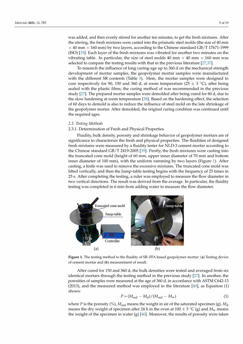
Fluidity, bulk density, porosity and shrinkage behavior of geopolymer mortars are ofsignificance to characterize the fresh and physical properties. The fluidities of designedfresh mixtures were measured by a fluidity tester for NLD-3 cement mortar according tothe Chinese standard GB/T 2419-2005 [39]. Firstly, the fresh mixtures were casting intothe truncated cone mold (height of 60 mm, upper inner diameter of 70 mm and bottominner diameter of 100 mm), with the uniform ramming by two layers (Figure 1). Aftercasting, a knife was used to remove the excessive mixtures. The truncated cone mold waslifted vertically, and then the Jump-table testing begins with the frequency of 25 times in25 s. After completing the testing, a ruler was employed to measure the flow diameter intwo vertical directions. The result was derived from the average. In particular, the fluiditytesting was completed in 6 min from adding water to measure the flow diameter.
Materials 2021, 14, x FOR PEER REVIEW 5 of 19
prepared mortar samples were demolded after being cured for 60 d, due to the slow hard-ening at room temperature [38]. Based on the hardening effect, the selection of 60 days to demold is also to reduce the influence of steel mold on the late shrinkage of the geopoly-mer mortar. After demolded, the original curing condition was continued until the re-quired ages.
Table 3. Mixing proportions of the geopolymer mortars prepared at room temperature. Liquid–solid ratio is 0.75, and cement–sand ratio is 1:3.
No. FFA (g)
SR (g)
SR Content
Standard Stand (g)
NaOH Solution (mol/L)
Na/Si Ratio
Al/Si Ratio
Ca/Si Ratio
M 1 450 0 0.0% 1350 8 0.54 0.57 0.11 M 2 440 10 2.2% 1350 8 0.55 0.57 0.12 M 3 430 20 4.4% 1350 8 0.57 0.57 0.12 M 4 420 30 6.7% 1350 8 0.58 0.57 0.13 M 5 410 40 8.9% 1350 8 0.59 0.57 0.13 M 6 400 50 11.1% 1350 8 0.61 0.57 0.14 M 7 390 60 13.3% 1350 8 0.63 0.57 0.15 M 8 380 70 15.6% 1350 8 0.64 0.57 0.15 M 9 370 80 17.8% 1350 8 0.66 0.57 0.16 M10 360 90 20.0% 1350 8 0.68 0.57 0.17
Note: Na/Si ratio refers to the molar ratio of Na from NaOH to Si from SiO2. Al/Si ratio refers to the molar ratio of Al from Al2O3 to Si from SiO2. Ca/Si ratio refers to the molar ratio of Ca from CaCl2, CaSO4, CaO and Ca(OH)2 to Si from SiO2.
2.3. Testing Methods 2.3.1. Determination of Fresh and Physical Properties
Fluidity, bulk density, porosity and shrinkage behavior of geopolymer mortars are of significance to characterize the fresh and physical properties. The fluidities of designed fresh mixtures were measured by a fluidity tester for NLD-3 cement mortar according to the Chinese standard GB/T 2419-2005 [39]. Firstly, the fresh mixtures were casting into the truncated cone mold (height of 60 mm, upper inner diameter of 70 mm and bottom inner diameter of 100 mm), with the uniform ramming by two layers (Figure 1). After casting, a knife was used to remove the excessive mixtures. The truncated cone mold was lifted ver-tically, and then the Jump-table testing begins with the frequency of 25 times in 25 s. After completing the testing, a ruler was employed to measure the flow diameter in two vertical directions. The result was derived from the average. In particular, the fluidity testing was completed in 6 min from adding water to measure the flow diameter.
(a) (b)
Figure 1. The testing method to the fluidity of SR–FFA based geopolymer mortar: (a) Testing de-vice of cement mortar and (b) measurement of result.
After cured for 150 and 360 d, the bulk densities were tested and averaged from six identical mortars through the testing method in the previous study [27]. In another, the
Figure 1. The testing method to the fluidity of SR–FFA based geopolymer mortar: (a) Testing deviceof cement mortar and (b) measurement of result.
After cured for 150 and 360 d, the bulk densities were tested and averaged from sixidentical mortars through the testing method in the previous study [27]. In another, theporosities of samples were measured at the age of 360 d, in accordance with ASTM C642-13(2013), and the measured method was employed in the literature [40], as Equation (1)shows:
P = (Mssd −Md)/(Mssd −Mw) (1)
where P is the porosity (%), Mssd means the weight in air of the saturated specimen (g), Mdmeans the dry weight of specimen after 24 h in the oven at 100 ± 5 ◦C (g) and Mw meansthe weight of the specimen in water (g) [40]. Moreover, the results of porosity were taken
Materials 2021, 14, 785 6 of 19
from the average of six identical mortars. To observe the shrinkage behaviors of preparedmortar, the side height values of mortars at the age of 90 and 360 d were recorded by acaliper (resolution is 0.02 mm), according to the previous study [27]. The shrinkage dataare specified as the average casting height of hardening samples to the side of the adoptedmold (initial casting height 40.0 mm without shrinkage).
2.3.2. Determination of Long-Term Mechanical Properties
At the designed curing ages of 90, 180, 270 and 360 d, the flexural and compressivestrengths were measured, using a servo-control testing machine (YAW-S, Sansi Zongheng,Shenzhen, China) with the loading capacity of 300 kN, with the accordance of GB/T17671-1999 (ISO). According to the standard, the loading rates were, respectively, 2400 and50 N/s for compressive and flexural strength tests [27]. The results were averaged from sixidentical mortar samples.
2.3.3. Characterization of Acid and Sulfate Attack
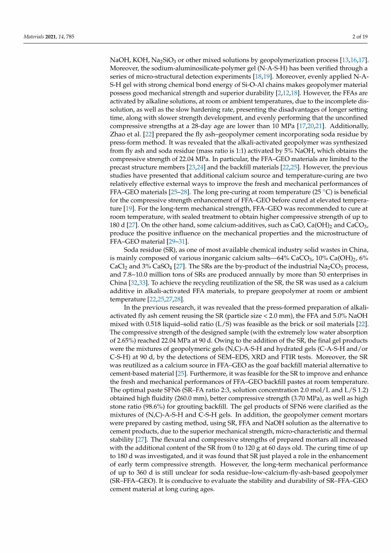
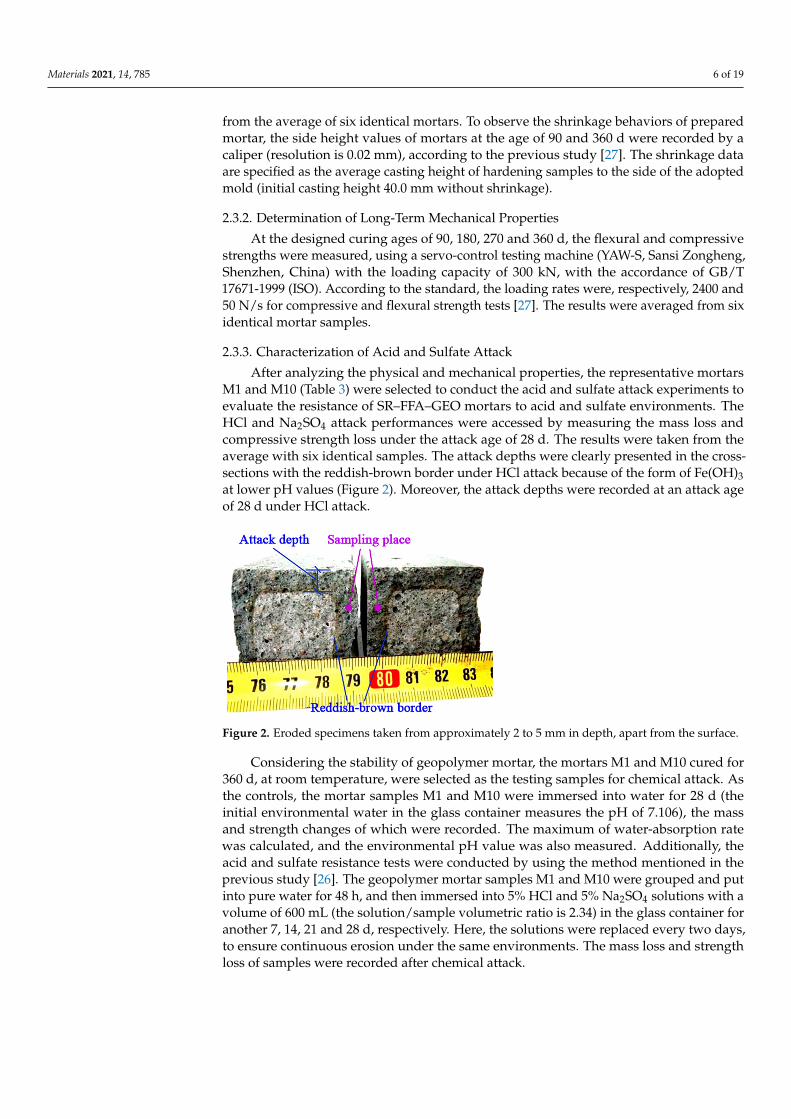
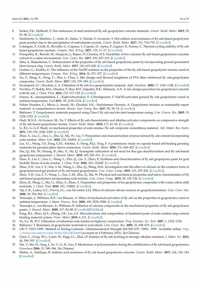
After analyzing the physical and mechanical properties, the representative mortarsM1 and M10 (Table 3) were selected to conduct the acid and sulfate attack experiments toevaluate the resistance of SR–FFA–GEO mortars to acid and sulfate environments. TheHCl and Na2SO4 attack performances were accessed by measuring the mass loss andcompressive strength loss under the attack age of 28 d. The results were taken from theaverage with six identical samples. The attack depths were clearly presented in the cross-sections with the reddish-brown border under HCl attack because of the form of Fe(OH)3at lower pH values (Figure 2). Moreover, the attack depths were recorded at an attack ageof 28 d under HCl attack.
Materials 2021, 14, x FOR PEER REVIEW 7 of 19
Figure 2. Eroded specimens taken from approximately 2 to 5 mm in depth, apart from the surface.
The microstructures and gel compositions were detected through SEM–EDS tests. The mortar M10 with 20% SR contents, both before and after HCl and Na2SO4 attack, were investigated for the morphology and elemental components of gel products. A scanning electron microscope (SEM, Quanta FEG450, Hillsboro, OR, USA), coupled with an energy dispersive spectroscopy (EDS), was utilized [25,27,28].
Furthermore, the FTIR tests were conducted to characterize the products after chem-ical attack by the characteristic peak of the chemical bonds. The mortar M10 before and after HCl and Na2SO4 attack was detected. The specimens (first air-dried for 48 h and then milled) were weighed 1.3 ± 0.001 mg with 130 mg KBr pellets, to manufacture the tested specimens. A transformation infrared spectroscopy (FTIR, Nexus 8, Bruker, Karlsruhe, German) was used to detect the FTIR spectra with the wavenumber 400~3750 cm−1 [25,27,28].
3. Results and Discussion 3.1. Long-Term Physical Properties of SR–FFA–GEO Mortars
The fresh and physical properties of SR–FFA–GEO at 90, 150 and 360 d were shown in Table 4 and Table 5, including fluidity, bulk density, porosity and the shrinkage behav-ior in height.
The fluidities of the fresh geopolymer mortars were measured to elaborate the work-ability (Table 4). The fluidities decrease with the addition of SR from 0% to 20% (refined as SR increment of 2.2%). Moreover, the fluidity of M10 (with 20% SR) is 20.1% lower than that of M1 (without SR). This may result from the physical water absorption of SR [27], which is further evidence of the workability properties of SR–FFA–GEO materials.
Additionally, the bulk densities, mentioned in the previous research [27], were tested to further investigate the influence of SR on the density of the geopolymer mortar under long-term curing (Table 4). The bulk densities of 150 and 360 d all decrease with the in-crease of SR. But there are extremely small differences in bulk densities, which mainly results from the lower specific gravity of pure SR (2.35) than that of pure FFA (2.44). More-over, the 360-day-old bulk densities are about 0.05%~0.19% lower than that of 150 days of age, which results from the moisture loss of mortars under long-term curing. This small changing trend is consistent with the previous results tested by Zhao et al. [27].
Table 4. The fluidity and bulk density of the geopolymer mortars with different SR contents cured for 150 and 360 d, at room temperature.
No. SR
Content Fluidity
(mm) Bulk Density (g/cm3) Difference Percentage
for 150~360 d 150 d 1 Difference 360 d Difference M 1 0.0% 184 2.145 ±0.017 2.143 ±0.015 0.09% M 2 2.2% 181 2.135 ±0.015 2.134 ±0.013 0.05% M 3 4.4% 176 2.123 ±0.023 2.12 ±0.020 0.14% M 4 6.7% 171 2.117 ±0.016 2.115 ±0.014 0.09% M 5 8.9% 164 2.113 ±0.020 2.111 ±0.022 0.09%
Figure 2. Eroded specimens taken from approximately 2 to 5 mm in depth, apart from the surface.
Considering the stability of geopolymer mortar, the mortars M1 and M10 cured for360 d, at room temperature, were selected as the testing samples for chemical attack. Asthe controls, the mortar samples M1 and M10 were immersed into water for 28 d (theinitial environmental water in the glass container measures the pH of 7.106), the massand strength changes of which were recorded. The maximum of water-absorption ratewas calculated, and the environmental pH value was also measured. Additionally, theacid and sulfate resistance tests were conducted by using the method mentioned in theprevious study [26]. The geopolymer mortar samples M1 and M10 were grouped and putinto pure water for 48 h, and then immersed into 5% HCl and 5% Na2SO4 solutions with avolume of 600 mL (the solution/sample volumetric ratio is 2.34) in the glass container foranother 7, 14, 21 and 28 d, respectively. Here, the solutions were replaced every two days,to ensure continuous erosion under the same environments. The mass loss and strengthloss of samples were recorded after chemical attack.
Materials 2021, 14, 785 7 of 19
2.3.4. Investigation into Attack Mechanisms through SEM–EDS and FTIR
After the acid and sulfate attack tests, the attack mechanisms of the SR–FFA–GEOmortar cured for 360 d are further detected, which helps to give a suggestion of durabil-ity and stability optimization. Eroded specimens of 28-day attack age were taken fromapproximately 2 to 5 mm in depth, apart from the outer surface (Figure 2).
The microstructures and gel compositions were detected through SEM–EDS tests. Themortar M10 with 20% SR contents, both before and after HCl and Na2SO4 attack, wereinvestigated for the morphology and elemental components of gel products. A scanningelectron microscope (SEM, Quanta FEG450, Hillsboro, OR, USA), coupled with an energydispersive spectroscopy (EDS), was utilized [25,27,28].
Furthermore, the FTIR tests were conducted to characterize the products after chem-ical attack by the characteristic peak of the chemical bonds. The mortar M10 before andafter HCl and Na2SO4 attack was detected. The specimens (first air-dried for 48 h and thenmilled) were weighed 1.3 ± 0.001 mg with 130 mg KBr pellets, to manufacture the testedspecimens. A transformation infrared spectroscopy (FTIR, Nexus 8, Bruker, Karlsruhe, Ger-man) was used to detect the FTIR spectra with the wavenumber 400~3750 cm−1 [25,27,28].
3. Results and Discussion3.1. Long-Term Physical Properties of SR–FFA–GEO Mortars
The fresh and physical properties of SR–FFA–GEO at 90, 150 and 360 d were shownin Tables 4 and 5, including fluidity, bulk density, porosity and the shrinkage behavior inheight.
Table 4. The fluidity and bulk density of the geopolymer mortars with different SR contents curedfor 150 and 360 d, at room temperature.
No. SRContent
Fluidity(mm)
Bulk Density (g/cm3) Difference Percentagefor 150~360 d150 d 1 Difference 360 d Difference
M 1 0.0% 184 2.145 ±0.017 2.143 ±0.015 0.09%M 2 2.2% 181 2.135 ±0.015 2.134 ±0.013 0.05%M 3 4.4% 176 2.123 ±0.023 2.12 ±0.020 0.14%M 4 6.7% 171 2.117 ±0.016 2.115 ±0.014 0.09%M 5 8.9% 164 2.113 ±0.020 2.111 ±0.022 0.09%M 6 11.1% 158 2.107 ±0.015 2.104 ±0.017 0.14%M 7 13.3% 153 2.104 ±0.025 2.101 ±0.023 0.14%M 8 15.6% 152 2.101 ±0.012 2.097 ±0.012 0.19%M 9 17.8% 149 2.097 ±0.014 2.093 ±0.013 0.19%M10 20.0% 147 2.093 ±0.010 2.091 ±0.012 0.10%
1 Part of data from the literature by Zhao et al. [27].
Table 5. The porosity and shrinkage of the SR–FFA–GEO mortars with different SR contents curedfor 90 and 360 d at room temperature.
No. SRContent
360 dPorosity
InitialCastingHeight(mm)
FinalCastingHeight(mm)
AverageShrink-
agefor 90 d
InitialCastingHeight(mm)
FinalCastingHeight(mm)
AverageShrink-
agefor 360 d
M 1 0.0% 6.23% 40.00 37.92 −5.20% 40.00 37.92 −5.19%M 3 4.4% 8.34% 40.00 38.42 −3.96% 40.00 38.42 −3.97%M 5 8.9% 10.34% 40.00 38.98 −2.56% 40.00 38.98 −2.56%M 7 13.3% 11.67% 40.00 39.54 −1.15% 40.00 39.56 −1.09%M 9 17.8% 13.14% 40.00 40.00 0.00% 40.00 40.00 0.00%M10 20.0% 14.36% 40.00 40.00 0.00% 40.00 40.00 0.00%
The fluidities of the fresh geopolymer mortars were measured to elaborate the worka-bility (Table 4). The fluidities decrease with the addition of SR from 0% to 20% (refined asSR increment of 2.2%). Moreover, the fluidity of M10 (with 20% SR) is 20.1% lower than
Materials 2021, 14, 785 8 of 19
that of M1 (without SR). This may result from the physical water absorption of SR [27],which is further evidence of the workability properties of SR–FFA–GEO materials.
Additionally, the bulk densities, mentioned in the previous research [27], were testedto further investigate the influence of SR on the density of the geopolymer mortar underlong-term curing (Table 4). The bulk densities of 150 and 360 d all decrease with the increaseof SR. But there are extremely small differences in bulk densities, which mainly resultsfrom the lower specific gravity of pure SR (2.35) than that of pure FFA (2.44). Moreover, the360-day-old bulk densities are about 0.05%~0.19% lower than that of 150 days of age, whichresults from the moisture loss of mortars under long-term curing. This small changingtrend is consistent with the previous results tested by Zhao et al. [27].
Besides, the porosities of the SR–FFA–GEO mortars at 360 d are tested with differentSR contents (Table 5). The porosities increase with the addition of SR from 0% to 20%.Moreover, the porosity of M10 (with 20% SR) is 1.3 times higher than that of M1 (withoutSR), which demonstrates that SR addition significantly increases the porosity of SR–FFA–GEO mortar by many factors (such as chemical reaction heat, casting, vibration methodsand viscosity of matrix, etc.) [27]. This is consistent with the apparent pore distributions ofSR–FFA–GEO mortars presented in previous literatures [25,27].
Furthermore, the average shrinkages in casting height (initial casting height 40 mm)of the geopolymer mortars at 90 and 360 d were presented in Table 5, and the measurementmethod was mentioned by Zhao et al. in the previous study [27]. The average shrinkagesin casting height decrease with the addition of SR from 0% to 20%. Moreover, when curedfor 90 d, the M1 (without SR) shows the average casting height shrinkages of 5.20%, whilethe M10 (with 20% SR) has no shrinkage in casting height. In particular, there is extremelysmall difference in height shrinkage from 90 to 360 d, which shows that the shrinkagebehavior of casting height has been stable at long-term up to 360 d. CaCO3 and Ca(OH)2with the large surface-energy and well water-absorption, while CaSO4 with the expansioncharacteristics with water. The comprehensive effects of Ca(OH)2, CaCO3 and CaSO4 fromSR may contribute to reducing shrinkage of FFA–GEO mortar [27].
In summary, the physical properties of bulk density, porosity and shrinkage are stableunder long-term curing of up to 360 d. Therefore, SR–FFA–GEO mortar samples at 360d-age are recommended to further investigate the resistance of geopolymer mortar to acidand sulfate attack owing to the stability of bulk density and shrinkage.
3.2. Long-Term Mechanical Properties of SR–FFA–GEO Mortars
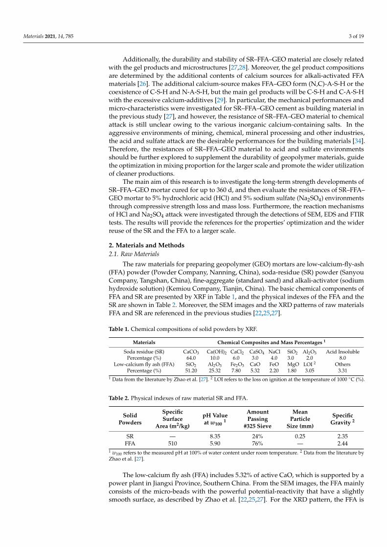
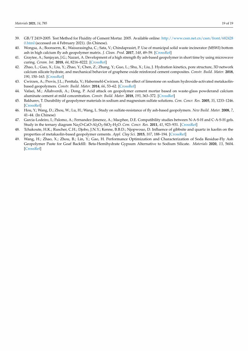
The long-term mechanical properties of SR–FFA–GEO mortars were further inves-tigated after clarifying the long-term physical properties. The compressive strengths ofSR–FFA–GEO mortars were recorded as curing time of up to 360 d, as shown in Figure 2.In the previous study, Bakharev [19] found that long-term pre-curing at room temperaturewas beneficial for the compressive strength development of FFA–GEO materials activatedby NaOH or Na2SiO3 solutions. It was revealed that the compressive strength of FFA–GEOwas significantly higher if FFA–GEOs were stored for 24 h, at room temperature, beforeapplication of heat curing (75 or 95 ◦C), compared to that stored for 2 h [19]. Moreover,the room-temperature curing was recommended for preparing FFA–GEO mortar in theprevious reference by Zhao et al. [27]. Therefore, the compressive strengths of M1 and M10cured at room temperature were measured at 90, 180, 270 and 360 d, respectively.
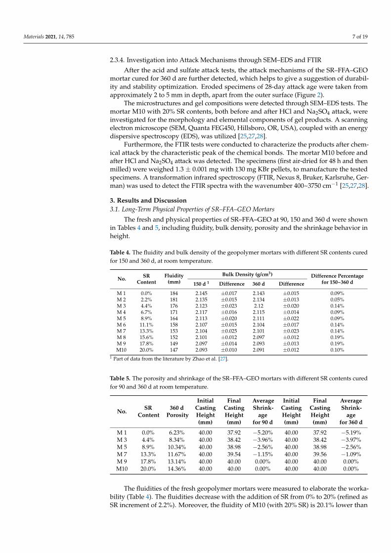
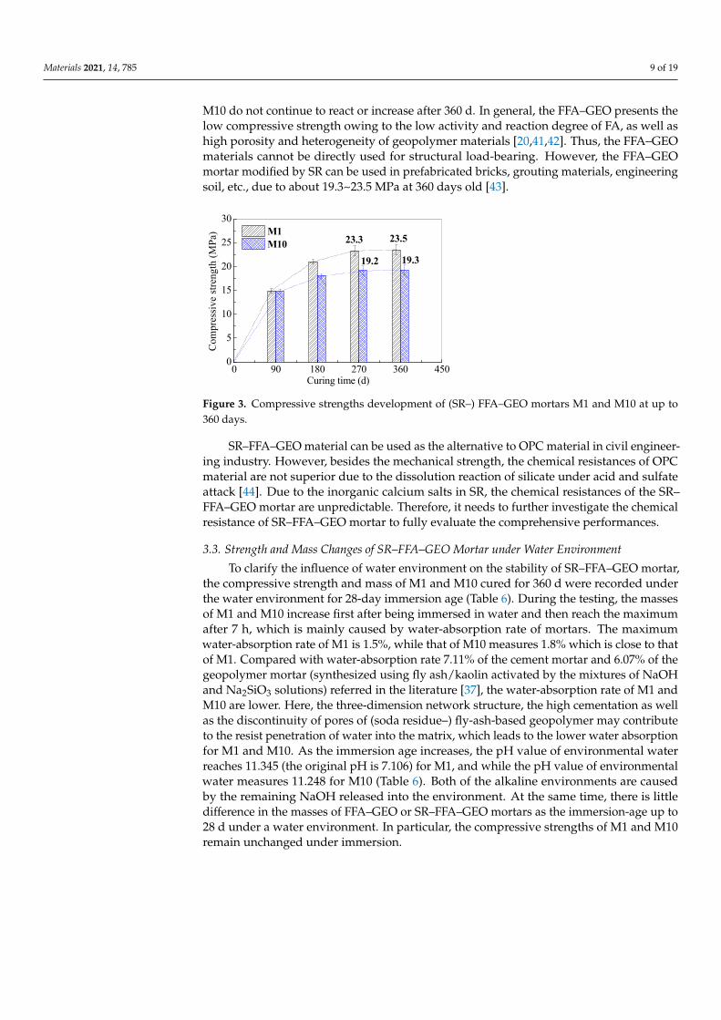
From Figure 3, it is can be seen that both of M1 and M10 show the increasing trendsin compressive strengths with the curing age. However, when it exceeds 270 d, thecompressive strength remains unchanged, indicating that the compressive strengths ofM1 and M10 are almost stable at 23.5 and 19.3 MPa at 360 days of age, respectively. ForM1, the compressive strength at 360 d is 11.9% higher than that (21 MPa) at 180 d, whilethe compressive strength at 360 d is 7.2% higher than that (18 MPa) at 180 d for M10.It is known that the generated gel products of N-A-S-H or (N,C)-A-S-H determine thelater strength development of alkali-activated FFA–GEO materials [25,27]. Therefore, itdemonstrates that the gel products in stable alkali-activated geopolymer mortars M1 and
Materials 2021, 14, 785 9 of 19
M10 do not continue to react or increase after 360 d. In general, the FFA–GEO presents thelow compressive strength owing to the low activity and reaction degree of FA, as well ashigh porosity and heterogeneity of geopolymer materials [20,41,42]. Thus, the FFA–GEOmaterials cannot be directly used for structural load-bearing. However, the FFA–GEOmortar modified by SR can be used in prefabricated bricks, grouting materials, engineeringsoil, etc., due to about 19.3~23.5 MPa at 360 days old [43].
Materials 2021, 14, x FOR PEER REVIEW 9 of 19
From Figure 3, it is can be seen that both of M1 and M10 show the increasing trends in compressive strengths with the curing age. However, when it exceeds 270 d, the com-pressive strength remains unchanged, indicating that the compressive strengths of M1 and M10 are almost stable at 23.5 and 19.3 MPa at 360 days of age, respectively. For M1, the compressive strength at 360 d is 11.9% higher than that (21 MPa) at 180 d, while the compressive strength at 360 d is 7.2% higher than that (18 MPa) at 180 d for M10. It is known that the generated gel products of N-A-S-H or (N,C)-A-S-H determine the later strength development of alkali-activated FFA–GEO materials [25,27]. Therefore, it demon-strates that the gel products in stable alkali-activated geopolymer mortars M1 and M10 do not continue to react or increase after 360 d. In general, the FFA–GEO presents the low compressive strength owing to the low activity and reaction degree of FA, as well as high porosity and heterogeneity of geopolymer materials [20,41,42]. Thus, the FFA–GEO ma-terials cannot be directly used for structural load-bearing. However, the FFA–GEO mortar modified by SR can be used in prefabricated bricks, grouting materials, engineering soil, etc., due to about 19.3~23.5 MPa at 360 days old [43].
SR–FFA–GEO material can be used as the alternative to OPC material in civil engi-neering industry. However, besides the mechanical strength, the chemical resistances of OPC material are not superior due to the dissolution reaction of silicate under acid and sulfate attack [44]. Due to the inorganic calcium salts in SR, the chemical resistances of the SR–FFA–GEO mortar are unpredictable. Therefore, it needs to further investigate the chemical resistance of SR–FFA–GEO mortar to fully evaluate the comprehensive perfor-mances.
Figure 3. Compressive strengths development of (SR–) FFA–GEO mortars M1 and M10 at up to 360 days.
3.3. Strength and Mass Changes of SR–FFA–GEO Mortar under Water Environment To clarify the influence of water environment on the stability of SR–FFA–GEO mor-
tar, the compressive strength and mass of M1 and M10 cured for 360 d were recorded under the water environment for 28-day immersion age (Table 6). During the testing, the masses of M1 and M10 increase first after being immersed in water and then reach the maximum after 7 h, which is mainly caused by water-absorption rate of mortars. The max-imum water-absorption rate of M1 is 1.5%, while that of M10 measures 1.8% which is close to that of M1. Compared with water-absorption rate 7.11% of the cement mortar and 6.07% of the geopolymer mortar (synthesized using fly ash/kaolin activated by the mixtures of NaOH and Na2SiO3 solutions) referred in the literature [37], the water-absorption rate of M1 and M10 are lower. Here, the three-dimension network structure, the high cementa-tion as well as the discontinuity of pores of (soda residue–) fly-ash-based geopolymer may contribute to the resist penetration of water into the matrix, which leads to the lower water absorption for M1 and M10. As the immersion age increases, the pH value of environmen-tal water reaches 11.345 (the original pH is 7.106) for M1, and while the pH value of envi-ronmental water measures 11.248 for M10 (Table 6). Both of the alkaline environments are
23.3 23.5
19.2 19.3
0 90 180 270 360 4500
5
10
15
20
25
30Co
mpr
essiv
e str
engt
h (M
Pa)
Curing time (d)
M1 M10
Figure 3. Compressive strengths development of (SR–) FFA–GEO mortars M1 and M10 at up to360 days.
SR–FFA–GEO material can be used as the alternative to OPC material in civil engineer-ing industry. However, besides the mechanical strength, the chemical resistances of OPCmaterial are not superior due to the dissolution reaction of silicate under acid and sulfateattack [44]. Due to the inorganic calcium salts in SR, the chemical resistances of the SR–FFA–GEO mortar are unpredictable. Therefore, it needs to further investigate the chemicalresistance of SR–FFA–GEO mortar to fully evaluate the comprehensive performances.
3.3. Strength and Mass Changes of SR–FFA–GEO Mortar under Water Environment
To clarify the influence of water environment on the stability of SR–FFA–GEO mortar,the compressive strength and mass of M1 and M10 cured for 360 d were recorded underthe water environment for 28-day immersion age (Table 6). During the testing, the massesof M1 and M10 increase first after being immersed in water and then reach the maximumafter 7 h, which is mainly caused by water-absorption rate of mortars. The maximumwater-absorption rate of M1 is 1.5%, while that of M10 measures 1.8% which is close to thatof M1. Compared with water-absorption rate 7.11% of the cement mortar and 6.07% of thegeopolymer mortar (synthesized using fly ash/kaolin activated by the mixtures of NaOHand Na2SiO3 solutions) referred in the literature [37], the water-absorption rate of M1 andM10 are lower. Here, the three-dimension network structure, the high cementation as wellas the discontinuity of pores of (soda residue–) fly-ash-based geopolymer may contributeto the resist penetration of water into the matrix, which leads to the lower water absorptionfor M1 and M10. As the immersion age increases, the pH value of environmental waterreaches 11.345 (the original pH is 7.106) for M1, and while the pH value of environmentalwater measures 11.248 for M10 (Table 6). Both of the alkaline environments are causedby the remaining NaOH released into the environment. At the same time, there is littledifference in the masses of FFA–GEO or SR–FFA–GEO mortars as the immersion-age up to28 d under a water environment. In particular, the compressive strengths of M1 and M10remain unchanged under immersion.
Materials 2021, 14, 785 10 of 19
Table 6. The compressive strengths and masses of M1 and M10 (cured for 360 d), under a waterenvironment, for a 28-day immersion age.
No. SRContent
Maximal WaterAbsorption at 7 h
EnvironmentalpH Value
ImmersionAge
CompressiveStrength (MPa)
MortarMass (g)
M 1 0.0% 1.5% 11.345
0 d 23.5 5437 d 23.6 541
14 d 23.6 54021 d 23.7 54028 d 23.7 540
M10 20.0% 1.8% 11.248
0 d 19.3 5407 d 19.3 542
14 d 19.4 54121 d 19.5 54128 d 19.5 541
Therefore, the mortars cured for 360 d have no significant changes in compressivestrength and mass losses under a water environment. Moreover, the M1 and M10 cured for360 d are recommended to further analyze the influence of HCl and Na2SO4 environmenton the performances of the SR–FFA–GEO mortars, with the exclusion of the continuationof internal hydration reaction.
3.4. Strength and Mass Losses of SR–FFA–GEO Mortar under HCl and Na2SO4 Attack
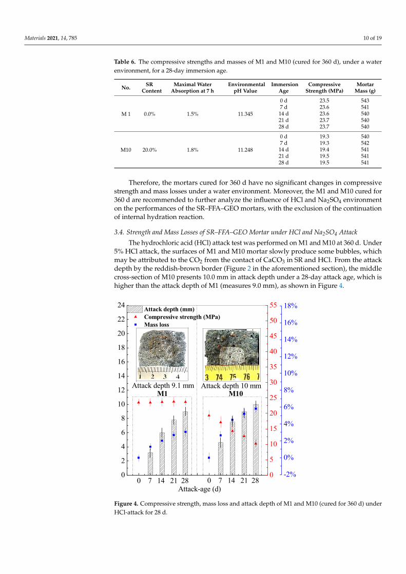
The hydrochloric acid (HCl) attack test was performed on M1 and M10 at 360 d. Under5% HCl attack, the surfaces of M1 and M10 mortar slowly produce some bubbles, whichmay be attributed to the CO2 from the contact of CaCO3 in SR and HCl. From the attackdepth by the reddish-brown border (Figure 2 in the aforementioned section), the middlecross-section of M10 presents 10.0 mm in attack depth under a 28-day attack age, which ishigher than the attack depth of M1 (measures 9.0 mm), as shown in Figure 4.
Materials 2021, 14, x FOR PEER REVIEW 11 of 19
Figure 4. Compressive strength, mass loss and attack depth of M1 and M10 (cured for 360 d) un-der HCl-attack for 28 d.
The sodium sulfate (Na2SO4) attack test was performed on M1 and M10 cured for 360 d at room temperature. Under 5% Na2SO4 solution, the compressive strength and mass loss were recorded for 28-day attack age (Figure 5). It can be seen that no mass losses occur for M1 and M10, while the compressive strengths of M1 and M10 remain stable with the attack age.
In the previous study, the FA activated by sodium silicate solution (modulus 1.2, and mass concentration 32%) was prepared geopolymer cured for 1 d at 25 °C and then for 2 d at 80 °C. The compressive strength of the prepared FA–GEO increases with the attack age under 5% Na2SO4 attack [46]. The compressive strength of the mentioned FA–GEO cannot reach the maximum at temperature-curing for 3 d. Under the Na2SO4 attack, the geopolymerization reaction still continues to occur, which may be because the environ-mental Na+ cations enter the network structure formed with Si-O-Al chains through dif-fusion and promote the positive effect on the polymerization degree of Si-O-Al bond [34,45]. Therefore, without compressive strength loss and mass loss occurring, it can be determined that the resistances of M1 and M10 cured for 360 d to Na2SO4 attack are supe-rior and evenly superior to that of OPC mortar (Table 7). That is because that the calcium silicate hydrated gels in OPC mortar are continuously dissolved by HCl, and the sands fall off from the mortar under 5% HCl attack, which leads to the higher losses in mass and compressive strength for OPC mortar.
0
2
4
6
8
10
12
14
16
18
20
22
24
0 7 14 21 28
Attack depth (mm) Compressive strength (MPa) Mass loss
Attack-age (d)0 7 14 21 28
Attack depth 10 mmAttack depth 9.1 mm
0
5
10
15
20
25
30
35
40
45
50
55
M10 M1
-2%
0%
2%
4%
6%
8%
10%
12%
14%
16%
18%
Figure 4. Compressive strength, mass loss and attack depth of M1 and M10 (cured for 360 d) underHCl-attack for 28 d.
Materials 2021, 14, 785 11 of 19
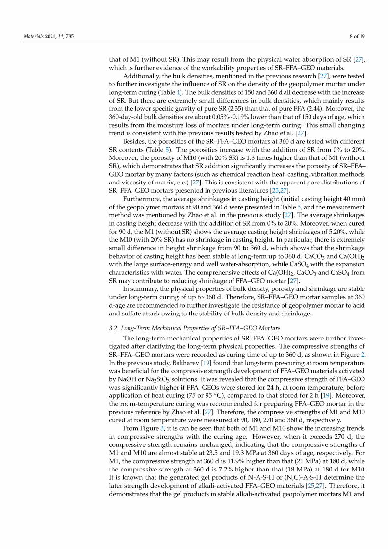
The compressive strength and mass loss under a 28-day attack age were recorded inFigure 4. The mass losses of M1 and M10 increase with the attack age. The mass loss of M10reaches 5.82% at a 2-day attack age, while the mass loss of M1 reaches 3.06%. However,the compressive strength of M1 keeps stable, and that of M10 decreases by 47.2% aftera 28-day attack age. The mortar M1 possesses the good resistance to HCl attack, owingto a three-dimensional stable network structure. Thus, M1 has little mass loss (3.06%)and unchanged compressive strength under HCl attack, which is consistent with that ofhigh-strength FA–GEO material mentioned in the previous study [34,45]. Moreover, themortar M10 possesses the worse resistance to HCl attack than that of M1, which mayresult from the calcites in SR. The formed M10 was porous due to a variety of factors, suchas pouring and vibration, viscosity, reaction heat, etc. [27]. Here, the calcites in porousSR reacted with HCl, to produce more porosity for M10, which led to the decrement ofcompressive strength. However, the resistance of M10 to HCl attack (mass loss 5.82% andstrength loss 47.2%) is higher than that of OPC mortar in the previous study (mass loss40.97% and strength loss 85.2%) [37] at a 28-day attack age (Table 7).
Table 7. The compressive strength and mass losses of M10 (cured for 360 d) and Ordinary PortlandCement (OPC) mortar under HCl-attack and Na2SO4-attack environment for 28 d.
SamplesSR
Content5% HCl-Attack 5% Na2SO4-Attack
Strength Loss Mass Loss Strength Loss Mass Loss
M10 20% 47.2% 5.82% 0.0% 0.00%OPC 1 — 85.2% 40.97% 5.8% 6.83%
1 Part of data from the literature [37].
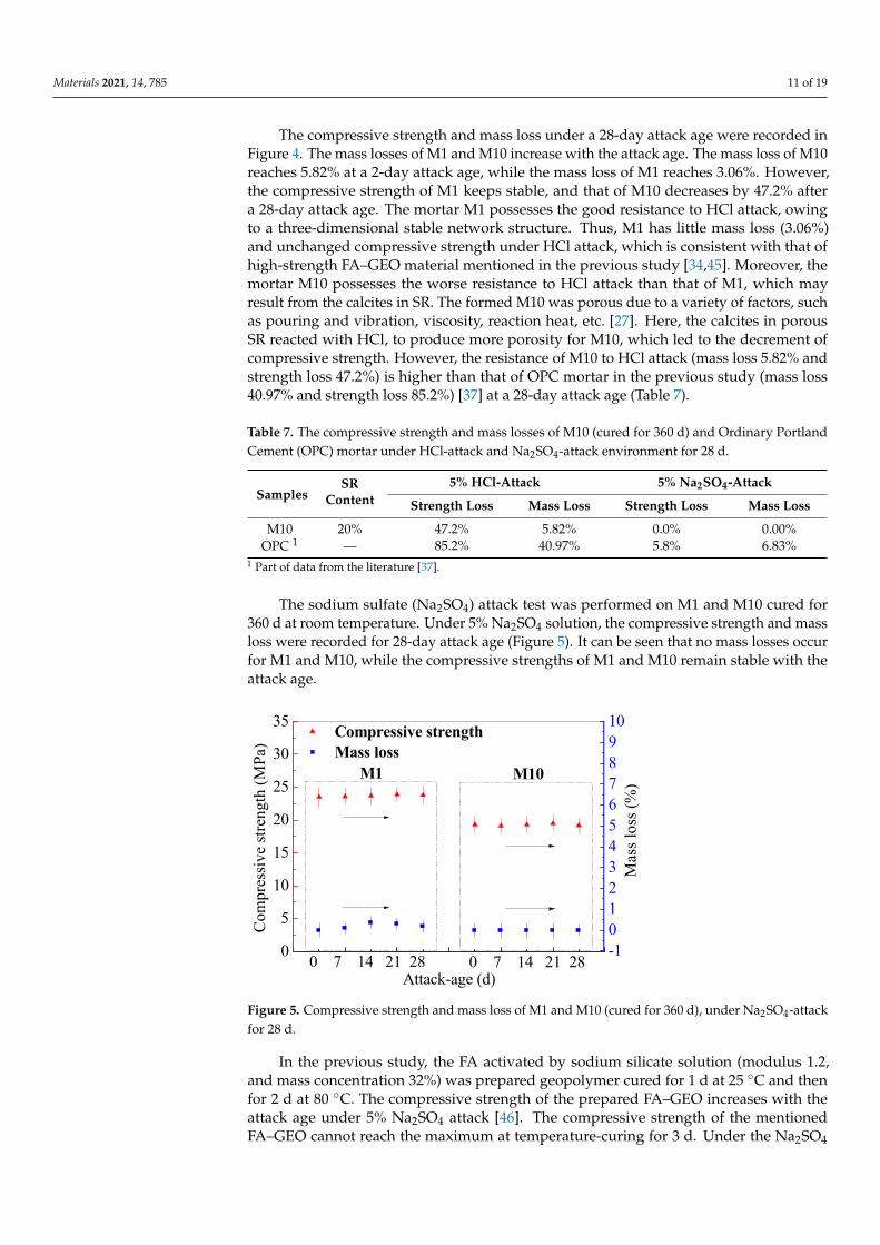
The sodium sulfate (Na2SO4) attack test was performed on M1 and M10 cured for360 d at room temperature. Under 5% Na2SO4 solution, the compressive strength and massloss were recorded for 28-day attack age (Figure 5). It can be seen that no mass losses occurfor M1 and M10, while the compressive strengths of M1 and M10 remain stable with theattack age.
Materials 2021, 14, x FOR PEER REVIEW 12 of 19
Figure 5. Compressive strength and mass loss of M1 and M10 (cured for 360 d), under Na2SO4-attack for 28 d.
Table 7. The compressive strength and mass losses of M10 (cured for 360 d) and Ordinary Port-land Cement (OPC) mortar under HCl-attack and Na2SO4-attack environment for 28 d.
Samples SR
Content 5% HCl-Attack 5% Na2SO4-Attack
Strength Loss Mass Loss Strength Loss Mass Loss M10 20% 47.2% 5.82% 0.0% 0.00%
OPC 1 — 85.2% 40.97% 5.8% 6.83% 1 Part of data from the literature [37].
3.5. Microstructures and Gel Products under HCl and Na2SO4 Attack through SEM–EDS Anal-ysis
Compressive strengths and mass losses are the macroscopic characterization of the chemical attack phenomenon, and it is necessary to further characterize the changes be-fore and after chemical attack from the microstructure and gel product. It helps to reveal the attack mechanism of HCl and Na2SO4 solution.
After clarifying the compressive strength and mass loss of SR–FFA–GEO mortars un-der HCl and Na2SO4 environment, the attack mechanism of SR–FFA–GEO mortar was further revealed through the analysis of microstructures and elemental composites before and after attack. The ten different locations were probed when determining the Ca/Si and Si/Al ratios from the EDS. The SEM images are the representative images in the revised manuscript (Figures 6 and 7). The testing method of SEM–EDS is to first probe the entire window to select the specific gel product not standard stand according to the elemental components (Si, Al, Na, O, Ca, etc.) [26]. Then, the selected representative micro-areas were used to probe the specific locations to get effective information of gel products before and after chemical attack. The testing results are obtained from the elemental components at the representative micro-areas. The abovementioned method greatly removes the influ-ence of standard sand (quartz), and that pays more attention to the change of gel products.
The morphologies of M10 were observed by SEM images before and after attack (Fig-ure 6). There still are some undissolved glassy microspheres of FA in mortar M10 before HCl and Na2SO4 attack. After HCl attack for 28 d, the glassy microspheres are further dissolved, whereas the glassy microspheres have no change after Na2SO4 attack for 28 d. After magnification, it is found that the formed gel products are observed on the surface of M10 (Figure 7a–c).
From the representative EDS spectra and elemental components from area-scanning technology (Figure 7), calcium elements (Ca) in gel products of M10 decrease after HCl attack, while there are no sulfate elements (S) in gel products after Na2SO4 attack. Under Na2SO4 attack, SO42− ions in environment cannot enter the geopolymer mortar through
0
5
10
15
20
25
30
35
M10
Compressive strength Mass loss
Attack-age (d)
Com
pres
sive
stren
gth
(MPa
)
M1
-1012345678910
0 7 14 21 280 7 14 21 28
Mas
s los
s (%
)
Figure 5. Compressive strength and mass loss of M1 and M10 (cured for 360 d), under Na2SO4-attackfor 28 d.
In the previous study, the FA activated by sodium silicate solution (modulus 1.2,and mass concentration 32%) was prepared geopolymer cured for 1 d at 25 ◦C and thenfor 2 d at 80 ◦C. The compressive strength of the prepared FA–GEO increases with theattack age under 5% Na2SO4 attack [46]. The compressive strength of the mentionedFA–GEO cannot reach the maximum at temperature-curing for 3 d. Under the Na2SO4
Materials 2021, 14, 785 12 of 19
attack, the geopolymerization reaction still continues to occur, which may be becausethe environmental Na+ cations enter the network structure formed with Si-O-Al chainsthrough diffusion and promote the positive effect on the polymerization degree of Si-O-Albond [34,45]. Therefore, without compressive strength loss and mass loss occurring, it canbe determined that the resistances of M1 and M10 cured for 360 d to Na2SO4 attack aresuperior and evenly superior to that of OPC mortar (Table 7). That is because that thecalcium silicate hydrated gels in OPC mortar are continuously dissolved by HCl, and thesands fall off from the mortar under 5% HCl attack, which leads to the higher losses inmass and compressive strength for OPC mortar.
3.5. Microstructures and Gel Products under HCl and Na2SO4 Attack through SEM–EDSAnalysis
Compressive strengths and mass losses are the macroscopic characterization of thechemical attack phenomenon, and it is necessary to further characterize the changes beforeand after chemical attack from the microstructure and gel product. It helps to reveal theattack mechanism of HCl and Na2SO4 solution.
After clarifying the compressive strength and mass loss of SR–FFA–GEO mortarsunder HCl and Na2SO4 environment, the attack mechanism of SR–FFA–GEO mortar wasfurther revealed through the analysis of microstructures and elemental composites beforeand after attack. The ten different locations were probed when determining the Ca/Si andSi/Al ratios from the EDS. The SEM images are the representative images in the revisedmanuscript (Figures 6 and 7). The testing method of SEM–EDS is to first probe the entirewindow to select the specific gel product not standard stand according to the elementalcomponents (Si, Al, Na, O, Ca, etc.) [26]. Then, the selected representative micro-areas wereused to probe the specific locations to get effective information of gel products before andafter chemical attack. The testing results are obtained from the elemental components atthe representative micro-areas. The abovementioned method greatly removes the influenceof standard sand (quartz), and that pays more attention to the change of gel products.
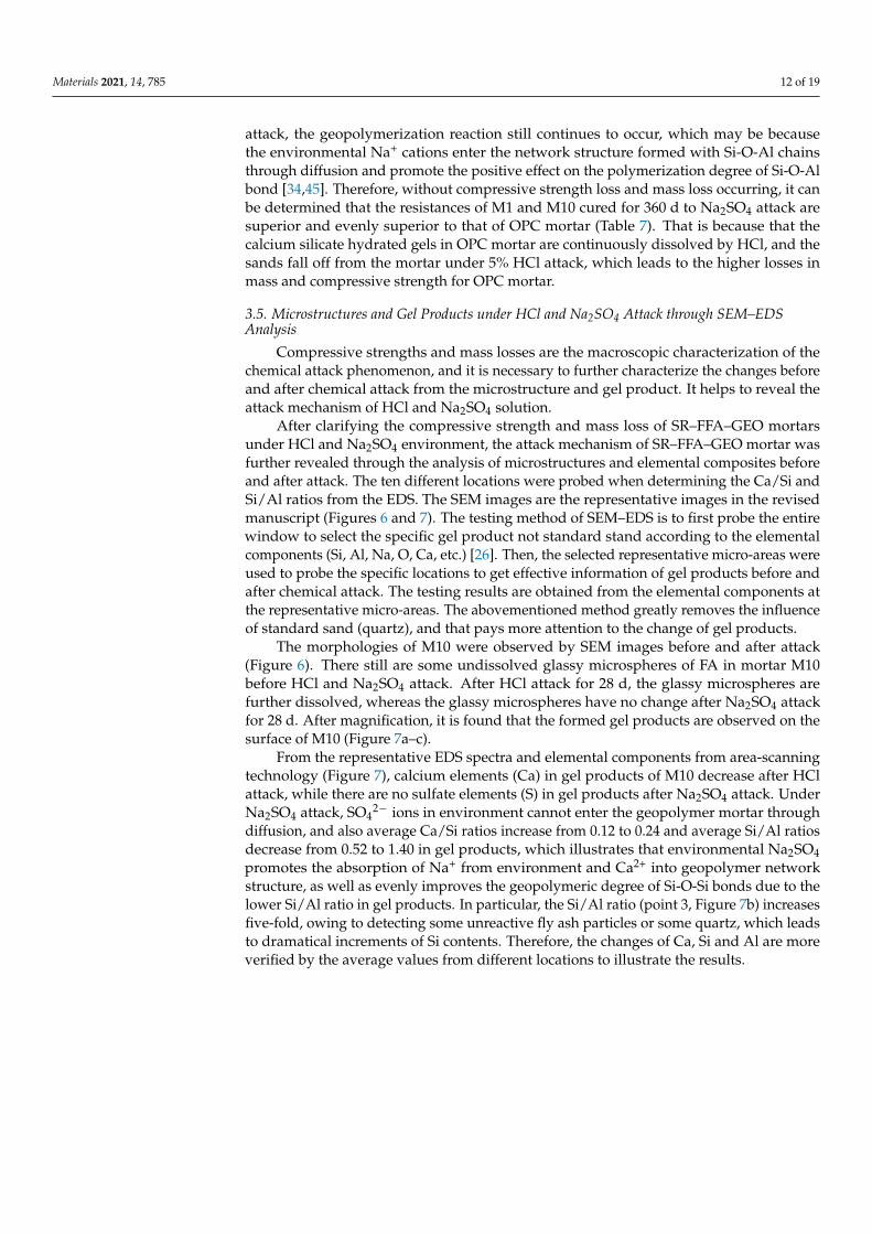
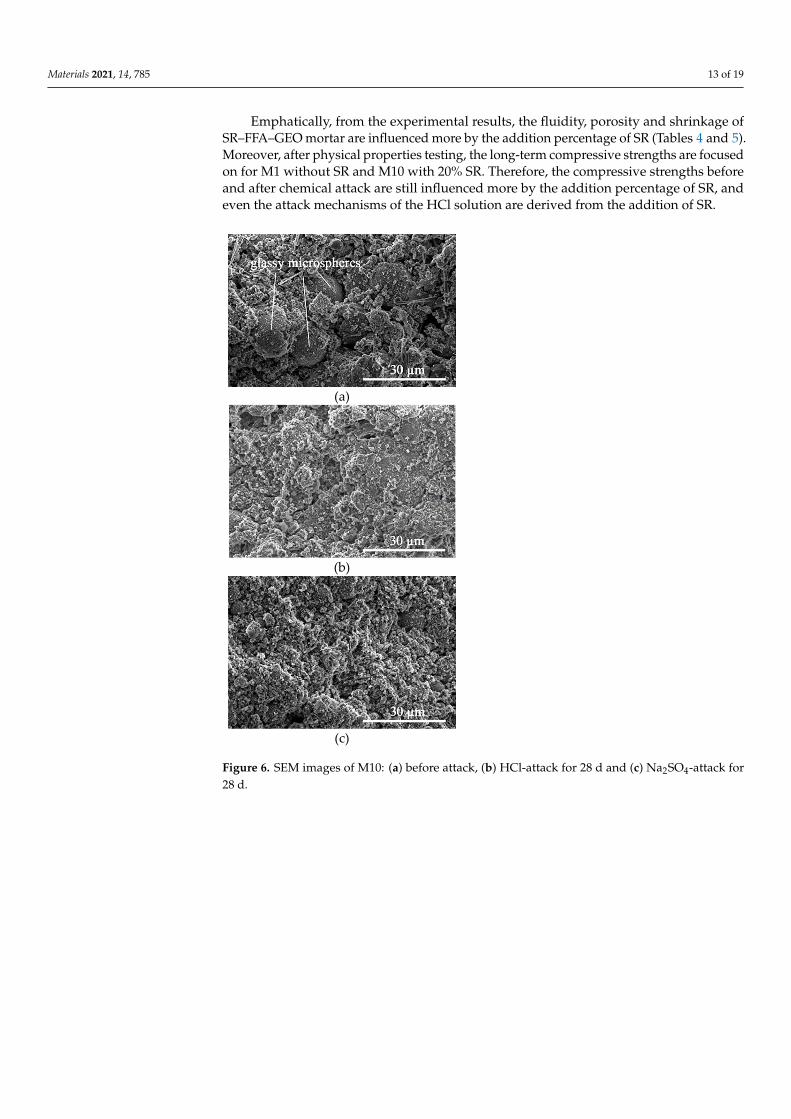
The morphologies of M10 were observed by SEM images before and after attack(Figure 6). There still are some undissolved glassy microspheres of FA in mortar M10before HCl and Na2SO4 attack. After HCl attack for 28 d, the glassy microspheres arefurther dissolved, whereas the glassy microspheres have no change after Na2SO4 attackfor 28 d. After magnification, it is found that the formed gel products are observed on thesurface of M10 (Figure 7a–c).
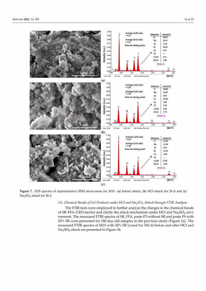
From the representative EDS spectra and elemental components from area-scanningtechnology (Figure 7), calcium elements (Ca) in gel products of M10 decrease after HClattack, while there are no sulfate elements (S) in gel products after Na2SO4 attack. UnderNa2SO4 attack, SO4
2− ions in environment cannot enter the geopolymer mortar throughdiffusion, and also average Ca/Si ratios increase from 0.12 to 0.24 and average Si/Al ratiosdecrease from 0.52 to 1.40 in gel products, which illustrates that environmental Na2SO4promotes the absorption of Na+ from environment and Ca2+ into geopolymer networkstructure, as well as evenly improves the geopolymeric degree of Si-O-Si bonds due to thelower Si/Al ratio in gel products. In particular, the Si/Al ratio (point 3, Figure 7b) increasesfive-fold, owing to detecting some unreactive fly ash particles or some quartz, which leadsto dramatical increments of Si contents. Therefore, the changes of Ca, Si and Al are moreverified by the average values from different locations to illustrate the results.
Materials 2021, 14, 785 13 of 19
Emphatically, from the experimental results, the fluidity, porosity and shrinkage ofSR–FFA–GEO mortar are influenced more by the addition percentage of SR (Tables 4 and 5).Moreover, after physical properties testing, the long-term compressive strengths are focusedon for M1 without SR and M10 with 20% SR. Therefore, the compressive strengths beforeand after chemical attack are still influenced more by the addition percentage of SR, andeven the attack mechanisms of the HCl solution are derived from the addition of SR.
Materials 2021, 14, x FOR PEER REVIEW 13 of 19
diffusion, and also average Ca/Si ratios increase from 0.12 to 0.24 and average Si/Al ratios decrease from 0.52 to 1.40 in gel products, which illustrates that environmental Na2SO4 promotes the absorption of Na+ from environment and Ca2+ into geopolymer network structure, as well as evenly improves the geopolymeric degree of Si-O-Si bonds due to the lower Si/Al ratio in gel products. In particular, the Si/Al ratio (point 3, Figure 7b) increases five-fold, owing to detecting some unreactive fly ash particles or some quartz, which leads to dramatical increments of Si contents. Therefore, the changes of Ca, Si and Al are more verified by the average values from different locations to illustrate the results.
Emphatically, from the experimental results, the fluidity, porosity and shrinkage of SR–FFA–GEO mortar are influenced more by the addition percentage of SR (Tables 4 and 5). Moreover, after physical properties testing, the long-term compressive strengths are focused on for M1 without SR and M10 with 20% SR. Therefore, the compressive strengths before and after chemical attack are still influenced more by the addition percentage of SR, and even the attack mechanisms of the HCl solution are derived from the addition of SR.
(a)
(b)
(c)
Figure 6. SEM images of M10: (a) before attack, (b) HCl-attack for 28 d and (c) Na2SO4-attack for 28 d. Figure 6. SEM images of M10: (a) before attack, (b) HCl-attack for 28 d and (c) Na2SO4-attack for28 d.
Materials 2021, 14, 785 14 of 19Materials 2021, 14, x FOR PEER REVIEW 14 of 19
(a)
(b)
(c)
Figure 7. EDS spectra of representative SEM micro-areas for M10: (a) before attack, (b) HCl-attack for 28 d and (c) Na2SO4-attack for 28 d.
3.6. Chemical Bonds of Gel Products under HCl and Na2SO4 Attack through FTIR Analysis The FTIR tests were employed to further analyze the changes in the chemical bonds
of SR–FFA–GEO mortar and clarify the attack mechanism under HCl and Na2SO4 envi-ronment. The measured FTIR spectra of SR, FFA, paste P3 without SR and paste P9 with 20% SR were presented for 180-day-old samples in the previous study (Figure 8a). The measured FTIR spectra of M10 with 20% SR (cured for 360 d) before and after HCl and Na2SO4 attack are presented in Figure 8b.
All wavenumbers at 777, 797 and 779 cm−1 correspond to the bending vibration ab-sorptions of Si-O and Al-O bonds. The main absorption peaks attributed to Si-O-T (Si or Al) with the asymmetrical stretching vibrations are at the region from 1000 to 1100 cm−1 [15,47,48]. The absorptions at 1458 cm−1 mainly are attributed to the asymmetric stretching vibration of CO32− bond in carbonate, and then the absorption peaks at 1637 and 3448 cm−1, respectively, correspond to the bending vibration of H-O-H bond and the stretching vi-bration of -OH bonds in weakly bound water [19,45].
Figure 7. EDS spectra of representative SEM micro-areas for M10: (a) before attack, (b) HCl-attack for 28 d and (c)Na2SO4-attack for 28 d.
3.6. Chemical Bonds of Gel Products under HCl and Na2SO4 Attack through FTIR Analysis
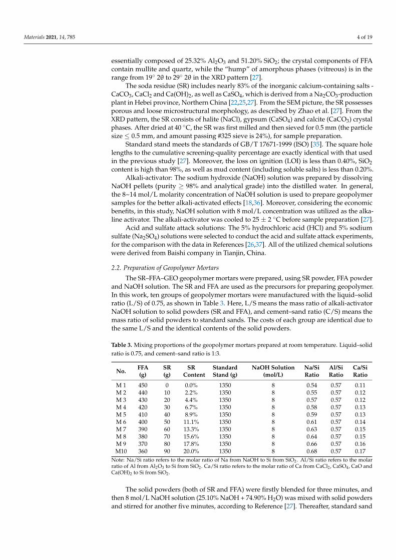
The FTIR tests were employed to further analyze the changes in the chemical bondsof SR–FFA–GEO mortar and clarify the attack mechanism under HCl and Na2SO4 envi-ronment. The measured FTIR spectra of SR, FFA, paste P3 without SR and paste P9 with20% SR were presented for 180-day-old samples in the previous study (Figure 8a). Themeasured FTIR spectra of M10 with 20% SR (cured for 360 d) before and after HCl andNa2SO4 attack are presented in Figure 8b.
Materials 2021, 14, 785 15 of 19Materials 2021, 14, x FOR PEER REVIEW 16 of 19
(a)
(b)
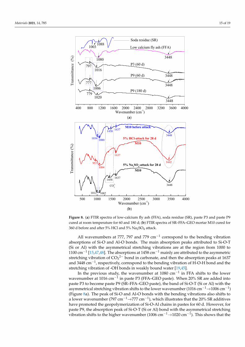
Figure 8. (a) FTIR spectra of low-calcium fly ash (FFA), soda residue (SR), paste P3 and paste P9 cured at room temperature for 60 and 180 d; (b) FTIR spectra of SR–FFA–GEO mortar M10 cured for 360 d before and after 5% HCl and 5% Na2SO4 attack.
4. Conclusions The aim of this paper is to validate the resistance of soda residue/low-calcium-fly-
ash-based geopolymer mortar to acid and sulfate environments and explore the chemical attack mechanism of the geopolymer mortar. Conclusions could be obtained as follows: (1) The compressive strengths (19.3 MPa) of soda residue/low-calcium-fly-ash-based ge-
opolymer mortar with 20% soda residue are stable at 360 days old, when cured at room temperature. In particular, the compressive strength, porosity and shrinkage are influenced more by the addition percentage of soda residue. Moreover, the geo-polymer mortar with 20% soda residue (with low water absorption of 1.8%) keeps stable in compressive strength and mass loss under water environment for 360 d.
(2) The soda residue/low-calcium-fly-ash-based geopolymer mortar with 20% soda res-idue cured for 360 d at room temperature is recommended to investigate the re-sistance to acid and sulfate attack owing to the better stability with the exclusion of internal hydration.
400 800 1200 1600 2000 2400 2800 3200 3600 4000
3448
3448
3448
3448
1020779
1006
1016
777
7971080
10031088
Tran
smitt
ance
(%
)
P9 (180 d)
P9 (60 d)
P3 (60 d)
Low calcium fly ash (FFA)
Wavenumber (cm-1)
Soda residue (SR)
500 1000 1500 2000 2500 3000 3500 4000
M10
M10
5% Na2SO4-attack for 28 d
M10 before attack
5% HCl-attack for 28 d
Tran
smitt
ance
(%)
Wavenumber (cm-1)
1012 1082
1080
1084955
1458
1458
1637
1637
3448
1637
3442
3448
CO2-3
1034
Figure 8. (a) FTIR spectra of low-calcium fly ash (FFA), soda residue (SR), paste P3 and paste P9cured at room temperature for 60 and 180 d; (b) FTIR spectra of SR–FFA–GEO mortar M10 cured for360 d before and after 5% HCl and 5% Na2SO4 attack.
All wavenumbers at 777, 797 and 779 cm−1 correspond to the bending vibrationabsorptions of Si-O and Al-O bonds. The main absorption peaks attributed to Si-O-T(Si or Al) with the asymmetrical stretching vibrations are at the region from 1000 to1100 cm−1 [15,47,48]. The absorptions at 1458 cm−1 mainly are attributed to the asymmetricstretching vibration of CO3
2− bond in carbonate, and then the absorption peaks at 1637and 3448 cm−1, respectively, correspond to the bending vibration of H-O-H bond and thestretching vibration of -OH bonds in weakly bound water [19,45].
In the previous study, the wavenumber at 1080 cm−1 in FFA shifts to the lowerwavenumber at 1016 cm−1 in paste P3 (FFA–GEO paste). When 20% SR are added intopaste P3 to become paste P9 (SR–FFA–GEO paste), the band of Si-O-T (Si or Al) with theasymmetrical stretching vibration shifts to the lower wavenumber (1016 cm−1→1006 cm−1)(Figure 8a). The peak of Si-O and Al-O bonds with the bending vibrations also shifts toa lower wavenumber (797 cm−1→777 cm−1), which illustrates that the 20% SR additiveshave promoted the geopolymerization of Si-O-Al chains in pastes for 60 d. However, forpaste P9, the absorption peak of Si-O-T (Si or Al) bond with the asymmetrical stretchingvibration shifts to the higher wavenumber (1006 cm−1→1020 cm−1). This shows that the
Materials 2021, 14, 785 16 of 19
polymerization of Si-O-Si bond distinctly occurs and further promotes the formation ofC-S-H gels by the 20% SR additives during 60~180 d. Additionally, the alkaline SRs consistof the high contents of Ca(OH)2, CaCO3, CaCl2 and CaSO4. The Ca2+ cations dissolvedfrom the additional SRs participate in the form of C-S-H and C-A-S-H gels by providingthe nucleation location for (N,C)-A-S-H or/and N-A-S-H [29]. Therefore, the gel productsof (N,C)-A-S-H, C-S-H and C-A-S-H are verified in SR–FFA–GEO (paste and mortar) with20% SR.
The SR was used with blend of FFA and alkali-activator solution to prepare thegeopolymer grouting paste for goaf backfill [25]. The prepared paste occurs the chemicalreaction of geopolymerization between Si-O and Al-O bonds to generate the mixtures of(Ca, Na)-containing aluminosilicate polymer gel (N,C)-A-S-H and calcium silicate hydratedgel C-S-H. Additionally, the SR also was used with FFA, beta-hemihydrate gypsum andalkali-activator solution, to manufacture the geopolymer slurry for goaf backfill [49]. Thereaction mechanism of geopolymerization and hydration process still happen to form thecoexistence of (N,C)-A-S-H and C-S-H gels, along with the hydration of gypsum. Theseabove-verified gel products support the chemical reaction mechanism and hardeningmechanism of SR–FFA–GEO mortar M10 for the FTIR results.
Under 5% HCl attack, for the M10 with 20% SR, the weak absorption peak at 1034 cm−1
shifts to a lower wavenumber at 955 cm−1 (Figure 8b), indicating that HCl dissolves theglassy microspheres of FFA to generate the silicon and aluminum monomers. Moreover, theabsorption peak attributed to CO3
2− bond disappeared at 1458 cm−1. The peak intensitiesat 1637 and 3448 cm−1 increase, and also the absorption peak at 3448 cm−1 shifts to thelower wavenumber 3442 cm−1, which indicates that the carbonates (namely calcite) from SRdecompose under HCl attack, and a part of water is adsorbed on the surface of geopolymer.In the previous study, Zhao et al. [26] found through FTIR and XRD that calcites werewrapped with N-A-S-H and (N,C)-A-S-H gels in SR–FFA–GEO paste, and calcites didnot occur chemical reaction. But here, with HCl solution attack, the environmental HClsolution goes gently inside the formed gels and reacts with the calcites to increase theporosity and decrease the compressive strength.
Under 5% Na2SO4 attack, the absorption peak at 1034 cm−1 (before attack) shiftsto the lower wavenumber 1012 cm−1 (Figure 8b), which shows that Na2SO4 promotesthe geopolymerization of Si-O-Al bonds, and more additional Al (dissolved from fly ashparticles) promote the absorption of Na+ and Ca2+ cations in network structure. The highergeopolymeric degrees of Si-O-Al bonds determine the lower Si/Al molar ratio in the gelproduct. The aluminosilicate gel is formed by Si-O-Al or Si-O-Si bonds, owing to thecharge balance between Al and metal cations, and the positive charge is compensated bymetal cation (Na+, K+ and Ca2+). Therefore, the higher Si/Al ratios, which are reflectedin Figure 8b, determine the more dissolution of Al and resist penetration of SO4
2− ions.These conclusions can be clarified by SEM–EDS tests. Moreover, the more environmentalNa+ cations entering the Si-O-Al network structure were also verified by the SEM–EDStests under Na2SO4 attack.
4. Conclusions
The aim of this paper is to validate the resistance of soda residue/low-calcium-fly-ash-based geopolymer mortar to acid and sulfate environments and explore the chemicalattack mechanism of the geopolymer mortar. Conclusions could be obtained as follows:
(1) The compressive strengths (19.3 MPa) of soda residue/low-calcium-fly-ash-basedgeopolymer mortar with 20% soda residue are stable at 360 days old, when cured atroom temperature. In particular, the compressive strength, porosity and shrinkageare influenced more by the addition percentage of soda residue. Moreover, thegeopolymer mortar with 20% soda residue (with low water absorption of 1.8%) keepsstable in compressive strength and mass loss under water environment for 360 d.
(2) The soda residue/low-calcium-fly-ash-based geopolymer mortar with 20% sodaresidue cured for 360 d at room temperature is recommended to investigate the
Materials 2021, 14, 785 17 of 19
resistance to acid and sulfate attack owing to the better stability with the exclusion ofinternal hydration.
(3) Under 5% HCl solution attack for 28 d, the mass loss of the geopolymer mortar with20% soda residue reaches 5.82%, and the compressive strength loss is 47.2%. However,under 5% Na2SO4 solution attack for 28 d, there is no compressive strength and masslosses for the geopolymer mortar with 20% soda residue. Therefore, the geopolymermortar with 20% soda residue possesses the superior resistance to Na2SO4 attack,as well as the better resistance to HCl attack than that of ordinary Portland cementmaterial.
(4) From the SEM–EDS and FTIR analysis, the calcites from soda residue cause thechemical reaction with the environmental HCl to produce some CO2 gas, which leadsto the losses in compressive strength and mass under HCl attack. Thus, the attackmechanisms of HCl solution are derived from the addition of soda residue. Moreover,more Na+ cations entering the Si-O-Al structure make soda residue/low-calcium-fly-ash-based geopolymer mortar obtain the superior resistance to Na2SO4 attackwithout compressive strength loss and mass loss.
In summary, the resistances of the soda residue/low-calcium-fly-ash-based geopoly-mer mortar (4:1 mass ratio of low calcium fly ash and soda residue, 1:3 of cement–sand, 8mol/L NaOH solution and 0.75 liquid–solid ratio) to 5% HCl and 5% Na2SO4 environmentsare superior to that of ordinary Portland cement mortar. The contribution of this work is tovalidate the resistance performance to acid and sulfate environments and reveal the attackmechanism of the prepared geopolymer mortar incorporating soda residue. It supportsthe durable evaluation of soda residue/low-calcium-fly-ash-based geopolymer mortar.However, the soda residue/low-calcium-fly-ash-based geopolymer mortar presents thehigh porosity of 14.36% in the physical properties. In the next works, the porosity-reductionmethod of low-calcium-fly-ash-based geopolymer mortar incorporating soda residue willbe further explored, to achieve high strength or evaluate the freezing stability.
Author Contributions: Conceptualization, X.Z. and H.W.; formal analysis, H.G.; funding acquisition,H.W.; investigation, X.Z., H.W. and B.Z.; methodology, Y.L.; project administration, Y.L.; resources,H.G. and Y.L.; supervision, X.Z. and H.W.; validation, X.Z. and B.Z.; writing—original draft, X.Z. andB.Z.; writing—review and editing, H.W. All authors have read and agreed to the published versionof the manuscript.
Funding: This research was funded by the Science and Technology Project Foundation of HebeiProvince, China, grant numbers 15273802D and 16273809.
Data Availability Statement: The data presented in this study are available on request from thecorresponding author. The data are not publicly available due to the privacy restrictions.
Conflicts of Interest: The authors declare no conflict of interest.
References1. Tho-In, T.; Sata, V.; Boonserm, K.; Chindaprasirt, P. Compressive strength and microstructure analysis of geopolymer paste using
waste glass powder and fly ash. J. Clean. Prod. 2018, 172, 2892–2898. [CrossRef]2. Zhuang, X.Y.; Chen, L.; Komarneni, S.; Zhou, C.H.; Tong, D.S.; Yang, H.M.; Yu, W.H.; Wang, H. Fly ash-based geopolymer: Clean
production, properties and applications. J. Clean. Prod. 2016, 125, 253–267. [CrossRef]3. Hu, W.; Nie, Q.; Huang, B.; Shu, X.; He, Q. Mechanical and microstructural characterization of geopolymers derived from red
mud and fly ashes. J. Clean. Prod. 2018, 186, 799–806. [CrossRef]4. Assi, L.; Carter, K.; Deaver, E.; Anay, R.; Ziehl, P. Sustainable concrete: Building a greener future. J. Clean. Prod. 2018, 198,
1641–1651. [CrossRef]5. Nematollahi, B.; Sanjayan, J.; Shaikh, F.U.A. Synthesis of heat and ambient cured one-part geopolymer mixes with different
grades of sodium silicate. Ceram. Int. 2015, 41, 5696–5704. [CrossRef]6. Roviello, G.; Ricciotti, L.; Tarallo, O.; Ferone, C.; Colangelo, F.; Roviello, V.; Cioffi, R. Innovative Fly Ash Geopolymer-Epoxy
Composites: Preparation, Microstructure and Mechanical Properties. Materials 2016, 9, 461. [CrossRef] [PubMed]7. Castel, A.; Foster, S.J. Bond strength between blended slag and Class F fly ash geopolymer concrete with steel reinforcement. Cem.
Concr. Res. 2015, 72, 48–53. [CrossRef]
Materials 2021, 14, 785 18 of 19
8. Sarker, P.K.; McBeath, S. Fire endurance of steel reinforced fly ash geopolymer concrete elements. Constr. Build. Mater. 2015, 90,91–98. [CrossRef]
9. Hashimoto, S.; Machino, T.; Ando, K.; Daiko, Y.; Honda, S.; Iwamoto, Y. Hot sulfuric acid-resistance of fly-ash-based geopolymerpaste product due to the precipitation of natroalunite crystals. Constr. Build. Mater. 2017, 151, 714–719. [CrossRef]
10. Colangelo, F.; Cioffi, R.; Roviello, G.; Capasso, I.; Caputo, D.; Aprea, P.; Liguori, B.; Ferone, C. Thermal cycling stability of fly ashbased geopolymer mortars. Compos. Part. B-Eng. 2017, 129, 11–17. [CrossRef]
11. Pasupathy, K.; Berndt, M.; Sanjayan, J.; Rajeev, P.; Cheema, D.S. Durability of low-calcium fly ash based geopolymer concreteculvert in a saline environment. Cem. Concr. Res. 2017, 100, 297–310. [CrossRef]
12. Saha, S.; Rajasekaran, C. Enhancement of the properties of fly ash based geopolymer paste by incorporating ground granulatedblast furnace slag. Constr. Build. Mater. 2017, 146, 615–620. [CrossRef]
13. Gorhan, G.; Kurklu, G. The influence of the NaOH solution on the properties of the fly ash-based geopolymer mortar cured atdifferent temperatures. Compos. Part. B Eng. 2014, 58, 371–377. [CrossRef]
14. Xu, F.; Deng, X.; Peng, C.; Zhu, J.; Chen, J. Mix design and flexural toughness of PVA fiber reinforced fly ash-geopolymercomposites. Constr. Build. Mater. 2017, 150, 179–189. [CrossRef]
15. Swanepoel, J.C.; Strydom, C.A. Utilisation of fly ash in a geopolymeric material. Appl. Geochem. 2002, 17, 1143–1148. [CrossRef]16. Pavithra, P.; Reddy, M.S.; Dinakar, P.; Rao, B.H.; Satpathy, B.K.; Mohanty, A.N. A mix design procedure for geopolymer concrete
with fly ash. J. Clean. Prod. 2016, 133, 117–125. [CrossRef]17. Somna, K.; Jaturapitakkul, C.; Kajitvichyanukul, P.; Chindaprasirt, P. NaOH-activated ground fly ash geopolymer cured at
ambient temperature. Fuel 2011, 90, 2118–2124. [CrossRef]18. Fahim Huseien, G.; Mirza, J.; Ismail, M.; Ghoshal, S.K.; Abdulameer Hussein, A. Geopolymer mortars as sustainable repair
material: A comprehensive review. Renew. Sust. Energ. Rev. 2017, 80, 54–74. [CrossRef]19. Bakharev, T. Geopolymeric materials prepared using Class F fly ash and elevated temperature curing. Cem. Concre. Res. 2005, 35,
1224–1232. [CrossRef]20. Hadi, M.N.S.; Al-Azzawi, M.; Yu, T. Effects of fly ash characteristics and alkaline activator components on compressive strength
of fly ash-based geopolymer mortar. Constr. Build. Mater. 2018, 175, 41–54. [CrossRef]21. Li, B.J.; Li, G.Z. Study on mechanical properties of soda residue/fly ash composite cementitious material. Adv. Mater. Res.-Switz.
2011, 194–196, 1026–1029. [CrossRef]22. Zhao, X.; Liu, C.; Zuo, L.; Zhu, Q.; Ma, W.; Liu, Y. Preparation and characterization of press-formed fly ash cement incorporating
soda residue. Mater. Lett. 2020, 259, 126852. [CrossRef]23. Liu, Y.L.; Wang, Y.S.; Fang, G.H.; Alrefaei, Y.; Dong, B.Q.; Xing, F. A preliminary study on capsule-based self-healing grouting
materials for grouted splice sleeve connection. Constr. Build. Mater. 2018, 170, 418–423. [CrossRef]24. Nie, Q.; Hu, W.; Huang, B.; Shu, X.; He, Q. Synergistic utilization of red mud for flue-gas desulfurization and fly ash-based
geopolymer preparation. J. Hazard. Mater. 2019, 369, 503–511. [CrossRef]25. Zhao, X.; Liu, C.; Zuo, L.; Wang, L.; Zhu, Q.; Liu, Y.; Zhou, B. Synthesis and characterization of fly ash geopolymer paste for goaf
backfill: Reuse of soda residue. J. Clean. Prod. 2020, 260, 121045. [CrossRef]26. Zhao, X.H.; Liu, C.Y.; Zuo, L.M.; Wang, L.; Zhu, Q.; Wang, M.K. Investigation into the effect of calcium on the existence form of
geopolymerized gel product of fly ash based geopolymers. Cem. Concr. Comp. 2019, 103, 279–292. [CrossRef]27. Zhao, X.H.; Liu, C.Y.; Wang, L.; Zuo, L.M.; Zhu, Q.; Ma, W. Physical and mechanical properties and micro characteristics of fly
ash-based geopolymers incorporating soda residue. Cem. Concr. Comp. 2019, 98, 125–136. [CrossRef]28. Zhou, B.; Wang, L.; Ma, G.; Zhao, X.; Zhao, X. Preparation and properties of bio-geopolymer composites with waste cotton stalk
materials. J. Clean. Prod. 2020, 245, 118842. [CrossRef]29. Yip, C.K.; Lukey, G.C.; Provis, J.L.; van Deventer, J.S.J. Effect of calcium silicate sources on geopolymerisation. Cem. Concr. Res.
2008, 38, 554–564. [CrossRef]30. Temuujin, J.; Williams, R.P.; van Riessen, A. Effect of mechanical activation of fly ash on the properties of geopolymer cured at
ambient temperature. J. Mater. Process. Tech. 2009, 209, 5276–5280. [CrossRef]31. Temuujin, J.; van Riessen, A.; Williams, R. Influence of calcium compounds on the mechanical properties of fly ash geopolymer
pastes. J. Hazard. Mater. 2009, 167, 82–88. [CrossRef] [PubMed]32. Song, R.J.; Zhao, Q.X.; Zhang, J.R.; Liu, J.Z. Microstructure and composition of hardened paste of soda residue-slag-cement
binding material system. Front. Mater. 2019, 6, 211. [CrossRef]33. Yu, S.J.; Bi, W.Y. Utilization of industrial soda residue in highway construction. Prog. Environ. Sci. Tech. 2007, 1, 1332–1336.34. Bakharev, T. Resistance of geopolymer materials to acid attack. Cem. Concr. Res. 2005, 35, 658–670. [CrossRef]35. GB/T 17671-1999. Method of Testing Cements—Determinationof Strength (Idt ISO 679: 1989). 1999. Available online: http:
//www.cssn.net.cn/cssn/front/4311243.html (accessed on 4 February 2021). (In Chinese).36. Chen, C.; Gong, W.L.; Lutze, W.; Pegg, I.L.; Zhai, J.P. Kinetics of fly ash leaching in strongly alkaline solutions. J. Mater. Sci. 2011,
46, 590–597. [CrossRef]37. Nie, Y.; Ma, H.; Yang, J.; Su, Y.; Li, R.; Gao, F. Mechanism of polymerization during the solidification of fly ash-based geopolymers.
Geoscience 2006, 20, 340–346. (In Chinese)38. Mehta, A.; Siddique, R. Sulfuric acid resistance of fly ash based geopolymer concrete. Constr. Build. Mater. 2017, 146, 136–143.
[CrossRef]
Materials 2021, 14, 785 19 of 19
39. GB/T 2419-2005. Test Method for Fluidity of Cement Mortar. 2005. Available online: http://www.cssn.net.cn/cssn/front/6824280.html (accessed on 4 February 2021). (In Chinese).
40. Wongsa, A.; Boonserm, K.; Waisurasingha, C.; Sata, V.; Chindaprasirt, P. Use of municipal solid waste incinerator (MSWI) bottomash in high calcium fly ash geopolymer matrix. J. Clean. Prod. 2017, 148, 49–59. [CrossRef]
41. Graytee, A.; Sanjayan, J.G.; Nazari, A. Development of a high strength fly ash-based geopolymer in short time by using microwavecuring. Ceram. Int. 2018, 44, 8216–8222. [CrossRef]
42. Zhao, L.; Guo, X.; Liu, Y.; Zhao, Y.; Chen, Z.; Zhang, Y.; Guo, L.; Shu, X.; Liu, J. Hydration kinetics, pore structure, 3D networkcalcium silicate hydrate, and mechanical behavior of graphene oxide reinforced cement composites. Constr. Build. Mater. 2018,190, 150–163. [CrossRef]
43. Cwirzen, A.; Provis, J.L.; Penttala, V.; Habermehl-Cwirzen, K. The effect of limestone on sodium hydroxide-activated metakaolin-based geopolymers. Constr. Build. Mater. 2014, 66, 53–62. [CrossRef]
44. Vafaei, M.; Allahverdi, A.; Dong, P. Acid attack on geopolymer cement mortar based on waste-glass powderand calciumaluminate cement at mild concentration. Constr. Build. Mater. 2018, 193, 363–372. [CrossRef]
45. Bakharev, T. Durability of geopolymer materials in sodium and magnesium sulfate solutions. Cem. Concr. Res. 2005, 35, 1233–1246.[CrossRef]
46. Hou, Y.; Wang, D.; Zhou, W.; Lu, H.; Wang, L. Study on sulfate-resistance of fly ash-based geopolymers. New Build. Mater. 2008, 7,41–44. (In Chinese)
47. Garcia-Lodeiro, I.; Palomo, A.; Fernandez-Jimenez, A.; Macphee, D.E. Compatibility studies between N-A-S-H and C-A-S-H gels.Study in the ternary diagram Na2O-CaO-Al2O3-SiO2-H2O. Cem. Concr. Res. 2011, 41, 923–931. [CrossRef]
48. Tchakoute, H.K.; Ruscher, C.H.; Djobo, J.N.Y.; Kenne, B.B.D.; Njopwouo, D. Influence of gibbsite and quartz in kaolin on theproperties of metakaolin-based geopolymer cements. Appl. Clay Sci. 2015, 107, 188–194. [CrossRef]
49. Wang, H.; Zhao, X.; Zhou, B.; Lin, Y.; Gao, H. Performance Optimization and Characterization of Soda Residue-Fly AshGeopolymer Paste for Goaf Backfill: Beta-Hemihydrate Gypsum Alternative to Sodium Silicate. Materials 2020, 13, 5604.[CrossRef]