1 2 3 4 5 6 7 8 9 10 11 12 13 1 2 3 4 5 6 7 8 9 10 11 12 13 · ofet ain rie an ropot time o te ramp...
TRANSCRIPT

Content
6 Proportional Valves
Symbol Example
Flow l/min (GPM)
Pressure bar (PSI)
Type Code
Ca
rtri
dg
e
Siz
e 0
4;
D0
2
Siz
e 0
6;
D0
3
Siz
e 1
0;
D0
5
Lin
e M
ou
nte
d Page Data Sheet
Proportional Directional Control Valves
20 (5) 320 (4600) PRM2-04 X 332 HA 5105
20 (5) 320 (4600) PRM7-04 X 342 HA 5120
40 (11) 350 (5100) PRM2-06 X 348 HA 5104
40 (11) 350 (5100) PRM7-06 X 358 HA 5119
80 (21) 350 (5100) PRM6-10 X 364 HA 5115
80 (21) 350 (5100) PRM7-10 X 374 HA 5116
140 (37) 350 (5100) PRM8-06 X 380 HA 5178
Proportional Pressure Control Valves, Relief, Direct Acting
2 (0.4) 350 (5100) SR1P2-A2 X (X) (X) 382 HA 5122
2 (0.4) 350 (5100) SRN1P1-A2 X (X) (X) 384 HA 5137
Proportional Pressure Control Valves, Relief, Pilot Operated
60 (16) 350 (5100) SR4P2-B2 X (X) (X) 386 HA 5117
60 (16) 350 (5100) SRN4P1-B2 X (X) 388 HA 5138
Proportional Pressure Control Valves, Reducing - Relieving, Direct Acting
20 (5) 50 (700) PP2P1-W3 X (X) 390 HA 5125
30 (8) 50 (700) PP2P3-W3 X (X) 392 HA 5147
20 (5) 50 (700) PVRM1-063/S X 394 HA 5108
40 (11) 50 (700) PVRM3/10 X 396 HA 5118
Proportional Pressure Control Valves, Reducing - Relieving, Pilot Operated
40 (11) 30 (11) SP4P1-B4 X (X) 398 HA 5124
60 (16) 350 (5100) SP4P2-B3 X (X) (X) 400 HA 5123
60 (16) 350 (5100) SPN4P1-B3 X (X) (X) 402 HA 5139
2 Way Pressure Compensators
16 (4) 320 (4600) TV2-042/M X 404 HA 5167
35 (9) 350 (5100) TV2-062/M X 406 HA 5166
80 (21) 350 (5100) TV2-102/S X (X) 408 HA 5179
80 (21) 350 (5100) TV2-102/M X 410 HA 5169
A
TP
TP
A
TP
A
Page X www.argo-hytos.com
Subject to change · EN · 0417
Type Code
Page Data Sheet
Electronic Controllers for Proportional Valves
EL3 Analoque amplifier 422 HA 9145
EL4 Amplifier with process, position feedback 428 HA 9140
EL6 Plug in amplifier, open loop 432 HA 9150
Symbol Example
Flow l/min (GPM)
Pressure bar (PSI)
Type Code
Ca
rtri
dg
e
Siz
e 0
4;
D0
2
Siz
e 0
6;
D0
3
Siz
e 1
0;
D0
5
Lin
e M
ou
nte
d
Page Data Sheet
3 Way Pressure Compensators
40 (11) 350 (5100) TV2-063/S X 412 HA 5158
20 (5) 320 (4600) TV2-043/M X 414 HA 5188
35 (9) 350 (5100) TV2-063/M X 416 HA 5168
80 (21) 350 (5100) TV2-103/S X (X) 418 HA 5180
80 (21) 350 (5100) TV2-103/M X 420 HA 5170
Page Xwww.argo-hytos.com
Subject to change · EN · 0417
Page 330 Page 331
6 6
3 4 5 6 7 8 9 10 11 12 131 2 3 4 5 6 7 8 9 10 11 12 131 2

PRM2-04 Size 04 (D02) Qmax
20 l/min (5 GPM) • pmax
320 bar (4600 PSI)
22,5 (0.89)
23,25 (0.92)
4,3
(0.1
7)
12 (
0.4
7)
19,7
(0.7
8)
11,25 (0.44)2,25 (0.09)
20,25 (0.8)
24 (
0.9
4)
0,75 (0.03)
4xM 5 -6Hx13
A
PT
BG
Ports P, A, B, T - max. Ø 4.5 mm (0.18 in)
ISO 4401-02-01-0-05
Subject to change · PRM2-04_5105_1en_01/2017
www.argo-hytos.comPage 1
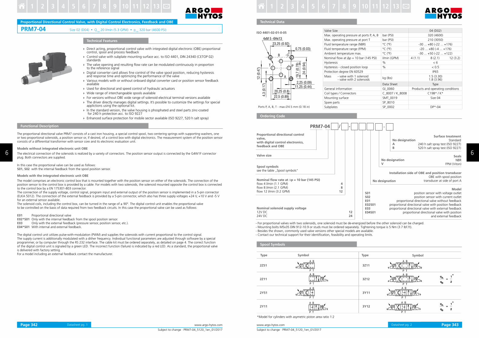
Proportional Directional Control Valve, with Analogue Control Electronics
› Direct acting, proportional control valve without or with integrated analogue electronic (OBE) with subplate mounting interface acc. to ISO 4401, DIN 24340 (CETOP 02) standards
› Used for directional and speed control of hydraulic actuators
› The valve opening and resulting low rate can be modulated continuously in proportion to the reference signal
› The valve can be controlled directly by a current control supply unit or by means of the electronic control units to exploit valve performance to the full
› Converter analogue card allow a ine control of the positioning of the valve spool, reducing hysteresis and response time and optimizing the performance of the valve
› Three chamber housing design for production cost saving
› For versions without OBE wide range of solenoid electrical terminal versions available
› Wide range of interchangeable spools and manual overrides available
› The coil is fastened to the core tube with a retaining nut and can be rotated by 360° to suit the available space
› In the standard version, the valve housing is phosphated and steel parts zinc-coated for 240 h salt spray protection acc. to ISO 9227
› Enhanced surface protection for mobile sector available (ISO 9227, 520 h salt spray)
Technical Features
Functional Description
PRM2-04* Versions without on board electronicsThe valve can be controlled directly by a current control supply unit or by means of the external electronic card directly mounted to the electrical terminal (see catalogue of EL3E card 9145 and EL6 card 9150). This control card, depending on the number of the controlled solenoids, can be mounted onto either solenoid.
PRM2-04*EK Versions with on board electronicsA control box, which comprises one or two electronic control cards, depending on the number of the controlled solenoids, can be mounted onto either solenoid. With the model with two solenoids, the solenoid mounted opposite the control box is connected with the box by means of a DIN connector, a two-cored cable and a bushing. The connection of the control box with the supply source and with the control signal is realized by means of a 4-pin connector, type M12x1. The electric control unit supplies the solenoid with current, which varies with the control signal.
The electronic control unit provides the following adjustment possibilities:Offset, gain, rise and drop-out time of the ramp generator, frequency (2 frequencies) and amplitude of the dither signal generator. The correct function of the control unit is signaled by LED-diodes. Stabilized voltage +10V (+5V for 12V voltage) is also available for the user.By the use of this voltage, a voltage control signal can be made by means of a potentiometer ≥ 1kW .The electronic control card enables voltage or current control to be used, according to the positions of the switches SW1 to SW3.
Nominal Size 04 (D02)
Max. operating pressure at port P, A, B bar (PSI) 320 (4580)
Max. operating pressure at port T bar (PSI) 210 (3050)
Fluid temperature range (NBR) °C (°F) -30 ... +80 (-22 ... +176)
Fluid temperature range (FPM) °C (°F) -20 ... +80 (-4 ... +176)
Ambient temperature range °C (°F) -30 ... +50 (-22 ... +122)
Hysteresis % ≤ 6
Nominal low rate Qn at Dp=10 bar (145 PSI) l/min (GPM) 4 (1.1 ) 8 (2.1) 12 (3.2)
Protection degree (for version PRM*EK) IP65
Mass - valve with 1 solenoid - valve with 2 solenoids
kg (lbs)0.9 (1.98) 1.25 (2.76)
Technical Data of the Proportional Solenoid
Nominal supply voltage V 12 DC 24 DC
Limit current A 1.7 0.8
Mean resistance value at 20 °C (68 °F) Ω 5 21
Technical data of the electronics Ucc 12V DC Ucc 24V DC
Supply voltage range V 11.2... 14.7 20... 30
Stabilized voltage for control V 5 DC (R >1 kW) 10 DC (R >1 kW)
Control signal see table of switches coniguration (page 4,5 and 6)
Maximum output current A 2.4 for R < 4 W 1.5 for R < 10 WRamp adjustment range s 0.05... 3
Dither frequency Hz 90 / 60
Dither amplitude % 0... 30
Data Sheet Type
General information GI_0060 products and operating conditions
Coil types / Connectors C_8007 / K_8008 C19B* / K*
Mounting interface SMT_0019 Size 04
Spare parts SP_8010
Subplates SP_0002 DP*-04
Technical Data
Datasheet pg. 1
Valve size No designationAB
Surface treatmentstandard
zinc-coated (ZnCr-3), ISO 9227 (240 h)zinc-coated (ZnNi), ISO 9227 (520 h)
1224
Rated supply voltage of solenoids (at the coil terminal)12 V DC24 V DC
Manual overridestandard
protected with rubber boot
No designationN2
Connectoronly for version without on board electronic „EK“
EN 175301-803-AE1 with quenching diode
AMP Junior Timer - axial direction E3 with quenching diode
AMP Junior Timer - axial direction (2 pins; male)E3A with quenching diode
loose conductors (two insulated wires)E8 with quenching diode
deutsch DT04-2P - axial direction (2 pins; male)E12A with quenching diode
E1E2E3E4E3AE4AE8E9E12AE13A
PRM2-04 / -
Electronics on board / Position at solenoidconnection by connector M12 x 1 (4-pin connector, supplied with counterpart)
on board electronics (solenoid „a“)
on board electronics (solenoid „b“)*
EK
EKB
Spool symbolssee table „Spool Symbols“
4 812
Nominal low rate at ∆p = 10 bar (145 PSI) 4 l/min (1.05 GPM) 8 l/min (2.1 GPM)12 l/min (3.2 GPM)
-
Spool Symbols
SealsNBR
FPM (Viton)No designationV
q
q=
1
2
*A
B
q
q=
1
2
*A
B
Type Symbol Type Symbol
2Z51 3Z11
2Z11 3Z12
2Y51 3Y11
2Y11 3Y12
Subject to change · PRM2-04_5105_1en_01/2017
www.argo-hytos.com Page 2
Ordering Code
Proportional directional control valve, with analogue control electronics
* For valve versions with one solenoid the designation „B“ with OBE is not shown.
- Valves without integrated control electronics with E1, E2 coils (with connector according to EN 175301-803, form A) are delivered in the standard version with connector sockets.- For proportional valves with two solenoids, one solenoid must be de-energized before the other solenoid can be charged.- Mounting bolts M5 x 35 DIN 912-10.9 or studs must be ordered separately. Tightening torque is 5 Nm (3.7 Ibf.ft).- Besides the shown, commonly used valve versions other specialmodels are available.- Contact our technical support for their identiication, feasibility and operating limits.
*Model for cylinders with asymetric piston area ratio 1:2
Datasheet pg. 2Page 332 Page 333
6 6
3 4 5 6 7 8 9 10 11 12 131 2 3 4 5 6 7 8 9 10 11 12 131 2
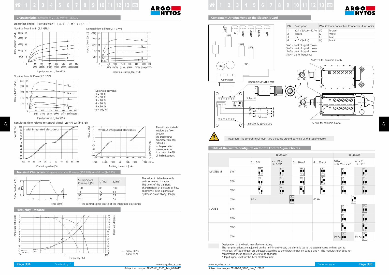
Nominal low 4 l/min (1.1 GPM)
Characteristics measured at ν = 32 mm2/s (156 SUS)
Flow
Q [
l/m
in (
GPM
)]
Nominal low 8 l/min (2.1 GPM)
Solenoid current:1 = 50 % 2 = 60 % 3 = 70 % 4 = 80 % 5 = 90 % 6 = 100 %
Nominal low 12 l/min (3.2 GPM)
Input pressure p0 [bar (PSI)]
Flow
Q [
l/m
in (
GPM
)]
Flo
w Q
[l/m
in (G
PM
)]
Flo
w Q
[%
]Spool p
osi
tio
n s
[%
]
Control signal ux [%]
Flo
w Q
[%
]
with integrated electronics
sup
ply
vo
ltag
e
Exciting current Ic [mA]
without integrated electronics
24 V
(12 V)
The coil current which initializes the low through the proportional directional valve can differ due to the production tolerances about in a range of ± 6%of the limit current.
Steady Spool Position S
s [%]
t2 [ms] t
4 [ms]
100 85 100
75 70 85
50 55 75
25 45 55
Time t [ms] ---- the control signal course of the integrated electronics
The values in table have only an informative character.The times of the transient characteristics at pressure or low control will be in a particular hydraulic circuit always longer.
Regulated low related to control signal Δp=10 bar (145 PSI)
Am
plit
ude r
atio [
dB]
Ph
ase
lag [
degre
es]
------ signal 90 % signal 25 %
Frequency Response
Transient Characteristic measured at ν = 32 mm2/s (156 SUS), Δp=10 bar (145 PSI)
Frequency [%]
Input pressure p0 [bar (PSI)]Input pressure p
0 [bar (PSI)]
Subject to change · PRM2-04_5105_1en_01/2017
www.argo-hytos.comPage 3
Operating limits: Flow direction P → A / B → T or P → B / A → T
Datasheet pg. 3
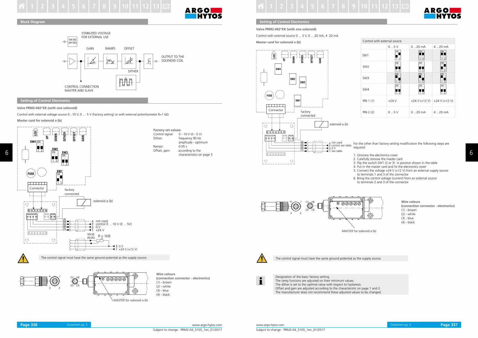
Designation of the basic manufacture setting.The ramp functions are adjusted on their minimum values, the dither is set to the optimal value with respect to hysteresis. Offset and gain are adjusted according to the characterisitic on page 3 and 4. The manufacturer does not recommend these adjusted values to be changed.* Input signal level for the 12 V electronic unit.
Subject to change · PRM2-04_5105_1en_01/2017
www.argo-hytos.com Page 4
Component Arrangement on the Electronic Card
PIN Description Wire Colours Connection Connector - Electronics
1 +24 V (Ucc) (+12 V) (1) brown
2 control (2) white
3 0 V (3) blue
4 +10 V (+5 V) (4) black
Table of the Switch Configuration for the Control Signal Choices
Attention: The control signal must have the same ground potential as the supply source.
PRM2-042 PRM2-043
0 ... 5 V0 ... 10 V (0...5 V)*
0 ... 20 mA 4 ... 20 mAUcc/2± 10 V (± 5 V)*
± 10 V (± 5 V)*
MASTER M SW1
SW2
SW3
SW4 90 Hz 60 Hz
SLAVE S SW1
SW2
SW3
SW4 60 Hz90 Hz
(4)(2)(3)(1)
4231
LED
UP
GA
IN
DO
WN
DIT
HER
OFF
SET
SW4
SW2
SW3
SW1FUSE
4 1
3 2
1
(1) (4)
(2) (3)A
(B)B
(A)
(1) (4)
(2) (3)
SLAVE for solenoid b or a
MASTER for solenoid a or b
Electronic MASTER cardConnector
Solenoid
Electronic SLAVE card
SW1 - control signal choiceSW2 - control signal choiceSW3 - control signal choiceSW4 - dither frequency
Datasheet pg. 4Page 334 Page 335
6 6
3 4 5 6 7 8 9 10 11 12 131 2 3 4 5 6 7 8 9 10 11 12 131 2
Subject to change · PRM2-04_5105_1en_01/2017
www.argo-hytos.comPage 5
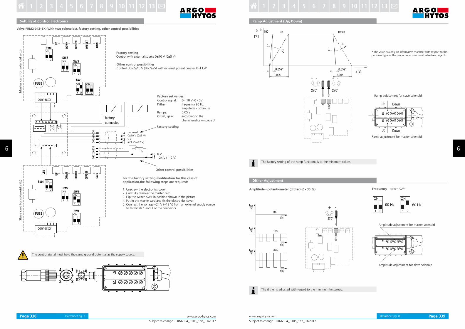
Setting of Control Electronics
Valve PRM2-042*EK (with one solenoid)
Control with external voltage source 0...10 V, 0 … 5 V (Factory setting) or with external potentiometer R>1 kW
Master card for solenoid a (b)
14
3 2
(1) (4)
(2) (3)
MASTER for solenoid a (b)
Factory set values:
Control signal: 0 - 10 V (0 - 5 V)
Dither: frequency 90 Hz
amplitude - optimum
Ramps: 0.05 s
Offset, gain: according to the
characteristics on page 3
Wire colours
(connection connector - electronics)
(1) - brown
(2) - white
(3) - blue
(4) - black
Block Diagram
10V DC
(5V DC)
STABILIZED VOLTAGEFOR EXTERNAL USE
GAIN RAMPS OFFSET
DITHER
OUTPUT TO THE SOLENOID COIL
CONTROL CONNECTIONMASTER AND SLAVE
0 V+24 V (+12 V)
R > 1kΩ
The control signal must have the same ground potential as the supply source.
(4)(2)(3)
LED
UP
GA
IN
SW4
SW2
SW3
SW1FUSE
DO
WN
DIT
HER
OFFS
ET
(1)
4231
31
10V DC
(5V DC)
not usedcontrol 0 ... 10 V (0 ... 5V)0 V+24 V
Connector factory
connected
solenoid a (b)
Datasheet pg. 5
Subject to change · PRM2-04_5105_1en_01/2017
www.argo-hytos.com Page 6
Control with external source 0 ... 5 V, 0 ... 20 mA, 4 20 mA
(4)(2)(3)
SW4
SW2
SW3
SW1
(1)
4
31
2
LED
UP
GA
IN
FUSE
DO
WN
DIT
HER
OFFS
ET
Connector factory connected
solenoid a (b)
not usedcontrol see table0 Vsee table
For the other than factory setting modiication the following steps are required:
1. Unscrew the electronics cover2. Carefully remove the master card3. Flip the switch SW1 (2 or 3) in position shown in the table4. Put in the master card and ix the electronics cover5. Connect the voltage +24 V (+12 V) from an external supply source to terminals 1 and 3 of the connector6. Bring the control voltage (current) from an external source
to terminals 2 and 3 of the connector
Master card for solenoid a (b)
Setting of Control Electronics
The control signal must have the same ground potential as the supply source.
Designation of the basic factory setting.The ramp funcions are adjusted on their minimum values.The dither is set to the optimal value with respect to hysteresis.Offset and gain are adjusted according to the characteristic on page 1 and 2.The manufacturer does not recommend these adjusted values to be changed.
14
3 2
(1) (4)
(2) (3)
MASTER for solenoid a (b)
Wire colours
(connection connector - electronics)
(1) - brown
(2) - white
(3) - blue
(4) - black
Valve PRM2-042*EK (with one solenoid)
Control with external source
0 ...5 V 0 ...20 mA 4 ...20 mA
SW1
SW2
SW3
SW4
PIN 1 (1) +24 V +24 V (+12 V) +24 V (+12 V)
PIN 2 (2) 0 ...5 V 0 ...20 mA 4 ...20 mA
Datasheet pg. 6Page 336 Page 337
6 6
3 4 5 6 7 8 9 10 11 12 131 2 3 4 5 6 7 8 9 10 11 12 131 2
Subject to change · PRM2-04_5105_1en_01/2017
www.argo-hytos.comPage 7
Setting of Control Electronics
Valve PRM2-043*EK (with two solenoids), factory setting, other control possibilities
Factory settingControl with external source 0±10 V (0±5 V)
Other control possibilitiesControl Ucc/2±10 V (Ucc/2±5) with external potentiometer R>1 kW
Factory setting
Other control possibilities
For the factory setting modiication for this case of application,the following steps are required:
1. Unscrew the electronics cover2. Carefully remove the master card3. Flip the switch SW1 in position shown in the picture4. Put in the master card and ix the electronics cover5. Connect the voltage +24 V (+12 V) from an external supply source
to terminals 1 and 3 of the connector
Factory set values:
Control signal: 0 - 10 V (0 - 5V)
Dither: frequency 90 Hz
amplitude - optimum
Ramps: 0.05 s
Offset, gain: according to the
characteristics on page 3
not used0±10 V (0±5 V)0 V+24 V (+12 V)
0 V+24 V (+12 V)
Sla
ve c
ard
fo
r so
len
oid
a (
b)
Mast
er
card
fo
r so
len
oid
a (
b)
The control signal must have the same ground potential as the supply source.
Datasheet pg. 7
Subject to change · PRM2-04_5105_1en_01/2017
www.argo-hytos.com Page 8
Ramp Adjustment (Up, Down)
* The value has only an informative character with respect to the particular type of the proportional directional valve (see page 3).
Dither Adjustment
Amplitude - potentiometer (dither) (0 - 30 %)
Amplitude adjustment for master solenoid
Amplitude adjustment for slave solenoid
Frequency - switch SW4
The factory setting of the ramp functions is to the minimum values.
The dither is adjusted with regard to the minimum hysteresis.
Ramp adjustment for slave solenoid
Ramp adjustment for master solenoid
Datasheet pg. 8Page 338 Page 339
6 6
3 4 5 6 7 8 9 10 11 12 131 2 3 4 5 6 7 8 9 10 11 12 131 2

Subject to change · PRM2-04_5105_1en_01/2017
www.argo-hytos.comPage 9
Offset, Gain Parameters Adjustment
Q[ ]%
ux %[ ] ux %[ ]
uxx uxx100 100
100
Q[ ]%100
+ +
- -
Nominal Supply Voltage of Electronics (V)
Area Insensible to Control Signal uxx (%)
12 1 ... 3
24 0,5 ... 2
Solenoid Coil in millimeters (inches)
The factory setting of the offset and gain parameters is speciic for the solenoids used.The manufacturer does not recommend this setting to be changed.
In case of solenoid malfunction or power failure, the spool of the valve can be shifted by manual override as long as the pressure in port T does not exceed 25 bar (363 PSI). For alternative manual overrides contact our technical support.
OF
FS
ET
270°
+ -
270°
+ -
GA
IN
OFFSET GAIN
Adjustment of offset Gain for master solenoid
Adjustment of offset Gain for master solenoid
37
(1
.46
)
30
(1.1
8)
49,4 (1.95)
42
(1
.65
)
45
,5 (
1.7
9)
Note:A = Standard 300 mm, (11.8 in) other lengths on demand
The indicated IP protection level is only achieved if the connector is properly mounted.
No Designation
- Standard
Designation N2
- Rubber Boot Protected
Manual Override in millimeters (inches)
65,5 (2.58)
a
72 (2.83)
a
E1, E2 Protection Degree IP65
E3, E4
Protection Degree IP67
E3A, E4A
Protection Degree IP65
E8, E9
Protection Degree IP65
E12A, E13A
Protection Degree IP67 / 69K
Datasheet pg. 9
Dimensions in millimeters (inches)
PRM2-043x/xEK*Valve with one solenoidOBE on side “a” version EK
PRM2-043x/xEK*Valve with two solenoidsOBE on side “a” version EK
Valve with one solenoid „a“Spool symbols 2Z51, 2Y51OBE on side “a” version EK
Valve with two solenoids Spool symbols 3Z11, 3Z12, 3Y11, 3Y12OBE on side “a” version EK
Valve with one solenoid „b“Spool symbols 2Z11, 2Y11
OBE on side “b” version EK
Valve with two solenoids OBE on side “b” version EKBSpool symbols 3Z11, 3Z12, 3Y11, 3Y12
PRM2-043..../..-...E1
PRM2-042.../..-...E1
Valve with one solenoid „a“ Functional symbols2Z51, 2Y51
Functional symbols3Z11, 3Z12, 3Y11, 3Y12
Valve with one solenoid „b“ Functional symbols2Z11, 2Y11
Plastic nut3+1 Nm
(2.2+0.7 lbf.ft)
Valve with two solenoids Example with electrical terminal EN 175301-803-A (E1, E2)
Subject to change · PRM2-04_5105_1en_01/2017
www.argo-hytos.com Page 10Datasheet pg. 10Page 340 Page 341
6 6
3 4 5 6 7 8 9 10 11 12 131 2 3 4 5 6 7 8 9 10 11 12 131 2
PRM7-04 Size 02 (D04) Qmax 20 l/min (5.3 GPM) p
max 320 bar (4600 PSI)
Subject to change · PRM7-04_5120_1en_01/2017
www.argo-hytos.comPage 1 Datasheet pg. 1
Proportional Directional Control Valve, with Digital Control Electronics, Feedback and OBE
Technical Features
› Direct acting, proportional control valve with integrated digital electronic (OBE) proportional control, spool and process feedback
› Control valve with subplate mounting surface acc. to ISO 4401, DIN 24340 (CETOP 02)standards
› The valve opening and resulting low rate can be modulated continuously in proportion to the reference signal
› Digital converter card allows ine control of the valve spool position, reducing hysteresis and response time and optimizing the performance of the valve
› Various models with or without onboard digital converter card or position sensor feedback available
› Used for directional and speed control of hydraulic actuators
› Wide range of interchangeable spools available
› For versions without OBE wide range of solenoid electrical terminal versions available
› The driver directly manages digital settings. It’s possible to customize the settings for special applictions using the optional kit.
› In the standard version, the valve housing is phosphated and steel parts zinc-coated for 240 h protection acc. to ISO 9227
› Enhanced surface protection for mobile sector available (ISO 9227, 520 h salt spray)
Functional Description
The proportional directional valve PRM7 consists of a cast iron housing, a special control spool, two centering springs with supporting washers, one or two proportional solenoids, a position sensor or, if desired, of a control box with digital electronics. The measurement system of the position sensor consists of a differential transformer with sensor core and its electronic evaluation unit.
Models without integrated electronic unit OBE
The electrical connection of the solenoids is realized by a variety of connectors. The position sensor output is connected by the G4W1F connector plug. Both connectors are supplied.
In this case the proportional valve can be used as follows:S01, S02 with the internal feedback from the spool position sensor.
Models with the integrated electronic unit OBE
The model comprises an electronic control box that is mounted together with the position sensor on either of the solenoids. The connection of the position sensor to the control box is provided by a cable. For models with two solenoids, the solenoid mounted opposite the control box is connected to the control box by a EN 175301-803 connector. The connection of the supply voltage, control signal, program input and external output of the position sensor is implemented in a 5-pin connector (ELKA 5012). The connection of the external feedback is provided by a 5-pin connector, which also has three supply voltages +24 V, +10 V and -5 V for an external sensor available. The solenoid coils, including the control box, can be turned in the range of ± 90°. The digital control unit enables the proportional valve to be controlled on the basis of data required from two feedback circuits. In this case the proportional valve can be used as follows:
E01 Proportional directional valveE02*S01 Only with the internal feedback from the spool position sensor.E03 Only with the external feedback (pressure sensor, position sensor, etc.).E04*S01 With internal and external feedback.
The digital control unit utilizes pulse-with-modulation (PWM) and supplies the solenoids with current proportional to the control signal.The supply current is additionally modulated with a dither frequency. Individual functional parameters are adjusted through software by a special programmer, or by computer through the RS 232 interface. The cable kit must be ordered separately, as detailed on page 4. The correct function of the digital control unit is signaled by a green LED. The incorrect function (failure) is indicated by a red LED. As a standard, the proportional valve is delivered with factory setting. For a model including an external feedback contact the manufacturer.
- For proportional valves with two solenoids, one solenoid must be de-energized before the other solenoid can be charged.- Mounting bolts M5x35 DIN 912-10.9 or studs must be ordered separately. Tightening torque is 5 Nm (3.7 Ibf.ft).- Besides the shown, commonly used valve versions other special models are available.- Contact our technical support for their identiication, feasibility and operating limits.
Spool Symbols
q
q=
1
2
*A
B
q
q=
1
2
*A
B
*Model for cylinders with asymetric piston area ratio 1:2
Type Symbol Type Symbol
2Z51 3Z11
2Z11 3Z12
2Y51 3Y11
2Y11 3Y12
Subject to change · PRM7-04_5120_1en_01/2017
www.argo-hytos.com Page 2Datasheet pg. 2
22,5 (0.89)
23,25 (0.92)
4,3
(0.1
7)
12 (
0.4
7)
19,7
(0.7
8)
11,25 (0.44)2,25 (0.09)
20,25 (0.8)
24 (
0.9
4)
0,75 (0.03)
4xM 5 -6Hx13
A
PT
BG
Ports P, A, B, T - max ∅4.5 mm (0.18 in)
ISO 4401-02-01-0-05 Valve Size 04 (D02)
Max. operating pressure at ports P, A, B bar (PSI) 320 (4600)
Max. operating pressure at port T bar (PSI) 210 (3050)
Fluid temperature range (NBR) °C (°F) -30 ... +80 (-22 ... +176)
Fluid temperature range (FPM) °C (°F) -20 ... +80 (-4 ... +176)
Ambient temperature max. °C (°F) -30 ... +50 (-22 ... +122)
Nominal low at Δp = 10 bar (145 PSI) l/min (GPM) 4 (1.1) 8 (2.1) 12 (3.2)
Hysteresis % < 6
Hysteresis - closed position loop % < 0.5
Protection degree EN 60529 IP65
Mass - valve with 1 solenoid - valve with 2 solenoids
kg (Ibs)1.5 (3.30)1.8 (3.96)
Data Sheet Type
General information GI_0060 Products and operating conditions
Coil types / Connectors C_8007 / K_8008 C19B* / K*
Mounting surface SMT_0019 Size 04
Spare parts SP_8010
Subplates SP_0002 DP*-04
PRM7-04 / -
Spool symbolssee the table „Spool symbols“
Valve size
No designationAB
Surface treatmentStandard
240 h salt spray test (ISO 9227)520 h salt spray test (ISO 9227)
1224
No designationV
Nominal solenoid supply voltage12V DC24V DC
SealsNBR
FPM (Viton)
Modelposition sensor with voltage outlet position sensor with current outlet
proportional directional valve without feedbackproportional directional valve with position feedbackproportional directional valve with external feedback
proportional directional valve with positionand external feedback
S01S02E01E02S01E03E04S01
Proportional directional controlvalve, with digital control electronics, feedback and OBE
Nominal low rate at Dp = 10 bar (145 PSI)low 4 l/min (1.1 GPM)low 8 l/min (2.1 GPM)low 12 l/min (3.2 GPM)
48
12
No designation
Installation side of OBE and position transducerOBE with spool position
transducer at side of port A
Ordering Code
Technical Data
Page 342 Page 343
6 6
3 4 5 6 7 8 9 10 11 12 131 2 3 4 5 6 7 8 9 10 11 12 131 2

Subject to change · PRM7-04_5120_1en_01/2017
www.argo-hytos.comPage 3 Datasheet pg. 3
Technical Data of Position Sensor - Voltage Outlet
Operating pressure bar (PSI) to 320 (4640), static
Electrical connection * only for S01 model electrical connector G4W1F Hirschmann*
Contact assigment
1 - Power supply2 - Command signal
3 - GND4 - not used
Enclosure protection type according to EN 60529 IP65
Measured distance mm (in) 8 (0.315)
Operating voltage V 9.6 ... 30 DC
Linearity error % < 1
Current consumption at load current of 2 mA mA < 15
Output voltage V 0 ... 5Output signal range used:0 position1 solenoid - stroke 1.8 mm (0.07 in)2 solenoids - stroke ±1.8 mm (0.07 in)
V2.5
1.375 ... 2.51.375 ... 3.625
Max. load current mA 2
Noise voltage - at load current 0 - at load current of 2 mA
mVp-p
< 20< 15
Additional output signal error at:- temperature change between 0 ... 80°C (32... 176 °F)- between 0... -25 °C (32 ... -13 °F)- Load change from 0 to 2 mA
typical 0.2% / 10Kmax. 0.5 % / 10Kmax. 0.5 % / 10K
0.1 %Input voltage changefrom 9.6 V to 14.4 Vfrom 14.4 V to 30 V
%< 0.1
< 0.25
Long-term drift (30 days) % < 0.25Cut-off frequency3dB fall in amplitudeFrequency 90°
Hz> 600> 600
Technical Data of Position Sensor - Current Outlet
Linearity % < 1
Operating pressure bar (PSI) to 320 (4640), static
Electrical connection * only for S02 model electrical connector G4W1F Hirschmann*
Contact assigment
1 - Power supply2 - Command signal
3 - GND4 - not used
Enclosure protection type according to EN 60529 IP 65
Operatin voltage V 20 ... 30 DC
Current mA < 35
Output signal range mA 4 ... 20
Output signal range used:0 position1 solenoid - stroke 1.8mm (0.07 in)2 solenoids - stroke ±1.8 mm (0.07 in)
mA12
8.4 ... 128.4 ... 15.6
Additional output signal error:- at temperature change from +10... 55°C (50... 131°F)- at imjpedance change from 50%- at input voltage change in the range of operating voltage
0.2% / 10K≤ 0.1%≤ 0.05%
Impedance Ω ≤ 500
Output signal ripple mA R.M.S. ≤ 0.02
Limit frequency at 3 dB amplitude decrease Hz ≥ 800
Technical Data of Proportional Solenoid
Type of coil V 12 DC 24 DC
Limiting current A 1.7 0.8
Resistance at 20° C (68 °F) Ω 4.9 21
Electronics Data
Supply voltage with polarity inversion protection V 11.2 ... 28 VDC (residual ripple < 10%)
Input: command signal / according to customer setting ±10 V, 0...10 V, ±10 mA, 4...20 mA, 0...20 mA, 12 mA ±8 mA
Input: spool position sensor signal 0...5V
Input: external feedback signal 0...10 V, 4...20 mA, 0...20 mA
Resolution of the A/D converter 12 bit
Output: solenoids two PWM output stages up to max. 3.5 A
PWM frequency kHz 18
Adjustment of parameters μS 170
EMCInterference resistance 61000 - 6 - 2 : 2005
Radiation resistance 55011 : 1998 class A
Parameter setting Serial port RS 232 (zero modem). 19200 bauds, 8 data bits, 1 stop bit, no parity. Special software PRM7 Conf.
Subject to change · PRM7-04_5120_1en_01/2017
www.argo-hytos.com Page 4Datasheet pg. 4
Order number Content
23093400 Connecting cable to PC - length 2 m (6.56 ft), CD-ROM with program PRM7 Conf and user manual
23093500 Connecting cable to PC - length 5 m (16.40 ft), CD-ROM with program PRM7 Conf and user manual
24523400 Connecting cable to PC - length 2 m (6.56 ft)
24523500 Connecting cable to PC - length 5 m (6.56 ft)
Accessories
-7-8-9
-10-11
-12-13-14
10
-1-2-3-4-5-6
-15
10
1009080706050
4030
160150140130120110
20100
1001
-16-17
180170
signal 25%signal 90%
Frequency Response closed position loop, for E02S01 model
Am
plit
ude r
atio [dB]
Frequency [Hz]
Phase
lag [degre
es]
Nominal low 4 l/min (1.1 GPM)
Flow
Q [l/m
in (G
PM
)]
Nominal low 8 l/min (2.1 GPM
Solenoid current:1 = 50% 2 = 60 % 3 = 70 % 4 = 80 % 5 = 90 % 6 = 100 %
Nominal low 12 l/min (3.2 GPM)
Input pressure po [bar (PSI)]
Input pressure po [bar (PSI)]
Input pressure po [bar (PSI)]
Flow
Q [l/m
in (G
PM
)]
Flow
Q [l/m
in (G
PM
)]
Charactersitics measured at ν = 32 mm2/s (156 SUS)
Control signal ux [%]
Regulated low related to control signal
Flow characteristics (E01 model only) Δp=10 bar (145 PSI)
Flow
Q [%
]
Operating limits: Flow direction P → A / B → T or P → B / A → T
Operating limits only for E01 model only
Page 344 Page 345
6 6
3 4 5 6 7 8 9 10 11 12 131 2 3 4 5 6 7 8 9 10 11 12 131 2

Connector K2 - type M12x1 (male)
PIN Technical data
1 TxD
2 RxD
3 Ground (signal)
4 Not used
4
21
5 3
K3 Connector K3 - type M12x1 (female)
PIN Technical data
1 Power supply output
2 Signal of external feedback
3 Ground
4 Not used
5 Not used
K3
3
12
4
K2K2
K1 Connector K1 - type M23 (male)
PIN Technical data
1 * Power supply input
2 * Ground (power supply)
3 Control signal
4 Ground (signal)
5 Power reference signal
6 Control signal of position sensor spool
7 * Protective earth lead (PE)
*Recommended min. lead cross section 0,75 mm2
K2 - Connection RS232 M12x1 (4 PIN) To program the electronics.
K1 - Main inplut connector M23 (7PIN)Cable diameter 8 ...12 mm (0.31...0.47 in).
K3 - Conektor M12x1 (5PIN) External feedback signal (for conigurations E03
and E04S01 only).
Subject to change · PRM7-04_5120_1en_01/2017
www.argo-hytos.comPage 5 Datasheet pg. 5
Flow Characteristics measured at ν = 32 mm2/s (156 SUS)
Factory Settings
Connectors
Model
Item E01 E02S01 E03 E04S01
1 Magnet 2 Magnets 1 Magnet 2 Magnets 1 Magnet 2 Magnets 1 Magnet 2 Magnets
Control signal 0 ... 10 V ± 10 V 0 ... 10 V ± 10 V 0 ... 10 V ± 10 V 0 ... 10 V ± 10 V
Signal external feedback - - - 0 ... 10 V
Output position sensor spool - 0 ... 5 V - 0 ... 5 V
Dp = Valve pressure differential (inlet pressure pV minus load
pressure and return pressure pT)
Dpn = Valve pressure differential for nominal low Q
n)
Flow
Q [l/m
in (G
PM
)]
Command value [%]
Qn = 12 l/min (3.2 GPM) by Dp = 10 bar (145 PSI)
1 Dpn = 10 bar (145 PSI)
2 Dp = 50 bar (725 PSI)
3 Dp = 160 bar (2321 PSI)
4 Dp = 320 bar (4641 PSI)
Qn = 8 l/min (2.1 GPM) by Dp = 10 bar (145 PSI)Q
n = 4 l/min (1.1 GPM) by Dp = 10 bar (145 PSI)
Flow
Q [l/m
in (G
PM
)]
Flow
Q [l/m
in (G
PM
)]
Command value [%]Command value [%]
Flow characteristics (E02S01 model only) PRM7-043 ... S01
PRM7-043 ... S02
PRM7-043 ... E01 - without connector plug for spool position feedback
PRM7-043 ... E03
PRM7-043 ... E02S01 - without connector plug for spool position feedback
PRM7-043 ... E04S01
1 Solenoid a2 Solenoid b3 Manual override4 Name plate5 4 mounting holes6 Solenoid ixing nut7 Connector M12x1 for connection
of external feedback8 Main supply connector M239 Square ring 7.65 x 1.68 (4 pcs.),
supplied in delivery packet10 Cover of connector M12x1
for programming11 Plastic box with integrated
electronics12 Position sensor
Subject to change · PRM7-04_5120_1en_01/2017
www.argo-hytos.com Page 6Datasheet pg. 6
Dimensions in millimeters (inches)
Page 346 Page 347
6 6
3 4 5 6 7 8 9 10 11 12 131 2 3 4 5 6 7 8 9 10 11 12 131 2

PRM2-06 Size 06 (D03) Qmax
40 l/min (11 GPM) • pmax
350 bar (5100 PSI)
T P
B
A
G
0,75 (0.03)
4xM5-6Hx13
15,5 (0.61)
31,75 (1.25)
5,1 (0.20)
25,9 (1.16)
31 (1.22)
12
,7 (
0.5
0)
21
,5 (
0.8
5)
30
,2 (
1.1
8)
40
,5 (
1.5
9)
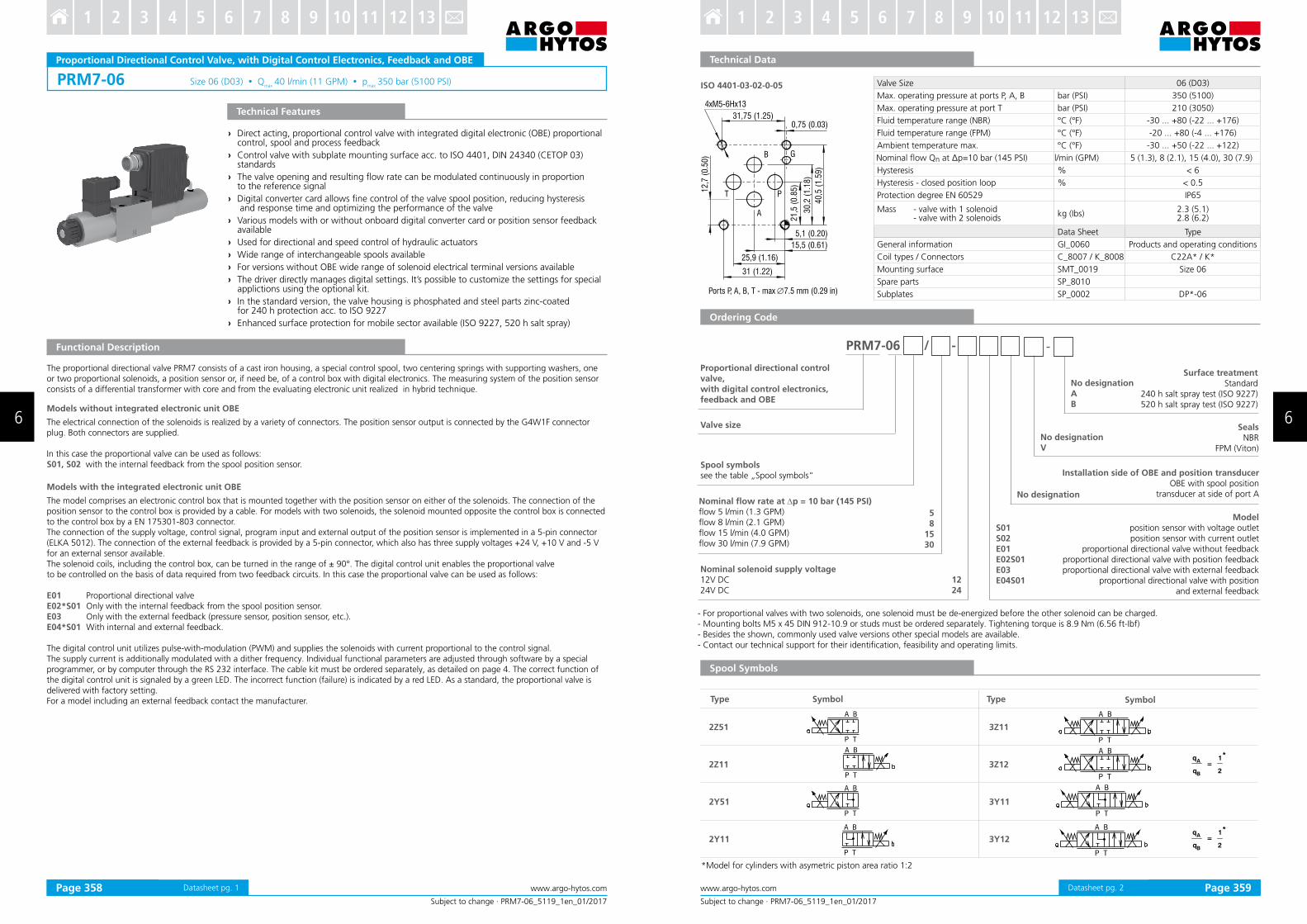
ISO 4401-03-02-0-05
Ports P, A, B, T - max ∅7.5 mm (0.29 in)
Subject to change · PRM2-06_5104_1en_01/2017
www.argo-hytos.comPage 1
Proportional Directional Control Valve, with Analog Control Electronics
› Direct acting, proportional control valve without or with integrated analog electronic (OBE) with subplate mounting surface acc. to ISO 4401, DIN 24340 (CETOP 03) standards
› Used for directional and speed control of hydraulic actuators
› The valve opening and resulting low rate can be modulated continuously in proportion to the reference signal
› The valve can be controlled directly by a current control supply unit or by means of the electronic control units to exploit valve performance to the fullest
› Analog converter card allows ine control of the valve spool position, reducing hysteresis and response time and optimizing the valve performance
› Five chambers housing design with reduced hydraulic power dependence on luid viscosity
› For versions without OBE a wide range of solenoid electrical terminal versions available
› Wide range of interchangeable spools and manual overrides available
› The coil is fastened to the core tube with a retaining nut and can be rotated by 360° to suit the available space
› In the standard version, the valve housing is phosphated and steel parts are zinc-coated for 240 h salt spray protection acc. to ISO 9227
› Enhanced surface protection for mobile sector available (ISO 9227, 520 h salt spray)
Technical Features
Functional Description
PRM2-06* Versions without on board electronicsThe valve can be controlled directly by a current control supply unit or by the external electronic card directly mounted to the electrical terminal (see catalog of EL3E card 9145 and EL6 card 9150). This control card, depending on the number of the controlled solenoids, can be mounted onto either solenoid.
PRM2-06*EK Versions with on board electronicsA control box, which comprises one or two electronic control cards, depending on the number of controlled solenoids, can be mounted onto either solenoid. For models with two solenoids, the solenoid mounted opposite the control box is connected to the box by a DIN connector, a two-lead cable and a bushing. The connection of the control box with the supply source and with the control signal is implemented by a 4-pin connector of type M12x1.The electric control unit supplies the solenoid with current, which varies with the control signal.
The electronic control unit provides the following adjustment possibilities:Offset, gain, rise and drop-out time of the ramp generator, frequency (2 frequencies) and amplitude of the dither signal generator.The correct function of the control unit is signaled by LEDs. Stabilized voltage +10 V (+5 V for 12 V voltage) is also available to the user.Using this voltage and a potentiometer ≥ 1kW a voltage control signal can be generated.The electronic control card enables voltage or current control to be used, depending on the position of the switches SW1 to SW3.
Nominal Size 06 (D03)
Max. operating pressure at port P, A, B bar (PSI) 350 (5080)
Max. operating pressure at port T bar (PSI) 210 (3050)
Fluid temperature range (NBR) °C (°F) -30 ... +80 (-22 ... +176)
Fluid temperature range (FPM) °C (°F) -20 ... +80 (-4 ... +176)
Ambient temperature range °C (°F) -30 ... +50 (-22 ... +122)
Hysteresis % ≤ 6
Nominal low rate Qn at Dp=10 bar (145 PSI) l/min (GPM) 5 (1.13) 8 (2.1) 15 (4.0) 30 (7.9)
Protection degree (for version PRM*EK) IP65
Mass - valve with 1 solenoid - valve with 2 solenoids
kg (lbs)1.9 (4.2) 2.4 (5.3)
Technical Data of the Proportional Solenoid
Nominal supply voltage V 12 DC 24 DC
Limit currentA
2.5 1.0
- with electronic 1.6 -
Mean resistance value at 20 °C (68 °F)Ω
2.3 13.4
- with electronic 5.2 -
Technical Data of the Electronics V Ucc 12V DC Ucc 24V DC
Supply voltage range V 11.2... 14.7 20... 30
Stabilized voltage for control V 5 DC (R >1 kW) 10 DC (R >1 kW)
Control signal see table of switches coniguration (page 4, 5 and 6)
Maximum output current A 2.4 for R < 4 W 1.5 for R < 10 WRamp adjustment range s 0.05... 3
Dither frequency Hz 90 / 60
Dither amplitude % 0... 30
Data Sheet Type
General information GI_0060 Products and operating conditions
Coil types / Connectors C_8007 / K_8008 C22B* / K*
Mounting interface / Tolerances SMT_0019 Size 06
Spare parts SP_8010
Subplates SP_0002 DP*-06
Technical Data
Datasheet pg. 1
Subject to change · PRM2-06_5104_1en_01/2017
www.argo-hytos.com Page 2
Valve size
Surface treatmentstandard
zinc-coated (ZnCr-3), ISO 9227 (240 h) zinc-coated (ZnNi), ISO 9227 (520 h)
1224
Rated supply voltage of solenoids (at the coil terminal)12 V DC24 V DC
Manual Overridestandard
protected with cap nutprotected with rubber boot
No designationN1N2
Connectoronly for version without on board electronic „EK“
with terminal for the connector, EN 175301-803-AE1 with quenching diode
with AMP-Junior-Timer-connector - Axial direction E3A with quenching diode
loose conductors (two insulated wires)E8 with quenching diode
with Deutsch DT04-2PE12A with quenching diode
E1E2E3AE4AE8E9E12AE13A
PRM2-06 / -
SealsNBR
FPM (Viton)
No designationV
Electronics on board / Position at solenoidconnection by connector M12 x 1 (4-pin connector, supplied with counterpart)
on board electronics (solenoid „a“)
on board electronics (solenoid „b“)*
EK
EKB
*For valve versions with one solenoid the designation „B“ with OBE is not shown.
- For proportional valves with two solenoids, one solenoid must be de-energized before the other solenoid can be charged. - Mounting bolts M5 x 45 DIN 912-10.9 or studs must be ordered separately. Tightening torque is 8.9 Nm (6.56 ft-Ibf) - Besides the shown, commonly used valve versions other special models are available. - Contact our technical support for their identiication, feasibility and operating limits.
Spool symbolssee table „Spool Symbols“
5 81530
-
Spool Symbols
Ordering Code
Proportional directional control valve, with analog control electronics
*Model for cylinders with asymetric piston area ratio 1:2
Nominal low rate at ∆p = 10 bar (145 PSI) 5 l/min (1.3 GPM) 8 l/min (2.1 GPM)15 l/min (4.0 GPM)30 l/min (7.9 GPM)
q
q=
1
2
*A
B
q
q=
1
2
*A
B
Type Symbol Type Symbol
2Z51 3Z11
2Z11 3Z12
2Y51 3Y11
2Y11 3Y12
No designationAB
Datasheet pg. 2Page 348 Page 349
6 6
3 4 5 6 7 8 9 10 11 12 131 2 3 4 5 6 7 8 9 10 11 12 131 2
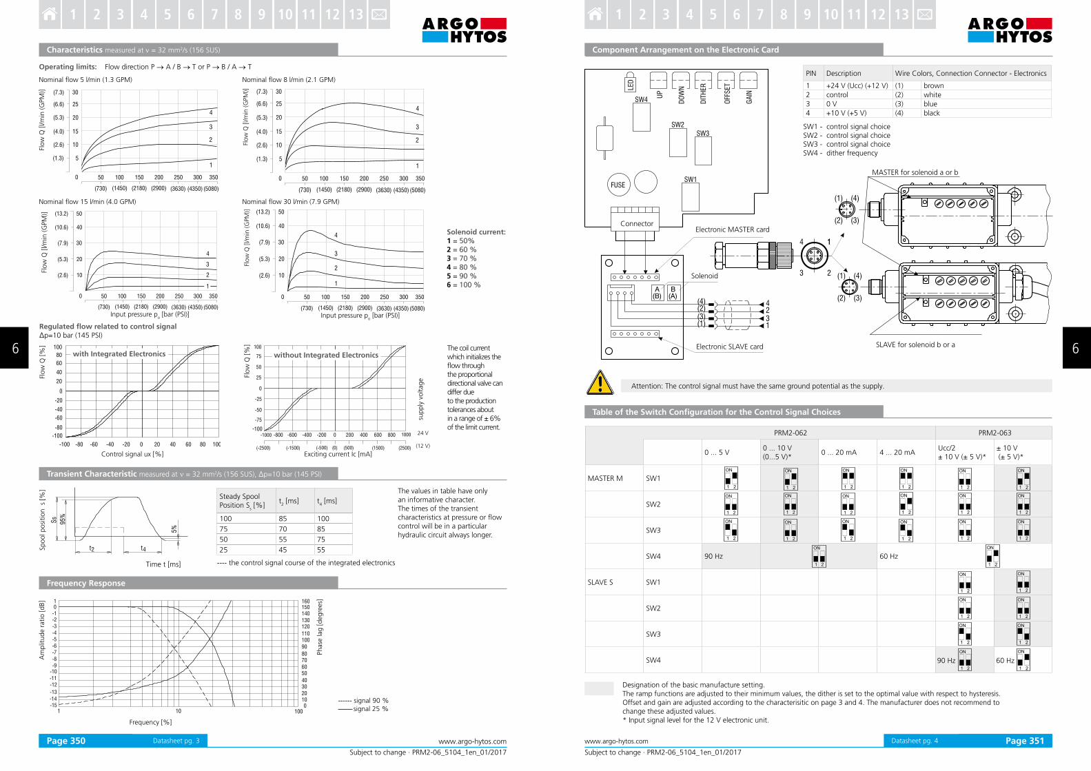
Nominal low 5 l/min (1.3 GPM)
Characteristics measured at ν = 32 mm2/s (156 SUS)
Flow
Q [
l/m
in (
GPM
)]
Nominal low 8 l/min (2.1 GPM)
Operating limits: Flow direction P → A / B → T or P → B / A → T
Solenoid current:1 = 50% 2 = 60 % 3 = 70 % 4 = 80 % 5 = 90 % 6 = 100 %
Nominal low 30 l/min (7.9 GPM)
Input pressure po [bar (PSI)]
Nominal low 15 l/min (4.0 GPM)
Input pressure po [bar (PSI)]
Flow
Q [
l/m
in (
GPM
)]
Flo
w Q
[l/m
in (G
PM
)]Fl
ow
Q [l/m
in (G
PM
)]
Subject to change · PRM2-06_5104_1en_01/2017
www.argo-hytos.comPage 3
Flo
w Q
[%
]Spool p
osi
tio
n s
[%]
Control signal ux [%]
Flo
w Q
[%
]
with Integrated Electronics
sup
ply
vo
ltag
e
Exciting current Ic [mA]
without Integrated Electronics
24 V
(12 V)
The coil current which initializes the low through the proportional directional valve can differ due to the production tolerances about in a range of ± 6%of the limit current.
Steady Spool Position S
s [%]
t2 [ms] t
4 [ms]
100 85 100
75 70 85
50 55 75
25 45 55
Time t [ms] ---- the control signal course of the integrated electronics
The values in table have only an informative character.The times of the transient characteristics at pressure or low control will be in a particular hydraulic circuit always longer.
Regulated low related to control signal Δp=10 bar (145 PSI)
Am
plit
ude r
atio [
dB]
Phase
lag [
degre
es]
------ signal 90 % signal 25 %
Frequency Response
Transient Characteristic measured at ν = 32 mm2/s (156 SUS), Δp=10 bar (145 PSI)
Frequency [%]
Datasheet pg. 3
Subject to change · PRM2-06_5104_1en_01/2017
www.argo-hytos.com Page 4
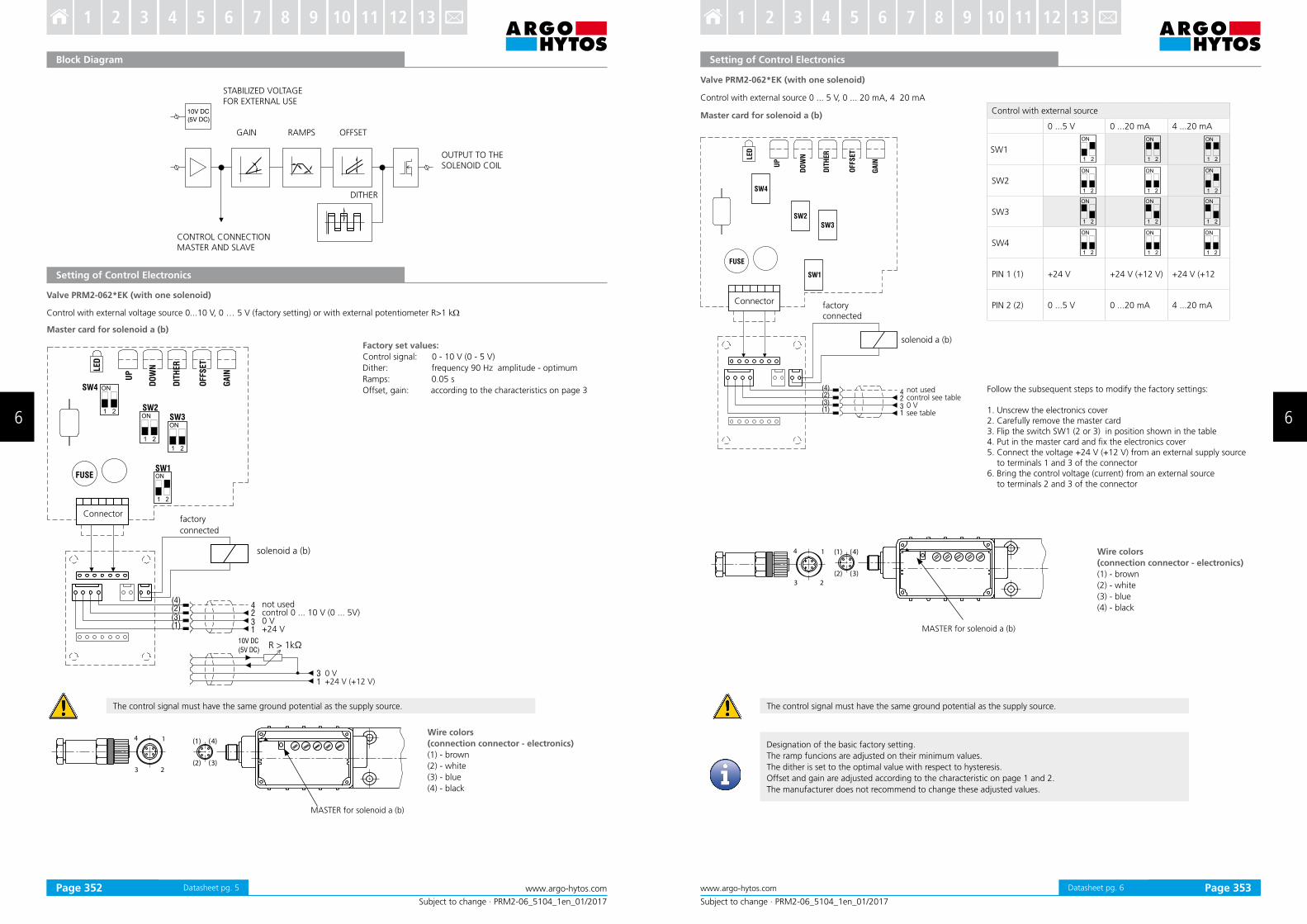
Component Arrangement on the Electronic Card
Table of the Switch Configuration for the Control Signal Choices
Attention: The control signal must have the same ground potential as the supply.
Designation of the basic manufacture setting.The ramp functions are adjusted to their minimum values, the dither is set to the optimal value with respect to hysteresis. Offset and gain are adjusted according to the characterisitic on page 3 and 4. The manufacturer does not recommend to change these adjusted values.* Input signal level for the 12 V electronic unit.
PRM2-062 PRM2-063
0 ... 5 V0 ... 10 V (0...5 V)*
0 ... 20 mA 4 ... 20 mAUcc/2± 10 V (± 5 V)*
± 10 V (± 5 V)*
MASTER M SW1
SW2
SW3
SW4 90 Hz 60 Hz
SLAVE S SW1
SW2
SW3
SW4 60 Hz90 Hz
PIN Description Wire Colors, Connection Connector - Electronics
1 +24 V (Ucc) (+12 V) (1) brown
2 control (2) white
3 0 V (3) blue
4 +10 V (+5 V) (4) black
(4)(2)(3)(1)
4231
LED
UP
GA
IN
DO
WN
DIT
HER
OFF
SET
SW4
SW2
SW3
SW1FUSE
4 1
3 2
1
(1) (4)
(2) (3)A
(B)B
(A)
(1) (4)
(2) (3)
SLAVE for solenoid b or a
MASTER for solenoid a or b
Connector
Solenoid
Electronic SLAVE card
SW1 - control signal choiceSW2 - control signal choiceSW3 - control signal choiceSW4 - dither frequency
Electronic MASTER card
Datasheet pg. 4Page 350 Page 351
6 6
3 4 5 6 7 8 9 10 11 12 131 2 3 4 5 6 7 8 9 10 11 12 131 2
Subject to change · PRM2-06_5104_1en_01/2017
www.argo-hytos.comPage 5
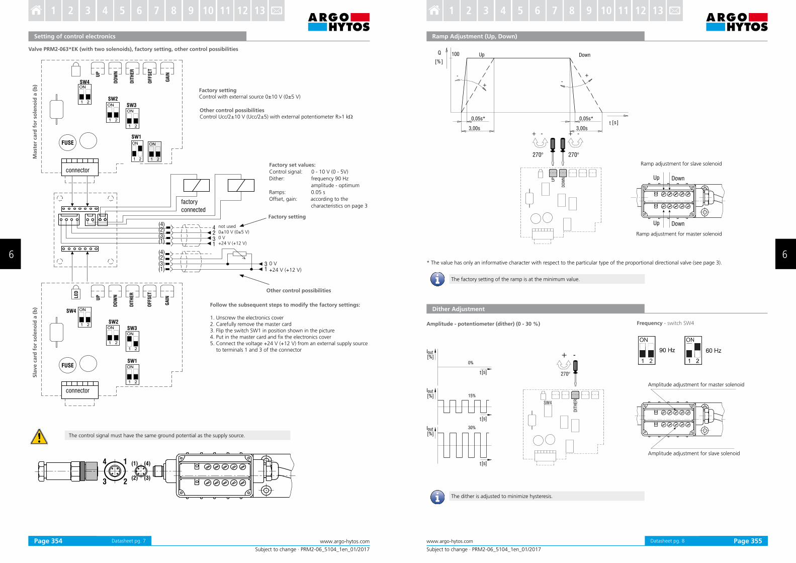
Setting of Control Electronics
Valve PRM2-062*EK (with one solenoid)
Control with external voltage source 0...10 V, 0 … 5 V (factory setting) or with external potentiometer R>1 kW
Master card for solenoid a (b)
14
3 2
(1) (4)
(2) (3)
MASTER for solenoid a (b)
Connectorfactory
connected
solenoid a (b)
Factory set values:
Control signal: 0 - 10 V (0 - 5 V)
Dither: frequency 90 Hz amplitude - optimum
Ramps: 0.05 s
Offset, gain: according to the characteristics on page 3
Wire colors
(connection connector - electronics)
(1) - brown
(2) - white
(3) - blue
(4) - black
Block Diagram
10V DC
(5V DC)
STABILIZED VOLTAGEFOR EXTERNAL USE
GAIN RAMPS OFFSET
DITHER
OUTPUT TO THE SOLENOID COIL
CONTROL CONNECTIONMASTER AND SLAVE
not usedcontrol 0 ... 10 V (0 ... 5V)0 V+24 V
0 V+24 V (+12 V)
R > 1kΩ
The control signal must have the same ground potential as the supply source.
Datasheet pg. 5
Subject to change · PRM2-06_5104_1en_01/2017
www.argo-hytos.com Page 6
Control with external source 0 ... 5 V, 0 ... 20 mA, 4 20 mA
(4)(2)(3)
SW4
SW2
SW3
SW1
(1)
4
31
2
LED
UP
GA
IN
FUSE
DO
WN
DIT
HER
OFFS
ET
Connector factory connected
solenoid a (b)
not usedcontrol see table0 Vsee table
Follow the subsequent steps to modify the factory settings:
1. Unscrew the electronics cover2. Carefully remove the master card3. Flip the switch SW1 (2 or 3) in position shown in the table4. Put in the master card and ix the electronics cover5. Connect the voltage +24 V (+12 V) from an external supply source to terminals 1 and 3 of the connector6. Bring the control voltage (current) from an external source
to terminals 2 and 3 of the connector
Master card for solenoid a (b)
Setting of Control Electronics
The control signal must have the same ground potential as the supply source.
Designation of the basic factory setting.
The ramp funcions are adjusted on their minimum values.
The dither is set to the optimal value with respect to hysteresis.
Offset and gain are adjusted according to the characteristic on page 1 and 2.
The manufacturer does not recommend to change these adjusted values.
14
3 2
(1) (4)
(2) (3)
MASTER for solenoid a (b)
Wire colors
(connection connector - electronics)
(1) - brown
(2) - white
(3) - blue
(4) - black
Valve PRM2-062*EK (with one solenoid)
Control with external source
0 ...5 V 0 ...20 mA 4 ...20 mA
SW1
SW2
SW3
SW4
PIN 1 (1) +24 V +24 V (+12 V) +24 V (+12
PIN 2 (2) 0 ...5 V 0 ...20 mA 4 ...20 mA
Datasheet pg. 6Page 352 Page 353
6 6
3 4 5 6 7 8 9 10 11 12 131 2 3 4 5 6 7 8 9 10 11 12 131 2
Subject to change · PRM2-06_5104_1en_01/2017
www.argo-hytos.comPage 7
Setting of control electronics
Valve PRM2-063*EK (with two solenoids), factory setting, other control possibilities
Factory settingControl with external source 0±10 V (0±5 V)
Other control possibilitiesControl Ucc/2±10 V (Ucc/2±5) with external potentiometer R>1 kW
Factory setting
Other control possibilities
Follow the subsequent steps to modify the factory settings:
1. Unscrew the electronics cover2. Carefully remove the master card3. Flip the switch SW1 in position shown in the picture4. Put in the master card and ix the electronics cover5. Connect the voltage +24 V (+12 V) from an external supply source
to terminals 1 and 3 of the connector
Factory set values:
Control signal: 0 - 10 V (0 - 5V)
Dither: frequency 90 Hz
amplitude - optimum
Ramps: 0.05 s
Offset, gain: according to the
characteristics on page 3
not used0±10 V (0±5 V)0 V+24 V (+12 V)
0 V+24 V (+12 V)
Sla
ve c
ard
fo
r so
len
oid
a (
b)
Mast
er
card
fo
r so
len
oid
a (
b)
The control signal must have the same ground potential as the supply source.
Datasheet pg. 7
Subject to change · PRM2-06_5104_1en_01/2017
www.argo-hytos.com Page 8
Ramp Adjustment (Up, Down)
* The value has only an informative character with respect to the particular type of the proportional directional valve (see page 3).
Dither Adjustment
Amplitude - potentiometer (dither) (0 - 30 %)
Amplitude adjustment for master solenoid
Amplitude adjustment for slave solenoid
Frequency - switch SW4
The factory setting of the ramp is at the minimum value.
The dither is adjusted to minimize hysteresis.
Ramp adjustment for slave solenoid
Ramp adjustment for master solenoid
Datasheet pg. 8Page 354 Page 355
6 6
3 4 5 6 7 8 9 10 11 12 131 2 3 4 5 6 7 8 9 10 11 12 131 2
Subject to change · PRM2-06_5104_1en_01/2017
www.argo-hytos.comPage 9
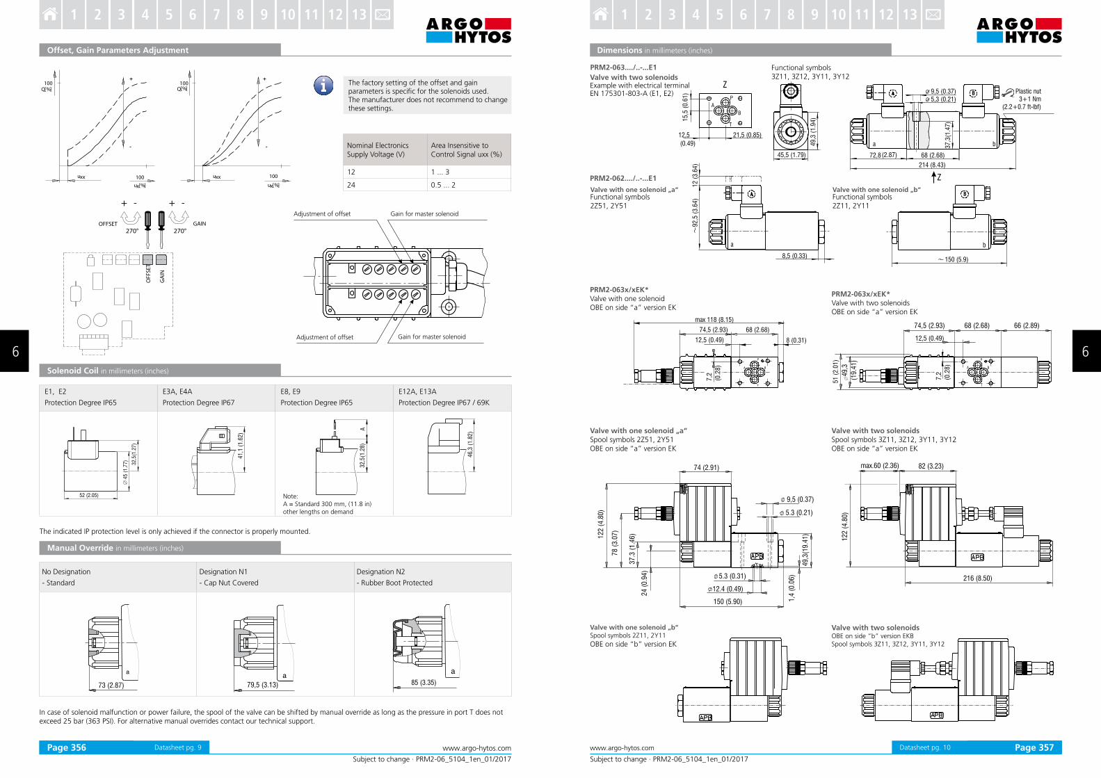
Offset, Gain Parameters Adjustment
Q[ ]%
ux %[ ] ux %[ ]
uxx uxx100 100
100
Q[ ]%100
+ +
- - Nominal Electronics Supply Voltage (V)
Area Insensitive to Control Signal uxx (%)
12 1 ... 3
24 0.5 ... 2
Solenoid Coil in millimeters (inches)
The factory setting of the offset and gain parameters is speciic for the solenoids used.The manufacturer does not recommend to change these settings.
In case of solenoid malfunction or power failure, the spool of the valve can be shifted by manual override as long as the pressure in port T does not exceed 25 bar (363 PSI). For alternative manual overrides contact our technical support.
OF
FS
ET
270°
+ -
270°
+ -
GA
IN
OFFSET GAIN
45
77
)(1
.
32
,5(1
.27
)
52 (2.05)
41
,1 (
1.6
2)
32
,5(1
.28
)A
46
,3 (
1.8
2)
Note:A = Standard 300 mm, (11.8 in) other lengths on demand
The indicated IP protection level is only achieved if the connector is properly mounted.
No Designation
- Standard
Designation N1
- Cap Nut Covered
Designation N2
- Rubber Boot Protected
Manual Override in millimeters (inches)
a
73 (2.87) 79,5 (3.13)
a85 (3.35)
a
E1, E2 Protection Degree IP65
E3A, E4A
Protection Degree IP67
E8, E9
Protection Degree IP65
E12A, E13A
Protection Degree IP67 / 69K
Adjustment of offset Gain for master solenoid
Adjustment of offset Gain for master solenoid
Datasheet pg. 9
Subject to change · PRM2-06_5104_1en_01/2017
www.argo-hytos.com Page 10
Dimensions in millimeters (inches)
PRM2-063x/xEK*Valve with one solenoidOBE on side “a” version EK
PRM2-063x/xEK*Valve with two solenoidsOBE on side “a” version EK
Valve with one solenoid „a“Spool symbols 2Z51, 2Y51OBE on side “a” version EK
Valve with two solenoids Spool symbols 3Z11, 3Z12, 3Y11, 3Y12OBE on side “a” version EK
Valve with one solenoid „b“Spool symbols 2Z11, 2Y11
OBE on side “b” version EK
Valve with two solenoids OBE on side “b” version EKBSpool symbols 3Z11, 3Z12, 3Y11, 3Y12
PRM2-063..../..-...E1
PRM2-062..../..-...E1
Valve with two solenoids Example with electrical terminal EN 175301-803-A (E1, E2)
Valve with one solenoid „a“ Functional symbols2Z51, 2Y51
Functional symbols3Z11, 3Z12, 3Y11, 3Y12
Valve with one solenoid „b“ Functional symbols2Z11, 2Y11
Plastic nut3+1 Nm
(2.2+0.7 ft-lbf)
Datasheet pg. 10Page 356 Page 357
6 6
3 4 5 6 7 8 9 10 11 12 131 2 3 4 5 6 7 8 9 10 11 12 131 2
PRM7-06 Size 06 (D03) Qmax 40 l/min (11 GPM) p
max 350 bar (5100 PSI)
Subject to change · PRM7-06_5119_1en_01/2017
www.argo-hytos.comPage 1 Datasheet pg. 1
Proportional Directional Control Valve, with Digital Control Electronics, Feedback and OBE
› Direct acting, proportional control valve with integrated digital electronic (OBE) proportional control, spool and process feedback
› Control valve with subplate mounting surface acc. to ISO 4401, DIN 24340 (CETOP 03)standards
› The valve opening and resulting low rate can be modulated continuously in proportion to the reference signal
› Digital converter card allows ine control of the valve spool position, reducing hysteresis and response time and optimizing the performance of the valve
› Various models with or without onboard digital converter card or position sensor feedback available
› Used for directional and speed control of hydraulic actuators
› Wide range of interchangeable spools available
› For versions without OBE wide range of solenoid electrical terminal versions available
› The driver directly manages digital settings. It’s possible to customize the settings for special applictions using the optional kit.
› In the standard version, the valve housing is phosphated and steel parts zinc-coated for 240 h protection acc. to ISO 9227
› Enhanced surface protection for mobile sector available (ISO 9227, 520 h salt spray)
Functional Description
The proportional directional valve PRM7 consists of a cast iron housing, a special control spool, two centering springs with supporting washers, one or two proportional solenoids, a position sensor or, if need be, of a control box with digital electronics. The measuring system of the position sensor consists of a differential transformer with core and from the evaluating electronic unit realized in hybrid technique.
Models without integrated electronic unit OBE
The electrical connection of the solenoids is realized by a variety of connectors. The position sensor output is connected by the G4W1F connector plug. Both connectors are supplied.
In this case the proportional valve can be used as follows:S01, S02 with the internal feedback from the spool position sensor.
Models with the integrated electronic unit OBE
The model comprises an electronic control box that is mounted together with the position sensor on either of the solenoids. The connection of the position sensor to the control box is provided by a cable. For models with two solenoids, the solenoid mounted opposite the control box is connected to the control box by a EN 175301-803 connector. The connection of the supply voltage, control signal, program input and external output of the position sensor is implemented in a 5-pin connector (ELKA 5012). The connection of the external feedback is provided by a 5-pin connector, which also has three supply voltages +24 V, +10 V and -5 V for an external sensor available. The solenoid coils, including the control box, can be turned in the range of ± 90°. The digital control unit enables the proportional valve to be controlled on the basis of data required from two feedback circuits. In this case the proportional valve can be used as follows:
E01 Proportional directional valveE02*S01 Only with the internal feedback from the spool position sensor.E03 Only with the external feedback (pressure sensor, position sensor, etc.).E04*S01 With internal and external feedback.
The digital control unit utilizes pulse-with-modulation (PWM) and supplies the solenoids with current proportional to the control signal.The supply current is additionally modulated with a dither frequency. Individual functional parameters are adjusted through software by a special programmer, or by computer through the RS 232 interface. The cable kit must be ordered separately, as detailed on page 4. The correct function of the digital control unit is signaled by a green LED. The incorrect function (failure) is indicated by a red LED. As a standard, the proportional valve is delivered with factory setting. For a model including an external feedback contact the manufacturer.
Technical Features
Subject to change · PRM7-06_5119_1en_01/2017
www.argo-hytos.com Page 2Datasheet pg. 2
Valve Size 06 (D03)
Max. operating pressure at ports P, A, B bar (PSI) 350 (5100)
Max. operating pressure at port T bar (PSI) 210 (3050)
Fluid temperature range (NBR) °C (°F) -30 ... +80 (-22 ... +176)
Fluid temperature range (FPM) °C (°F) -20 ... +80 (-4 ... +176)
Ambient temperature max. °C (°F) -30 ... +50 (-22 ... +122)
Nominal low Qn at ∆p=10 bar (145 PSI) l/min (GPM) 5 (1.3), 8 (2.1), 15 (4.0), 30 (7.9)
Hysteresis % < 6
Hysteresis - closed position loop % < 0.5
Protection degree EN 60529 IP65
Mass - valve with 1 solenoid - valve with 2 solenoids
kg (Ibs)2.3 (5.1)2.8 (6.2)
Data Sheet Type
General information GI_0060 Products and operating conditions
Coil types / Connectors C_8007 / K_8008 C22A* / K*
Mounting surface SMT_0019 Size 06
Spare parts SP_8010
Subplates SP_0002 DP*-06
T P
B
A
G
0,75 (0.03)
4xM5-6Hx13
15,5 (0.61)
31,75 (1.25)
5,1 (0.20)
25,9 (1.16)
31 (1.22)
12
,7 (
0.5
0)
21
,5 (
0.8
5)
30
,2 (
1.1
8)
40
,5 (
1.5
9)
ISO 4401-03-02-0-05
Technical Data
Nominal low rate at Dp = 10 bar (145 PSI)low 5 l/min (1.3 GPM)low 8 l/min (2.1 GPM)low 15 l/min (4.0 GPM)low 30 l/min (7.9 GPM)
58
1530
- For proportional valves with two solenoids, one solenoid must be de-energized before the other solenoid can be charged. - Mounting bolts M5 x 45 DIN 912-10.9 or studs must be ordered separately. Tightening torque is 8.9 Nm (6.56 ft-Ibf) - Besides the shown, commonly used valve versions other special models are available. - Contact our technical support for their identiication, feasibility and operating limits.
Spool Symbols
Ordering Code
PRM7-06 / -
Spool symbolssee the table „Spool symbols“
Valve size
No designationAB
Surface treatmentStandard
240 h salt spray test (ISO 9227)520 h salt spray test (ISO 9227)
1224
No designationV
Nominal solenoid supply voltage12V DC24V DC
SealsNBR
FPM (Viton)
Modelposition sensor with voltage outlet position sensor with current outlet
proportional directional valve without feedbackproportional directional valve with position feedbackproportional directional valve with external feedback
proportional directional valve with positionand external feedback
S01S02E01E02S01E03E04S01
Proportional directional controlvalve, with digital control electronics, feedback and OBE
No designation
Installation side of OBE and position transducerOBE with spool position
transducer at side of port A
Ports P, A, B, T - max ∅7.5 mm (0.29 in)
*Model for cylinders with asymetric piston area ratio 1:2
q
q=
1
2
*A
B
q
q=
1
2
*A
B
Type Symbol Type Symbol
2Z51 3Z11
2Z11 3Z12
2Y51 3Y11
2Y11 3Y12
Page 358 Page 359
6 6
3 4 5 6 7 8 9 10 11 12 131 2 3 4 5 6 7 8 9 10 11 12 131 2
Subject to change · PRM7-06_5119_1en_01/2017
www.argo-hytos.comPage 3 Datasheet pg. 3
Technical Data of Position Sensor - Voltage Outlet
Operating pressure bar (PSI) to 350 (5100), static
Electrical connection * only for S01 model electrical connector G4W1F Hirschmann*
Contact assigment
1 - Power supply2 - Command signal
3 - GND4 - not used
Enclosure protection type according to EN 60529 IP65
Measured distance mm (in) 8 (0.315)
Operating voltage V 9.6 ... 30 DC
Linearity error % < 1
Current consumption at load current of 2 mA mA < 15
Output voltage V 0 ... 5
Output signal range used:0 position1 solenoid - stroke 2.8 mm (0.11 in)2 solenoids - stroke ± 2.8 mm (0.11 in)
V2.5
0.75 ... 2.50.75 ... 4.025
Max. load current mA 2Noise voltage - at load current 0 - at load current of 2 mA
mVp-p
< 20< 15
Additional output signal error at:- temperature change between 0 ... 80°C (32... 176 °F)- between 0 ... -25 °C (32 ... -13 °F)- Load change from 0 to 2 mA
typical 0.2% / 10Kmax. 0.5 % / 10Kmax. 0.5 % / 10K
0.1 %
Input voltage changefrom 9.6 V to 14.4 Vfrom 14.4 V to 30 V
%< 0.1
< 0.25
Long-term drift (30 days) % < 0.25
Cut-off frequency3dB fall in amplitudeFrequency 90°
Hz> 600> 600
Technical Data of Position Sensor - Current Outlet
Linearity % < 1
Operating pressure bar (PSI) to 350 (5100), static
Electrical connection * only for S01 and S02 model electrical connector G4W1F Hirschmann*
Contact assigment
1 - Power supply2 - Command signal
3 - GND4 - not used
Enclosure protection type according to EN 60529 IP65
Operatin voltage V 20 ... 30 DC
Current mA < 35
Output signal range mA 4 ... 20Output signal range used:0 position1 solenoid - stroke 2.8 mm (0.11 in)2 solenoids - stroke ±2.8 mm (0.11 in)
mA12
4.4 ... 124.4 ... 19.6
Additional output signal error:- at temperature change from +10 ... 55°C (50... 131°F)- at imjpedance change from 50%- at input voltage change in the range of operating voltage
0.2% / 10K≤ 0.1%
≤ 0.05%
Impedance Ω ≤ 500
Output signal ripple mA R.M.S. ≤ 0.02
Limit frequency at 3 dB amplitude decrease Hz ≥ 800
Technical Data of Proportional Solenoid
Type of coil V 12 DC 24 DC
Limiting current A 2.4 1.0
Resistance at 20 °C (68 °F) Ω 2.3 13.4
Supply voltage with polarity inversion protection V 11.2 ... 28 VDC (residual ripple < 10%)
Input: command signal / according to customer setting ±10 V, 0...10 V, ±10 mA, 4...20 mA, 0...20 mA, 12 mA±8 mA
Input: spool position sensor signal 0...5 V
Input: external feedback signal 0...10V, 4...20 mA, 0...20 mA
Resolution of the A/D converter 12 bit
Output: solenoids two PWM output stages up to max. 3.5 A
PWM frequency kHz 18
Adjustment of parameters μS 170
EMCInterference resistance 61000 - 6 - 2 : 2005
Radiation resistance 55011 : 1998 class A
Parameter setting Serial port RS 232 (zero modem). 19200 bauds, 8 data bits, 1 stop bit, no parity. Special software PRM7 Conf.
Electronics Data
Subject to change · PRM7-06_5119_1en_01/2017
www.argo-hytos.com Page 4Datasheet pg. 4
Order number Content
23093400 Connecting cable to PC - length 2 m (6.56 ft), CD-ROM with program PRM7 Conf and user manual
23093500 Connecting cable to PC - length 5 m (16.40 ft), CD-ROM with program PRM7 Conf and user manual
24523400 Connecting cable to PC - length size 2 m (6.56 ft)
24523500 Connecting cable to PC - length size 5 m (6.56 ft)
Accessories
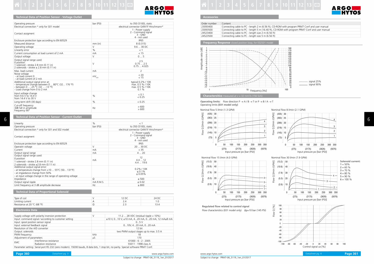
Nominal low 5 l/min (1.3 GPM)
5
10
15
20
25
30
4
3
2
1
0 50 100 150 200 250 300 350
(275) (2175) (3626) (5076)
( )218
( )290
( )145
( )363
( )435
( )73
Nominal low 8 l/min (2.1 GPM)
Operating limits: Flow direction P → A / B → T or P → B / A → T
Input pressure po [bar (PSI)]
Flow
Q [l/m
in (G
PM
)]
Charactersitics measured at ν = 32 mm2/s (156 SUS)
Nominal low 15 l/min (4.0 GPM)
20
30
40
50
0 50 100 150 200 250 300 350
(275) (2175) (3626) (5076)
( )5.3
( )7.9
( )2.6
( )13.2
10
( )10.6
4
3
21
Nominal low 30 l/min (7.9 GPM)
Input pressure po [bar (PSI)]
Flow
Q [l/m
in (G
PM
)]
5
10
15
20
25
30
4
3
2
1
0 50 100 150 200 250 300 350
(275) (2175) (3626) (5076)
( )218
( )290
( )145
( )363
( )435
( )73
Input pressure po [bar (PSI)]
10
20
30
40
50
0 50 100 150 200 250 300 350
(275) (2175) (3626) (5076)
( )5.3
( )7.9
( )2.6
( )10.6
( )13.2
4
3
21
Input pressure po [bar (PSI)]Fl
ow
Q [l/m
in (G
PM
)]Fl
ow
Q [l/m
in (G
PM
)]
-100 -80 -60 -40 -20 0 20 40 60 80 100
20
40
60
80
100
0
-20
-40
-60
-80
-100
Control signal ux [%]
Regulated low related to control signal
Flow characteristics (E01 model only) Δp=10 bar (145 PSI)
Flow
Q [%
]
Solenoid current:1 = 50% 2 = 60 % 3 = 70 % 4 = 80 % 5 = 90 % 6 = 100 %
Frequency Response closed position loop, for E02S01 model
Am
plit
ude r
atio [dB]
Frequency [Hz]
signal 25%signal 90%
Operating limits (E01 model only)
Page 360 Page 361
6 6
3 4 5 6 7 8 9 10 11 12 131 2 3 4 5 6 7 8 9 10 11 12 131 2

Subject to change · PRM7-06_5119_1en_01/2017
www.argo-hytos.comPage 5 Datasheet pg. 5
Flow
Q [l/m
in (G
PM
)]Fl
ow
Q [l/m
in (G
PM
)]
Qn = 8 l/min (2.1GPM) by Dp = 10 bar (145 PSI)
Qn = 30 l/min (7.9 GPM) by Dp = 10 bar (145 PSI)
Flow
Q [l/m
in (G
PM
)]Fl
ow
Q [l/m
in (G
PM
)]
Dp = Valve pressure differential (inlet pressure pV minus load pressure
and return pressure pT)
Dpn = Valve pressure differential for nominal low Q
n)
1 Dpn = 10 bar (145 PSI) 3 Dp = 160 bar (2321 PSI)
2 Dp = 50 bar (725 PSI) 4 Dp = 320 bar (4641 PSI)
Flow characteristics (E02S01 model only)
Qn = 5 ll/min (1.3 GPM) by Dp = 10 bar (145 PSI)
Qn = 15 ll/min (4.0 GPM) by Dp = 10 bar (145 PSI)
-100 -80 -60 -40 -20 0 20 40 60 80 100
10
20
30
40
0
- 01
- 02
- 03
- 04
5.3
10 6.
0
- .2 6
-1 .0 6
7 9.
2 6.
- .7 9
- .5 3
3
2
1
5013 2.
6015 8.
- 05-1 .3 2- 06-1 .5 8
4
Command value [%] Command value [%]
Command value [%]
Connector K2 - type M12x1 (male)
PIN Technical data
1 TxD
2 RxD
3 Ground (signal)
4 Not used
4
21
5 3
K3 Connector K3 - type M12x1 (female)
PIN Technical data
1 Power supply output
2 Signal of external feedback
3 Ground
4 Not used
5 Not used
K3
3
12
4
K2K2
K1 Connector K1 - type M23 (male)
PIN Technical data
1 * Power supply input
2 * Ground (power supply)
3 Control signal
4 Ground (signal)
5 Power reference signal
6 Control signal of position sensor spool
7 * Protective earth lead (PE)
*Recommended min. lead cross section 0.75 mm2
a b
K2 - Connection RS232 M12x1 (4 PIN) To program the electronics.
K1 - Main inplut connector M23 (7 PIN)Cable diameter 8 ...12 mm (0.31...0.47 in).
K3 - Conektor M12x1 (5 PIN) External feedback signal (for conigurations E03
and E04S01 only).
Factory Settings
Flow Characteristics measured at ν = 32 mm2/s (156 SUS)
Connectors
Model
Item E01 E02S01 E03 E04S01
1 Magnet 2 Magnets 1 Magnet 2 Magnets 1 Magnet 2 Magnets 1 Magnet 2 Magnets
Control signal 0 ... 10 V ± 10 V 0 ... 10 V ± 10 V 0 ... 10 V ± 10 V 0 ... 10 V ± 10 V
Signal external feedback - - - 0 ... 10 V
Output position sensor spool - 0 ... 5 V - 0 ... 5 V
-100 -80 -60 -40 -20 0 20 40 60 80 100
10
20
30
40
0
- 01
- 02
- 03
- 04
5.3
10 6.
0
- .2 6
-1 .0 6
7 9.
2 6.
- .7 9
- .5 3
4
3 2
1
Command value [%]
PRM7-063 ... S01
PRM7-063 ... S02
PRM7-063 ... E01 - without connector plug for spool position feedback
PRM7-063 ... E03
PRM7-063 ... E02S01 - without connector plug for spool position feedback
PRM7-063 ... E04S01
1 Solenoid a2 Solenoid b3 Manual override4 Name plate5 4 mounting holes6 Solenoid ixing nut7 Connector M12x1 for connection
of external feedback8 Main supply connector M239 Square ring 7.65 x 1.68 (4 pcs.),
supplied in delivery packet10 Cover of connector M12x1
for programming11 Plastic box with integrated
electronics12 Position sensor
Subject to change · PRM7-06_5119_1en_01/2017
www.argo-hytos.com Page 6Datasheet pg. 6
Dimensions in millimeters (inches)
Page 362 Page 363
6 6
3 4 5 6 7 8 9 10 11 12 131 2 3 4 5 6 7 8 9 10 11 12 131 2
PRM6-10 Size 10 (D05) Qmax
80 l/min (21 GPM) • pmax
350 bar (5100 PSI)
13,5(0.53)
24,6(0.97)
39,7(1.56)
46(1.81)
16,7
(0.6
6)
27(1
.06)
37,3
(1.4
7)
50,8
(2)
54(2
.13)
3,2
(0.1
3)
4xM6 -6H
x15+1/18-2 TAA
B
P
TB
Ports P, A, B, T - max. ∅11.2 mm (0.44 in)
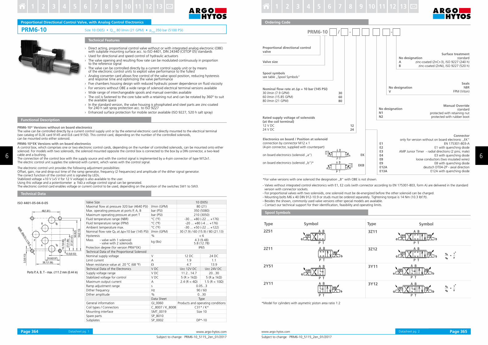
ISO 4401-05-04-0-05
Subject to change · PRM6-10_5115_2en_01/2017
www.argo-hytos.comPage 1
Proportional Directional Control Valve, with Analog Control Electronics
› Direct acting, proportional control valve without or with integrated analog electronic (OBE) with subplate mounting surface acc. to ISO 4401, DIN 24340 (CETOP 05) standards
› Used for directional and speed control of hydraulic actuators
› The valve opening and resulting low rate can be modulated continuously in proportion to the reference signal
› The valve can be controlled directly by a current control supply unit or by means of the electronic control units to exploit valve performance to the fullest
› Analog converter card allows ine control of the valve spool position, reducing hysteresis and response time and optimizing the valve performance
› Five chambers housing design with reduced hydraulic power dependence on luid viscosity
› For versions without OBE a wide range of solenoid electrical terminal versions available
› Wide range of interchangeable spools and manual overrides available
› The coil is fastened to the core tube with a retaining nut and can be rotated by 360° to suit the available space
› In the standard version, the valve housing is phosphated and steel parts are zinc-coated for 240 h salt spray protection acc. to ISO 9227
› Enhanced surface protection for mobile sector available (ISO 9227, 520 h salt spray)
Technical Features
Functional Description
PRM6-10* Versions without on board electronicsThe valve can be controlled directly by a current control supply unit or by the external electronic card directly mounted to the electrical terminal (see catalog of EL3E card 9145 and EL6 card 9150). This control card, depending on the number of the controlled solenoids, can be mounted onto either solenoid.
PRM6-10*EK Versions with on board electronicsA control box, which comprises one or two electronic control cards, depending on the number of controlled solenoids, can be mounted onto either solenoid. For models with two solenoids, the solenoid mounted opposite the control box is connected to the box by a DIN connector, a two-lead cable and a bushing.The connection of the control box with the supply source and with the control signal is implemented by a 4-pin connector of type M12x1.The electric control unit supplies the solenoid with current, which varies with the control signal.
The electronic control unit provides the following adjustment possibilities:Offset, gain, rise and drop-out time of the ramp generator, frequency (2 frequencies) and amplitude of the dither signal generator.The correct function of the control unit is signaled by LEDs.Stabilized voltage +10 V (+5 V for 12 V voltage) is also available to the user.Using this voltage and a potentiometer ≥ 1kW a voltage control signal can be generated.The electronic control card enables voltage or current control to be used, depending on the position of the switches SW1 to SW3.
Technical Data
Valve Size 10 (D05)
Maximal low at pressure 320 bar (4640 PSI) l/min (GPM) 80 (21)
Max. operating pressure at ports P, A, B bar (PSI) 350 (5080)
Maximum operating pressure at port T bar (PSI) 210 (3050)
Fluid temperature range (NBR) °C (°F) -30 ... +80 (-22 ... +176)
Fluid temperature range (FPM) °C (°F) -20 ... +80 (-4 ... +176)
Ambient temperature max. °C (°F) -30 ... +50 (-22 ... +122)
Nominal low rate Qn at Dp=10 bar (145 PSI) l/min (GPM) 30 (7.9) / 60 (15.9) / 80 (21.13)
Hysteresis % < 6
Mass - valve with 1 solenoid - valve with 2 solenoids
kg (Ibs)4.3 (9.48)5.8 (12.78)
Protection degree (for version PRM*EK) IP65
Technical Data of the Proportional Solenoid
Nominal supply voltage V 12 DC 24 DC
Limit current A 1.9 1.1
Mean resistance value at 20 °C (68 °F) W 4.7 13.9
Technical Data of the Electronics V DC Ucc 12V DC Ucc 24V DC
Supply voltage range V DC 11.2...14.7 20...30
Stabilized voltage for control V DC 5 (R > 1kΩ) 5 (R ≥ 1kΩ)
Maximum output current A 2.4 (R < 4Ω) 1.5 (R < 10Ω)
Ramp adjustment range s 0.05...3
Dither frequency Hz 90 / 60
Dither amplitude % 0...30
Data Sheet Type
General information GI_0060 Products and operating conditions
Coil types / Connectors C_8007 / K_8008 C31* / K*
Mounting interface SMT_0019 Size 10
Spare parts SP_8010
Subplates SP_0002 DP*-10
Datasheet pg. 1
12
24
E1
E2E3E4E8E9E12AE13A
PRM6-10 / - -
306080
EK
EKB
Subject to change · PRM6-10_5115_2en_01/2017
www.argo-hytos.com Page 2
Ordering Code
- Valves without integrated control electronics with E1, E2 coils (with connector according to EN 175301-803, form A) are delivered in the standard version with connector sockets.- For proportional valves with two solenoids, one solenoid must be de-energized before the other solenoid can be charged. - Mounting bolts M6 x 40 DIN 912-10.9 or studs must be ordered separately. Tightening torque is 14 Nm (10.3 Ibf.ft). - Besides the shown, commonly used valve versions other special models are available. - Contact our technical support for their identiication, feasibility and operating limits.
Spool Symbols
q
q=
1
2
*A
B
q
q=
1
2
*A
B
*Model for cylinders with asymetric piston area ratio 1:2
Type Symbol Type Symbol
2Z51 3Z11
2Z11 3Z12
2Y51 3Y11
2Y11 3Y12
Proportional directional control valve
Valve size
Spool symbolssee table „Spool Symbols“
Nominal low rate at ∆p = 10 bar (145 PSI)30 l/min (7.9 GPM)60 l/min (15.85 GPM)80 l/min (21 GPM)
Rated supply voltage of solenoids (at the coil terminal)12 V DC24 V DC
Electronics on board / Position at solenoidconnection by connector M12 x 1(4-pin connector, supplied with counterpart)
on board electronics (solenoid „a“)
on board electronics (solenoid „b“)*
*For valve versions with one solenoid the designation „B“ with OBE is not shown.
Connectoronly for version without on board electronic „EK“
EN 175301-803-AE1 with quenching diode
AMP Junior Timer - radial directions (2 pins; male)E3 with quenching diode
loose conductors (two insulated wires)E8 with quenching diode
deutsch DT04-2P - axial directionE12A with quenching diode
Manual Overridestandard
protected with retaining nutprotected with rubber boot
No designationN1N2
SealsNBR
FPM (Viton)No designationV
Surface treatmentstandard
zinc-coated (ZnCr-3), ISO 9227 (240 h)zinc-coated (ZnNi), ISO 9227 (520 h)
No designationAB
Datasheet pg. 2Page 364 Page 365
6 6
3 4 5 6 7 8 9 10 11 12 131 2 3 4 5 6 7 8 9 10 11 12 131 2

Subject to change · PRM6-10_5115_2en_01/2017
www.argo-hytos.comPage 3
Nominal low 30 l/min (7.95 GPM)
Characteristics measured at ν = 32 mm2/s (156 SUS)
Flow
Q [
l/m
in (
GPM
)]
Nominal low 60 l/min (15.85 GPM)
Operating limits: Flow direction P → A / B → T or P → B / A → T
Solenoid current:1 = 40 % 2 = 60 % 3 = 80 % 4 = 100 %
Nominal low 80 l/min (21.13 GPM)
Input pressure p0 [bar (PSI)]
Flow
Q [
l/m
in (
GPM
)]
Flo
w Q
[l/m
in (G
PM
)]
Flo
w Q
[%
]Spool po
sitio
n s
[%]
Control signal ux [%]
Flo
w Q
[%
]
with integrated electronics
sup
ply
vo
ltag
e
Exciting current Ic [mA]
without integrated electronics
24 V
(12 V)
The coil current which initializes the low through the proportional directional valve can differ due to the production tolerances about in a range of ± 6%of the limit current.
Steady Spool Position S
s [%]
t2 [ms] t
4 [ms]
100 85 100
75 70 85
50 55 75
25 45 55
Time t [ms] ---- the control signal course of the integrated electronics
The values in table have onlyan informative character.The times of the transient characteristics at pressure or low control will be in a particular hydraulic circuit always longer.
Regulated low related to control signal Δp=10 bar (145 PSI)
Am
plit
ude r
atio [
dB]
Phase
lag [
degre
es]
------ signal 90 % signal 25 %
Frequency Response
Transient Characteristic measured at ν = 32 mm2/s (156 SUS), Δp=10 bar (145 PSI)
Frequency [%]
Input pressure p0 [bar (PSI)]Input pressure p
0 [bar (PSI)]
Datasheet pg. 3
(4)(2)(3)(1)
4231
LED
UP
GA
IN
DO
WN
DIT
HER
OFF
SET
SW4
SW2
SW3
SW1FUSE
4 1
3 2
1
(1) (4)
(2) (3)A
(B)B
(A)
(1) (4)
(2) (3)
Subject to change · PRM6-10_5115_2en_01/2017
www.argo-hytos.com Page 4
Component Arrangement on the Electronic Card
Attention: The control signal must have the same ground potential as the supply source.
Designation of the basic manufacture setting.The ramp functions are adjusted on their minimum values, the dither is set to the optimal value with respect to hysteresis. Offset and gain are adjusted according to the characterisitic on page 3 and 4. The manufacturer does not recommend to change these adjusted values.* Input signal level for the 12 V electronic unit.
Table of the Switch Configuration for the Control Signal Choices
PRM2-062 PRM2-063
0 ... 5 V0 ... 10 V (0...5 V)*
0 ... 20 mA 4 ... 20 mAUcc/2±10 V (±5 V)*
±10 V (±5 V)*
MASTER M SW1
SW2
SW3
SW4 90 Hz 60 Hz
SLAVE S SW1
SW2
SW3
SW4 60 Hz90 Hz
PIN Description Wire Colors Connection Connector - Electronics
1 +24 V (Ucc) (+12 V) (1) brown
2 control (2) white
3 0 V (3) blue
4 +10 V (+5 V) (4) black
SLAVE for solenoid b or a
MASTER for solenoid a or b
Electronic MASTER card
Connector
Solenoid
Electronic SLAVE card
SW1 - control signal choiceSW2 - control signal choiceSW3 - control signal choiceSW4 - dither frequency
Datasheet pg. 4Page 366 Page 367
6 6
3 4 5 6 7 8 9 10 11 12 131 2 3 4 5 6 7 8 9 10 11 12 131 2
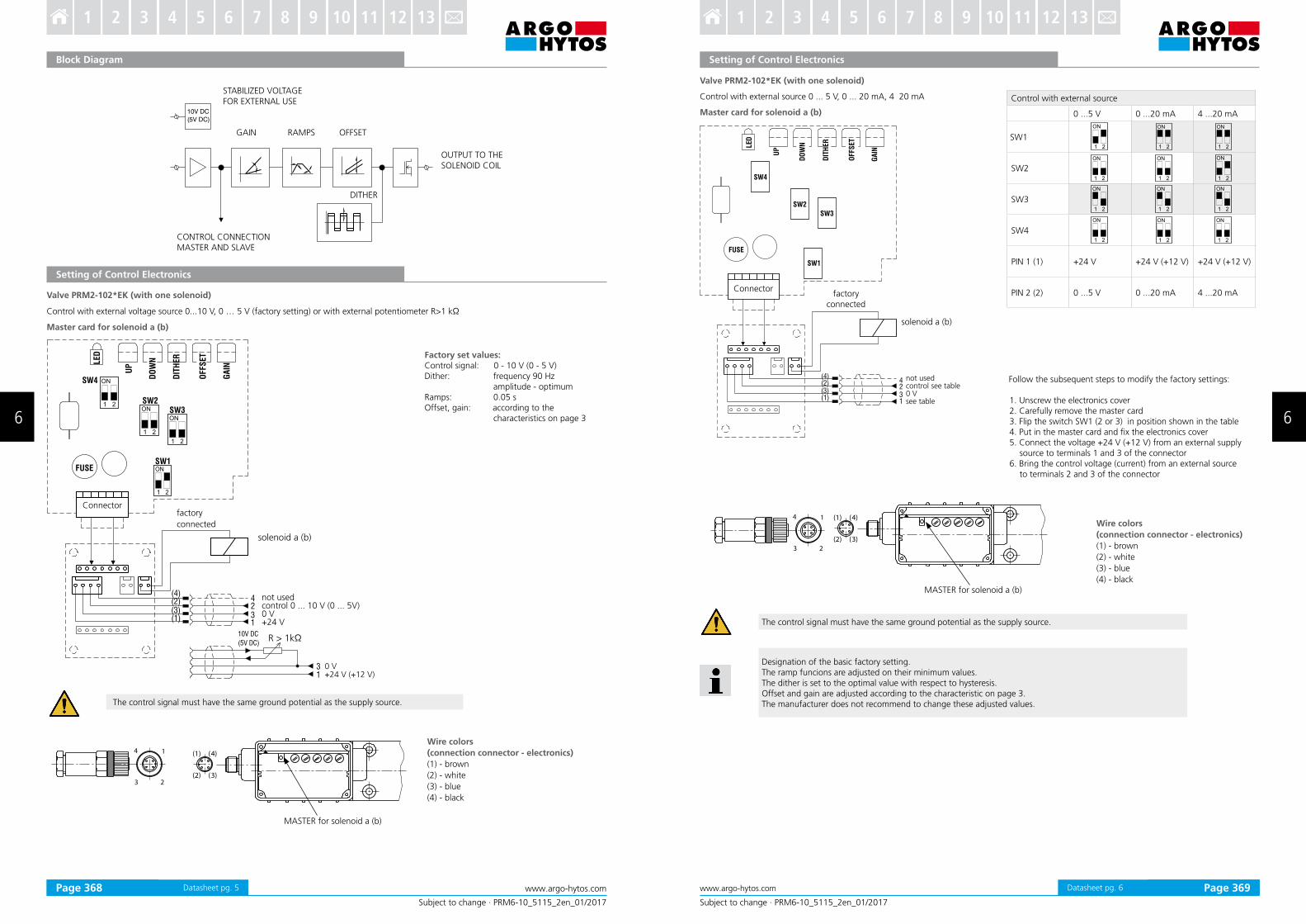
10V DC
(5V DC)
14
3 2
(1) (4)
(2) (3)
Subject to change · PRM6-10_5115_2en_01/2017
www.argo-hytos.comPage 5
Setting of Control Electronics
Valve PRM2-102*EK (with one solenoid)
Control with external voltage source 0...10 V, 0 … 5 V (factory setting) or with external potentiometer R>1 kΩ
Master card for solenoid a (b)
Connectorfactory
connected
solenoid a (b)
Factory set values:Control signal: 0 - 10 V (0 - 5 V)Dither: frequency 90 Hz amplitude - optimumRamps: 0.05 sOffset, gain: according to the characteristics on page 3
Wire colors
(connection connector - electronics)
(1) - brown
(2) - white
(3) - blue
(4) - black
Block Diagram
STABILIZED VOLTAGEFOR EXTERNAL USE
GAIN RAMPS OFFSET
DITHER
OUTPUT TO THE SOLENOID COIL
CONTROL CONNECTIONMASTER AND SLAVE
not usedcontrol 0 ... 10 V (0 ... 5V)0 V+24 V
0 V+24 V (+12 V)
R > 1kΩ
The control signal must have the same ground potential as the supply source.
MASTER for solenoid a (b)
Datasheet pg. 5
(4)(2)(3)
SW4
SW2
SW3
SW1
(1)
4
31
2
LED
UP
GA
IN
FUSE
DO
WN
DIT
HER
OFFS
ET
14
3 2
(1) (4)
(2) (3)
Subject to change · PRM6-10_5115_2en_01/2017
www.argo-hytos.com Page 6
Control with external source 0 ... 5 V, 0 ... 20 mA, 4 20 mA
Connectorfactory
connected
solenoid a (b)
not usedcontrol see table0 Vsee table
Follow the subsequent steps to modify the factory settings:
1. Unscrew the electronics cover2. Carefully remove the master card3. Flip the switch SW1 (2 or 3) in position shown in the table4. Put in the master card and ix the electronics cover5. Connect the voltage +24 V (+12 V) from an external supply source to terminals 1 and 3 of the connector6. Bring the control voltage (current) from an external source to terminals 2 and 3 of the connector
Master card for solenoid a (b)
Setting of Control Electronics
The control signal must have the same ground potential as the supply source.
Designation of the basic factory setting.The ramp funcions are adjusted on their minimum values.The dither is set to the optimal value with respect to hysteresis.Offset and gain are adjusted according to the characteristic on page 3.The manufacturer does not recommend to change these adjusted values.
Wire colors
(connection connector - electronics)
(1) - brown
(2) - white
(3) - blue
(4) - black
Valve PRM2-102*EK (with one solenoid)
Control with external source
0 ...5 V 0 ...20 mA 4 ...20 mA
SW1
SW2
SW3
SW4
PIN 1 (1) +24 V +24 V (+12 V) +24 V (+12 V)
PIN 2 (2) 0 ...5 V 0 ...20 mA 4 ...20 mA
MASTER for solenoid a (b)
Datasheet pg. 6Page 368 Page 369
6 6
3 4 5 6 7 8 9 10 11 12 131 2 3 4 5 6 7 8 9 10 11 12 131 2
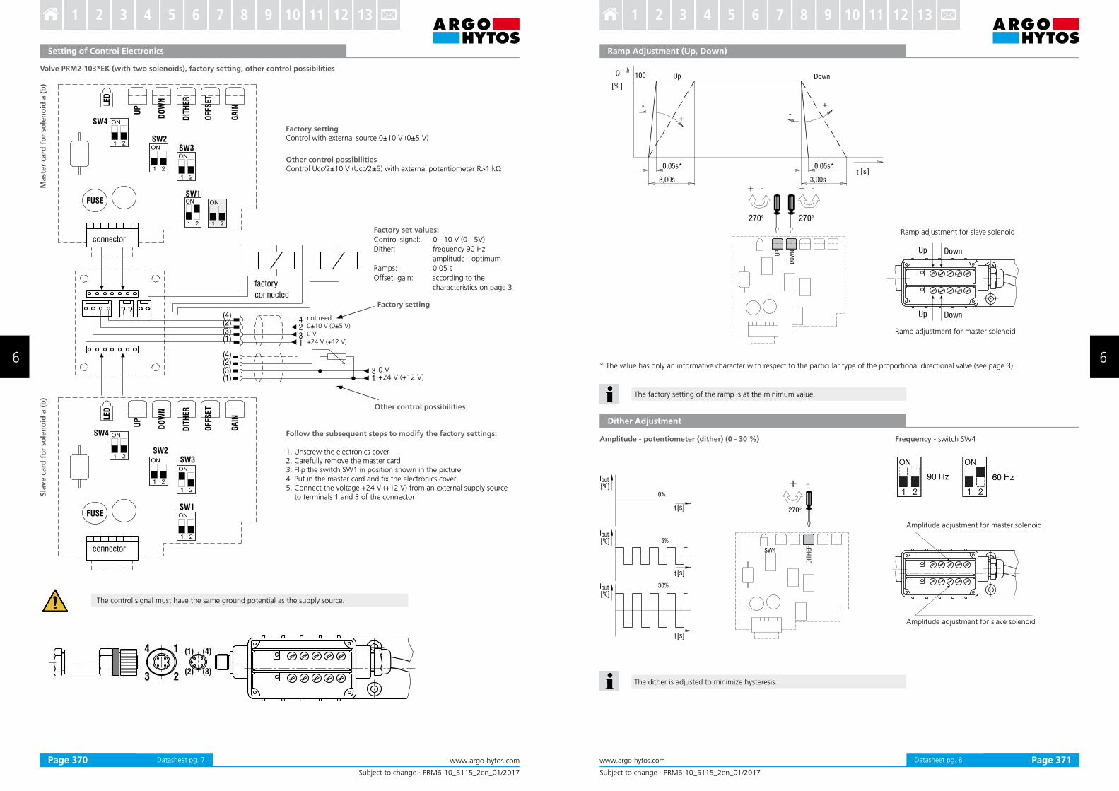
Subject to change · PRM6-10_5115_2en_01/2017
www.argo-hytos.comPage 7
Setting of Control Electronics
Valve PRM2-103*EK (with two solenoids), factory setting, other control possibilities
not used0±10 V (0±5 V)0 V+24 V (+12 V)
Sla
ve c
ard
fo
r so
len
oid
a (
b)
Mast
er
card
fo
r so
len
oid
a (
b)
The control signal must have the same ground potential as the supply source.
Other control possibilitiesControl Ucc/2±10 V (Ucc/2±5) with external potentiometer R>1 kW
Factory settingControl with external source 0±10 V (0±5 V)
Factory set values:
Control signal: 0 - 10 V (0 - 5V)
Dither: frequency 90 Hz
amplitude - optimum
Ramps: 0.05 s
Offset, gain: according to the
characteristics on page 3
Factory setting
0 V+24 V (+12 V)
Follow the subsequent steps to modify the factory settings:
1. Unscrew the electronics cover2. Carefully remove the master card3. Flip the switch SW1 in position shown in the picture4. Put in the master card and ix the electronics cover5. Connect the voltage +24 V (+12 V) from an external supply source
to terminals 1 and 3 of the connector
Other control possibilities
Datasheet pg. 7
Subject to change · PRM6-10_5115_2en_01/2017
www.argo-hytos.com Page 8
Ramp Adjustment (Up, Down)
* The value has only an informative character with respect to the particular type of the proportional directional valve (see page 3).
Dither Adjustment
Amplitude - potentiometer (dither) (0 - 30 %)
Amplitude adjustment for master solenoid
Amplitude adjustment for slave solenoid
Frequency - switch SW4
The factory setting of the ramp is at the minimum value.
The dither is adjusted to minimize hysteresis.
Ramp adjustment for slave solenoid
Ramp adjustment for master solenoid
Datasheet pg. 8Page 370 Page 371
6 6
3 4 5 6 7 8 9 10 11 12 131 2 3 4 5 6 7 8 9 10 11 12 131 2
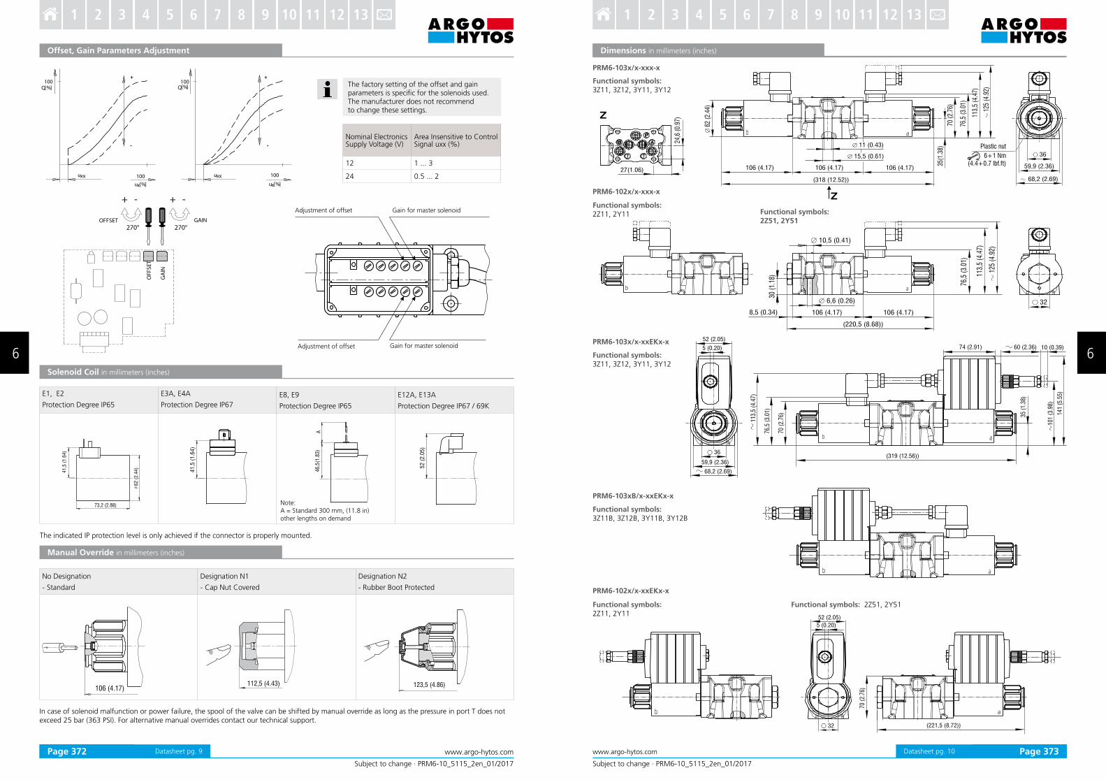
Q[ ]%
ux %[ ] ux %[ ]
uxx uxx100 100
100
Q[ ]%100
+ +
- -O
FF
SE
T
270°
+ -
270°
+ -
GA
IN
OFFSET GAIN
106 (4.17)112,5 (4.43) 123,5 (4.86)
73,2 (2.88)
62
(2
.44
)
41
,5 (
1.6
4)
41,5
(1.6
4)
46
,5(1
.83
)A
52 (
2.0
5)
Subject to change · PRM6-10_5115_2en_01/2017
www.argo-hytos.comPage 9
Offset, Gain Parameters Adjustment
Solenoid Coil in millimeters (inches)
The factory setting of the offset and gain parameters is speciic for the solenoids used.The manufacturer does not recommend to change these settings.
In case of solenoid malfunction or power failure, the spool of the valve can be shifted by manual override as long as the pressure in port T does not exceed 25 bar (363 PSI). For alternative manual overrides contact our technical support.
Adjustment of offset Gain for master solenoid
Adjustment of offset Gain for master solenoid
Note:A = Standard 300 mm, (11.8 in) other lengths on demand
The indicated IP protection level is only achieved if the connector is properly mounted.
Manual Override in millimeters (inches)
Nominal Electronics Supply Voltage (V)
Area Insensitive to Control Signal uxx (%)
12 1 ... 3
24 0.5 ... 2
No Designation
- Standard
Designation N1
- Cap Nut Covered
Designation N2
- Rubber Boot Protected
E1, E2 Protection Degree IP65
E3A, E4A
Protection Degree IP67
E8, E9
Protection Degree IP65
E12A, E13A
Protection Degree IP67 / 69K
Datasheet pg. 9
Subject to change · PRM6-10_5115_2en_01/2017
www.argo-hytos.com Page 10
Dimensions in millimeters (inches)Dimensions in millimeters (inches)
Functional symbols:2Z11, 2Y11
Functional symbols: 2Z51, 2Y51Functional symbols:2Z11, 2Y11
PRM6-103x/x-xxEKx-x
Functional symbols:3Z11, 3Z12, 3Y11, 3Y12
PRM6-103xB/x-xxEKx-x
Functional symbols:3Z11B, 3Z12B, 3Y11B, 3Y12B
PRM6-102x/x-xxx-x
Functional symbols:2Z51, 2Y51
PRM6-103x/x-xxx-x
Functional symbols:3Z11, 3Z12, 3Y11, 3Y12
PRM6-102x/x-xxEKx-x
Plastic nut
6+1 Nm(4.4+0.7 lbf.ft)
Datasheet pg. 10Page 372 Page 373
6 6
3 4 5 6 7 8 9 10 11 12 131 2 3 4 5 6 7 8 9 10 11 12 131 2
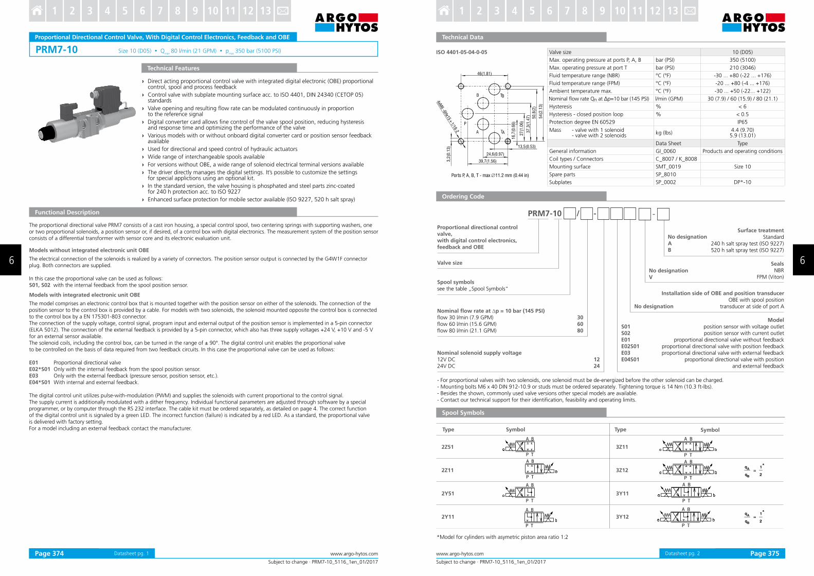
PRM7-10 Size 10 (D05) Qmax 80 l/min (21 GPM) p
max 350 bar (5100 PSI)
Subject to change · PRM7-10_5116_1en_01/2017
www.argo-hytos.comPage 1 Datasheet pg. 1
Proportional Directional Control Valve, With Digital Control Electronics, Feedback and OBE
Technical Features
› Direct acting proportional control valve with integrated digital electronic (OBE) proportional control, spool and process feedback
› Control valve with subplate mounting surface acc. to ISO 4401, DIN 24340 (CETOP 05)standards
› Valve opening and resulting low rate can be modulated continuously in proportion to the reference signal
› Digital converter card allows ine control of the valve spool position, reducing hysteresis and response time and optimizing the performance of the valve
› Various models with or without onboard digital converter card or position sensor feedback available
› Used for directional and speed control of hydraulic actuators
› Wide range of interchangeable spools available
› For versions without OBE, a wide range of solenoid electrical terminal versions available
› The driver directly manages the digital settings. It’s possible to customize the settings for special applictions using an optional kit.
› In the standard version, the valve housing is phosphated and steel parts zinc-coated for 240 h protection acc. to ISO 9227
› Enhanced surface protection for mobile sector available (ISO 9227, 520 h salt spray)
The proportional directional valve PRM7 consists of a cast iron housing, a special control spool, two centering springs with supporting washers, one or two proportional solenoids, a position sensor or, if desired, of a control box with digital electronics. The measurement system of the position sensor consists of a differential transformer with sensor core and its electronic evaluation unit.
Models without integrated electronic unit OBE
The electrical connection of the solenoids is realized by a variety of connectors. The position sensor output is connected by the G4W1F connector plug. Both connectors are supplied.
In this case the proportional valve can be used as follows:S01, S02 with the internal feedback from the spool position sensor.
Models with integrated electronic unit OBE
The model comprises an electronic control box that is mounted together with the position sensor on either of the solenoids. The connection of the position sensor to the control box is provided by a cable. For models with two solenoids, the solenoid mounted opposite the control box is connected to the control box by a EN 175301-803 connector. The connection of the supply voltage, control signal, program input and external output of the position sensor is implemented in a 5-pin connector (ELKA 5012). The connection of the external feedback is provided by a 5-pin connector, which also has three supply voltages +24 V, +10 V and -5 V for an external sensor available. The solenoid coils, including the control box, can be turned in the range of ± 90°. The digital control unit enables the proportional valve to be controlled on the basis of data required from two feedback circuits. In this case the proportional valve can be used as follows:
E01 Proportional directional valveE02*S01 Only with the internal feedback from the spool position sensor.E03 Only with the external feedback (pressure sensor, position sensor, etc.).E04*S01 With internal and external feedback.
The digital control unit utilizes pulse-with-modulation (PWM) and supplies the solenoids with current proportional to the control signal.The supply current is additionally modulated with a dither frequency. Individual functional parameters are adjusted through software by a special programmer, or by computer through the RS 232 interface. The cable kit must be ordered separately, as detailed on page 4. The correct functionof the digital control unit is signaled by a green LED. The incorrect function (failure) is indicated by a red LED. As a standard, the proportional valveis delivered with factory setting. For a model including an external feedback contact the manufacturer.
Functional Description
Subject to change · PRM7-10_5116_1en_01/2017
www.argo-hytos.com Page 2Datasheet pg. 2
13,5(0.53)
24,6(0.97)
39,7(1.56)
46(1.81)
16
,7(0
.66
)
27
(1.0
6)
37
,3(1
.47
)
50
,8(2
)
54
(2.1
3)
3,2
(0.1
3)
4xM6 -6H
x15+1/18-2 TAA
B
P
TB
ISO 4401-05-04-0-05
- For proportional valves with two solenoids, one solenoid must be de-energized before the other solenoid can be charged.- Mounting bolts M6 x 40 DIN 912-10.9 or studs must be ordered separately. Tightening torque is 14 Nm (10.3 ft-lbs).- Besides the shown, commonly used valve versions other special models are available.- Contact our technical support for their identiication, feasibility and operating limits.
PRM7-10 / -
Spool symbolssee the table „Spool Symbols“
Valve size
No designationAB
Surface treatmentStandard
240 h salt spray test (ISO 9227)520 h salt spray test (ISO 9227)
1224
No designationV
Nominal solenoid supply voltage12V DC24V DC
SealsNBR
FPM (Viton)
Modelposition sensor with voltage outlet position sensor with current outlet
proportional directional valve without feedbackproportional directional valve with position feedbackproportional directional valve with external feedback
proportional directional valve with positionand external feedback
S01S02E01E02S01E03E04S01
Proportional directional controlvalve, with digital control electronics, feedback and OBE
Nominal low rate at Dp = 10 bar (145 PSI)low 30 l/min (7.9 GPM)low 60 l/min (15.6 GPM)low 80 l/min (21.1 GPM)
306080
No designation
Installation side of OBE and position transducerOBE with spool position
transducer at side of port A
Ports P, A, B, T - max ∅11.2 mm (0.44 in)
Spool Symbols
q
q=
1
2
*A
B
q
q=
1
2
*A
B
*Model for cylinders with asymetric piston area ratio 1:2
Type Symbol Type Symbol
2Z51 3Z11
2Z11 3Z12
2Y51 3Y11
2Y11 3Y12
Valve size 10 (D05)
Max. operating pressure at ports P, A, B bar (PSI) 350 (5100)
Max. operating pressure at port T bar (PSI) 210 (3046)
Fluid temperature range (NBR) °C (°F) -30 ... +80 (-22 ... +176)
Fluid temperature range (FPM) °C (°F) -20 ... +80 (-4 ... +176)
Ambient temperature max. °C (°F) -30 ... +50 (-22... +122)
Nominal low rate Qn at ∆p=10 bar (145 PSI) l/min (GPM) 30 (7.9) / 60 (15.9) / 80 (21.1)
Hysteresis % < 6
Hysteresis - closed position loop % < 0.5
Protection degree EN 60529 IP65
Mass - valve with 1 solenoid - valve with 2 solenoids
kg (Ibs)4.4 (9.70)5.9 (13.01)
Data Sheet Type
General information GI_0060 Products and operating conditions
Coil types / Connectors C_8007 / K_8008
Mounting surface SMT_0019 Size 10
Spare parts SP_8010
Subplates SP_0002 DP*-10
Technical Data
Ordering Code
Page 374 Page 375
6 6
3 4 5 6 7 8 9 10 11 12 131 2 3 4 5 6 7 8 9 10 11 12 131 2
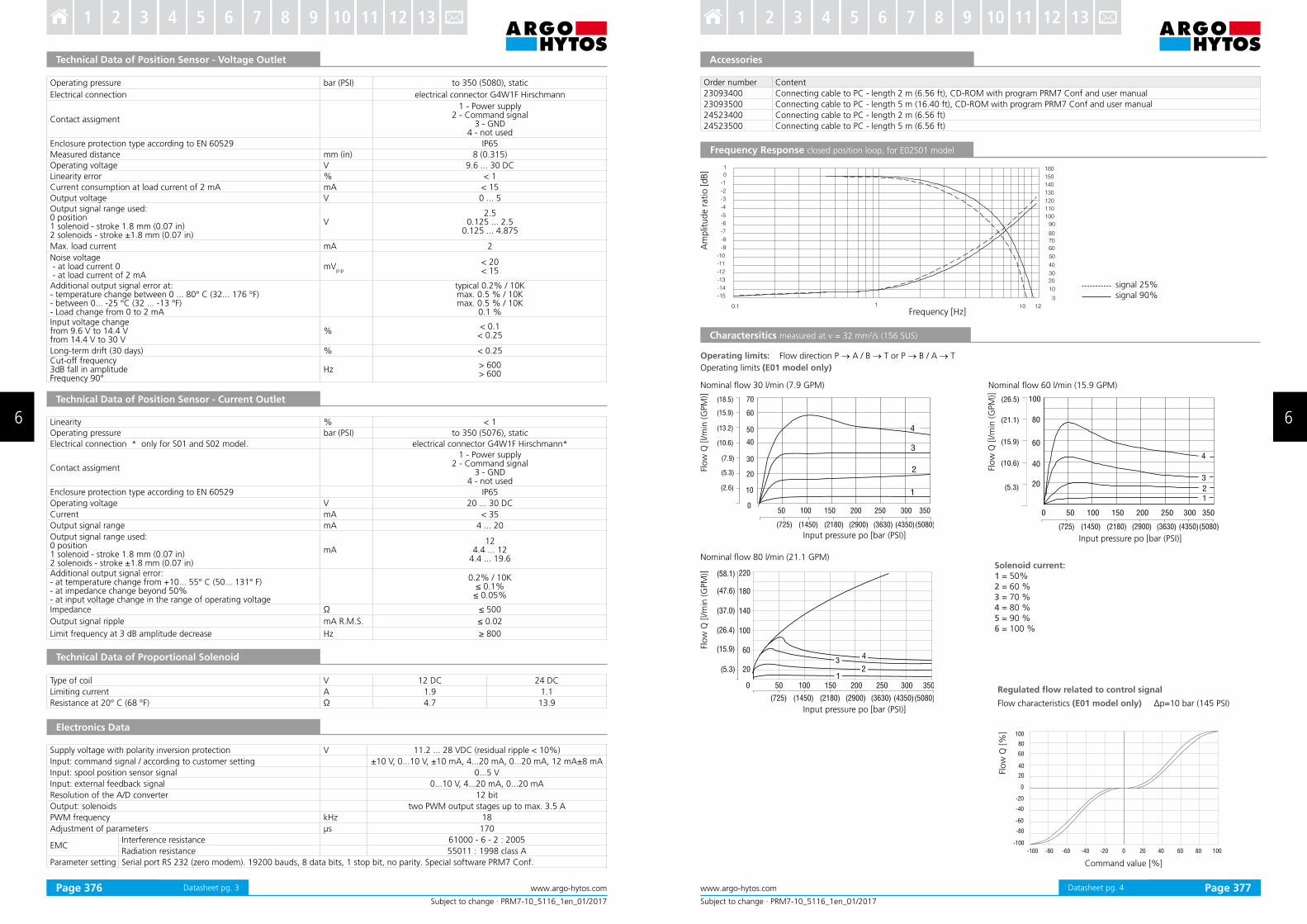
Subject to change · PRM7-10_5116_1en_01/2017
www.argo-hytos.comPage 3 Datasheet pg. 3
Technical Data of Position Sensor - Voltage Outlet
Operating pressure bar (PSI) to 350 (5080), static
Electrical connection electrical connector G4W1F Hirschmann
Contact assigment
1 - Power supply2 - Command signal
3 - GND4 - not used
Enclosure protection type according to EN 60529 IP65
Measured distance mm (in) 8 (0.315)
Operating voltage V 9.6 ... 30 DC
Linearity error % < 1
Current consumption at load current of 2 mA mA < 15
Output voltage V 0 ... 5Output signal range used:0 position1 solenoid - stroke 1.8 mm (0.07 in)2 solenoids - stroke ±1.8 mm (0.07 in)
V2.5
0.125 ... 2.50.125 ... 4.875
Max. load current mA 2
Noise voltage - at load current 0 - at load current of 2 mA
mVp-p
< 20< 15
Additional output signal error at:- temperature change between 0 ... 80° C (32... 176 °F)- between 0... -25 °C (32 ... -13 °F)- Load change from 0 to 2 mA
typical 0.2% / 10Kmax. 0.5 % / 10Kmax. 0.5 % / 10K
0.1 %Input voltage changefrom 9.6 V to 14.4 Vfrom 14.4 V to 30 V
%< 0.1
< 0.25
Long-term drift (30 days) % < 0.25Cut-off frequency3dB fall in amplitudeFrequency 90°
Hz> 600> 600
Technical Data of Position Sensor - Current Outlet
Linearity % < 1
Operating pressure bar (PSI) to 350 (5076), static
Electrical connection * only for S01 and S02 model. electrical connector G4W1F Hirschmann*
Contact assigment
1 - Power supply2 - Command signal
3 - GND4 - not used
Enclosure protection type according to EN 60529 IP65
Operating voltage V 20 ... 30 DC
Current mA < 35
Output signal range mA 4 ... 20
Output signal range used:0 position1 solenoid - stroke 1.8 mm (0.07 in)2 solenoids - stroke ±1.8 mm (0.07 in)
mA12
4.4 ... 124.4 ... 19.6
Additional output signal error:- at temperature change from +10... 55° C (50... 131° F)- at impedance change beyond 50%- at input voltage change in the range of operating voltage
0.2% / 10K≤ 0.1%≤ 0.05%
Impedance Ω ≤ 500
Output signal ripple mA R.M.S. ≤ 0.02
Limit frequency at 3 dB amplitude decrease Hz ≥ 800
Technical Data of Proportional Solenoid
Type of coil V 12 DC 24 DC
Limiting current A 1.9 1.1
Resistance at 20° C (68 °F) Ω 4.7 13.9
Electronics Data
Supply voltage with polarity inversion protection V 11.2 ... 28 VDC (residual ripple < 10%)
Input: command signal / according to customer setting ±10 V, 0...10 V, ±10 mA, 4...20 mA, 0...20 mA, 12 mA±8 mA
Input: spool position sensor signal 0...5 V
Input: external feedback signal 0...10 V, 4...20 mA, 0...20 mA
Resolution of the A/D converter 12 bit
Output: solenoids two PWM output stages up to max. 3.5 A
PWM frequency kHz 18
Adjustment of parameters μs 170
EMCInterference resistance 61000 - 6 - 2 : 2005
Radiation resistance 55011 : 1998 class A
Parameter setting Serial port RS 232 (zero modem). 19200 bauds, 8 data bits, 1 stop bit, no parity. Special software PRM7 Conf.
Subject to change · PRM7-10_5116_1en_01/2017
www.argo-hytos.com Page 4Datasheet pg. 4
Order number Content
23093400 Connecting cable to PC - length 2 m (6.56 ft), CD-ROM with program PRM7 Conf and user manual
23093500 Connecting cable to PC - length 5 m (16.40 ft), CD-ROM with program PRM7 Conf and user manual
24523400 Connecting cable to PC - length 2 m (6.56 ft)
24523500 Connecting cable to PC - length 5 m (6.56 ft)
Accessories
Frequency Response closed position loop, for E02S01 model
Am
plit
ude r
atio [dB]
Nominal low 30 l/min (7.9 GPM) Nominal low 60 l/min (15.9 GPM)
Operating limits: Flow direction P → A / B → T or P → B / A → T
Operating limits (E01 model only)
Input pressure po [bar (PSI)]Input pressure po [bar (PSI)]
Input pressure po [bar (PSI)]
Flow
Q [l/m
in (G
PM
)]
Charactersitics measured at ν = 32 mm2/s (156 SUS)
Flow
Q [l/m
in (G
PM
)]
Frequency [Hz]
Nominal low 80 l/min (21.1 GPM)
Flo
w Q
[l/m
in (G
PM
)]
Solenoid current:1 = 50% 2 = 60 % 3 = 70 % 4 = 80 % 5 = 90 % 6 = 100 %
Flow
Q [%
]
Command value [%]
signal 25%signal 90%
Regulated low related to control signal
Flow characteristics (E01 model only) Δp=10 bar (145 PSI)
Page 376 Page 377
6 6
3 4 5 6 7 8 9 10 11 12 131 2 3 4 5 6 7 8 9 10 11 12 131 2

Subject to change · PRM7-10_5116_1en_01/2017
www.argo-hytos.comPage 5 Datasheet pg. 5
Flow Characteristics measured at ν = 32 mm2/s (156 SUS)
(21.1)
(15.9)
(10.6)
(5.3)
0 0
(-5.3)
(-10.6)
(-15.9)
(-21.1)
80
60
40
20
-20
-40
-60
-80
0-20-40-60-80 80604020-100 100
Flow
Q [l/m
in (G
PM
)]
Flow
Q [l/m
in (G
PM
)]
Qn = 60 l/min (15.9 GPM) by Dp = 10 bar (145 PSI)Q
n = 30 l/min (7.9 GPM) by Dp = 10 bar (145 PSI)
Flow
Q [l/m
in (G
PM
)]
Command value [%]
Qn = 80 l/min (21.1 GPM) by Dp = 10 bar (145 PSI)
Command value [%] Command value [%]
Dp = Valve pressure differential (inlet pressure pV minus load pressure
and return pressure pT)
Dpn = Valve pressure differential for nominal low Q
n)
1 Dpn = 10 bar (145 PSI)
2 Dp = 50 bar (725 PSI)
3 Dp = 160 bar (2321 PSI)
4 Dp = 320 bar (4641 PSI)
Flow characteristics (E02S01 model only)
Connector K2 - type M12x1 (male)
PIN Technical data
1 TxD
2 RxD
3 Ground (signal)
4 Not used
4
21
5 3
K3 Connector K3 - type M12x1 (female)
PIN Technical data
1 Power supply output
2 Signal of external feedback
3 Ground
4 Not used
5 Not used
K3
3
12
4
K2K2
K1 Connector K1 - type M23 (male)
PIN Technical data
1 * Power supply input
2 * Ground (power supply)
3 Control signal
4 Ground (signal)
5 Power reference signal
6 Control signal of position sensor spool
7 * Protective earth lead (PE)
*Recommended min. lead cross section 0.75 mm2
a b
K2 - Connection RS232 M12x1 (4 PIN) To program the electronics
K1 - Main input connector M23 (7 PIN)Cable diameter 8 ...12 mm (0.31...0.47 in)
K3 - Connector M12x1 (5 PIN) External feedback signal (for conigurations
E03 and E04S01 only)
Factory Settings
Connectors
Model
Item E01 E02S01 E03 E04S01
1 Magnet 2 Magnets 1 Magnet 2 Magnets 1 Magnet 2 Magnets 1 Magnet 2 Magnets
Control signal 0 ... 10 V ± 10 V 0 ... 10 V ± 10 V 0 ... 10 V ± 10 V 0 ... 10 V ± 10 V
Signal external feedback - - - 0 ... 10 V
Output position sensor spool - 0 ... 5 V - 0 ... 5 V
PRM7-102, 103 ... S01
PRM7-102, 103 ... S02
PRM7-102, 103 ... E01 - without connector plug for spool position feedback
PRM7-102, 103 ... E03
PRM7-1023 ... E02S01 - without connector plug for spool position feedback
PRM7-103 ... E04S01
1 Solenoid a2 Solenoid b3 Manual override4 Name plate5 4 mounting holes6 Solenoid ixing nut7 Connector M12x1 for connection
of external feedback8 Main supply connector M239 Square ring 7.65 x 1.68 (4 pcs.),
supplied in delivery packet10 Cover of connector M12x1 for programming11 Plastic box with integrated
electronics12 Position sensor
10
7
8
4
12 11 1 5 9 2 6 3
Subject to change · PRM7-10_5116_1en_01/2017
www.argo-hytos.com Page 6Datasheet pg. 6
Dimensions in millimeters (inches)
Page 378 Page 379
6 6
3 4 5 6 7 8 9 10 11 12 131 2 3 4 5 6 7 8 9 10 11 12 131 2

PRM8-06 Size 06 (D03) Qmax
140 l/min (37 GPM) • pmax
350 bar (5100 PSI)
T P
B
A
G
0,75 (0.03)
4xM5-6Hx13
15,5 (0.61)
31,75 (1.25)
5,1 (0.20)
25,9 (1.16)
31 (1.22)
12
,7 (
0.5
0)
21
,5 (
0.8
5)
30
,2 (
1.1
8)
40
,5 (
1.5
9)
ISO 4401-03-02-0-05
Subject to change · PRM8-06_5178_1en_01/2017
www.argo-hytos.comPage 1 Datasheet pg” 1
Proportional Directional Control Valve, Pilot Operated
› Pilot operated proportional control valve with exceptional hydraulic power limits
› Subplate mounting surface acc” to ISO 4401’ DIN 24340 (CETOP 03) standards
› The valve opening and resulting low rate can be modulated continuously in proportion to the reference signal
› The valve can be controlled directly by a current control supply unit or by a electronic control unit to exploit the valve performance to the fullest
› Analog converter card EL6 allows ine position control of the valve spool’ reducing hysteresis and response time and optimizing the performance of the valve
› Five chamber housing design with reduced hydraulic power dependence on luid viscosity
› Wide range of electrical terminal versions for the solenoids available
› Wide range of interchangeable spools and manual overrides available
› The coil is fastened to the core tube with a retaining nut and can be rotated by 360° to suit the available space
› In the standard version’ the valve housing is phosphated and steel parts zinc“coated for 240 h salt spray protection acc” to ISO 9227
› Enhanced surface protection for mobile sector available (ISO 9227’ 520 h salt spray)
Technical Features
Functional Description
The pilot operated main spool valve follows the control spool position’ which is given by the control current to the solenoid” The solenoids are supplied from an external source’ which should be provided with a current feedback” In order to achieve optimum operating parameters the external electronics should be able to generate a dither signal” The proportional valve can be used within the whole range of input pressure where the required continuity of the low rate characteristics and minimum hysteresis is achieved” The selected concept increases the achieved output parameters of the proportional valve in comparison to direct controlled proportional valve” The valve can be controlled directly by a current control supply unit or by means of the external electronic card directly mounted to the electricalterminal (see Catalogue of EL3E card 9145 and EL6 card 9150)” This control card’ depending on the number of the controlled solenoids’ can be mounted onto either solenoid”
Technical Data
Valve size 06 (D03)Max” operating pressure at ports P’ A’ B bar (PSI) 350 (5080)Maximal low at pressure 320 bar (4640 PSI) l/min (GPM) 140 (37)Maximum operating pressure at port T bar (PSI) 210 (3050)Fluid temperature range (NBR / (FPM) °C (°F) “30 ”” ‘80 (“22 ””” ‘176) / “20 ”” ‘80 (“4 ”” ‘176)Ambient temperature max” °C (°F) “30 ””” ‘50 (“22 ””” ‘122)Nominal low rate Qn at Δp=10 bar (145 PSI) l/min (GPM) 25 (6”6)Hysteresis % < 6Service life cycles 106
Mass kg (Ibs) 2”4 (5”3)Technical data of the proportional solenoidNominal supply voltage V 12 DC 24 DCLimit current A 2”5 1”0Mean resistance value at 20 °C (68 °F) W 2”3 13”4
Data Sheet TypeGeneral information GI_0060 Products and operating conditionsCoil types / Connectors C_8007 C22B* / K*Mounting surface SMT_0019 Size 06Spare parts SP_8010
Characteristics measured at ν = 32 mm2/s (156 SUS)
Operating limits: Flow direction P → A / B → T or P → B / A → T
The coil current initializing the low through the proportional directional valvecan differ due to the production tolerances in a range of ± 6% of the limit current”
Flow
Q [
l/m
in (
GPM
)]
Control current Ic [%]Input pressure pin [bar (PSI)]
Flow
Q [
l/m
in (
GPM
)]
Regulated low related to control signal Δp=10 bar (145 PSI)
Ports P, A, B, T - max ∅7.5 mm (0.29 in)
Subject to change · PRM8-06_5178_1en_01/2017
www.argo-hytos.com Page 2Datasheet pg” 2
Valve size
Surface treatmentstandard
zinc“coated (ZnCr“3)’ ISO 9227 (240 h) zinc“coated (ZnNi)’ ISO 9227 (520 h)
1224
Rated supply voltage of solenoids (at the coil terminal)12 V DC24 V DC
Manual overridestandard
protected with retaining nutprotected with rubber boot
No designationN1N2
Connectorwith terminal for the connector’ EN 175301“803“A
E1 with quenching diodewith AMP“Junior“Timer“connector “ Axial direction
E3A with quenching diodeloose conductors (two insulated wires)
E8 with quenching diodewith Deutsch DT04“2P
E12A with quenching diode
E1E2E3AE4AE8E9E12AE13A
PRM8-06 / -
SealsNBR
FPM (Viton)
No designationV
Spool symbols
25
3Z11
3Y11
-
Ordering Code
Proportional directional control valve No designationAB
Nominal low rate at ∆p = 10 bar (145 PSI)25 l/min (6”6 GPM)
Solenoid Coil in millimeters (inches)
In case of solenoid malfunction or power failure’ the spool of the valve can be shifted by manual override as long as the pressure in port T does not exceed 25 bar (363 PSI)” For alternative manual overrides contact our technical support”
45
77
)(1
.
32
,5(1
.27
)
52 (2.05)
41
,1 (
1.6
2)
32
,5(1
.28
)A
46
,3 (
1.8
2)
Note:A = Standard 300 mm’ (11”8 in) other lengths on demand
No Designation“ Standard
Designation N1“ Cap Nut Covered
Designation N2“ Rubber Boot Protected
Manual Override in millimeters (inches)
a
73 (2.87) 79,5 (3.13)
a
85 (3.35)
a
E1’ E2 Protection degree IP65
E3A’ E4AProtection degree IP67
E8’ E9Protection degree IP65
E12A’ E13AProtection degree IP67 / 69K
The indicated IPprotection level is only achieved if the connector is properly mounted”
“ For proportional valves with two solenoids’ one solenoid must be de“energized before the other solenoid can be charged”“ The solenoid operated valves are delivered without connectors” For available connectors see data sheet K_8008”“ Electronics for controlling proportional valves can be ordered separately’ see catalog HA 9150”“ Mounting bolts M5 x 45 DIN 912“10”9 or studs must be ordered separately” Tightening torque is 8”9 Nm (6”56 ft“Ibf)“ Besides the shown widely used valve versions other special models are available” Contact our technical support for their identiication’ feasibility and operating limits”
Dimensions in millimeters (inches)
Plastic nut3+1 Nm
(2.2+0.7 ft-lbf)
Proper function of the valve is guaranteed only if the supply pressure in the P channel is present and exceeds always the pressure in the T channel”
Page 380 Page 381
6 6
3 4 5 6 7 8 9 10 11 12 131 2 3 4 5 6 7 8 9 10 11 12 131 2
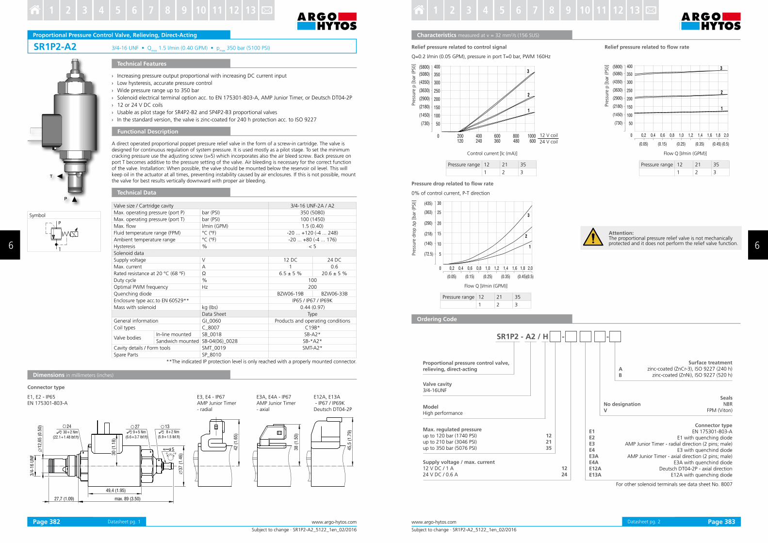
SR1P2-A2 3/4“16 UNF • Qmax
1”5 l/min (0”40 GPM) • pmax
350 bar (5100 PSI)
38
(1
.50
)
45
,5 (
1.7
9)
42
(1
.65
)
49,4 (1.95)
27,7 (1.09) max. 89 (3.50)
3/4
-16
UN
F
12
,65
(0
.50
) 24 1327
37
(1
.46
)
30+2 Nm
(22.1+1.48 lbf.ft)
30
(1
.18
)
8+2 Nm
(5.9+1.5 lbf.ft)
9+5 Nm
(6.6+3.7 lbf.ft)
5+pp
Symbol
Subject to change · SR1P2-A2_5122_1en_02/2016
www.argo-hytos.comPage 1
Proportional Pressure Control Valve, Relieving, Direct-Acting
Technical Features
› Increasing pressure output proportional with increasing DC current input
› Low hysteresis’ accurate pressure control
› Wide pressure range up to 350 bar
› Solenoid electrical terminal option acc” to EN 175301“803“A’ AMP Junior Timer’ or Deutsch DT04“2P
› 12 or 24 V DC coils
› Usable as pilot stage for SR4P2“B2 and SP4P2“B3 proportional valves
› In the standard version’ the valve is zinc“coated for 240 h protection acc” to ISO 9227
Functional Description
Technical Data
A direct operated proportional poppet pressure relief valve in the form of a screw“in cartridge” The valve is designed for continuous regulation of system pressure” It is used mostly as a pilot stage” To set the minimum cracking pressure use the adjusting screw (s=5) which incorporates also the air bleed screw” Back pressure on port T becomes additive to the pressure setting of the valve” Air bleeding is necessary for the correct function of the valve” Installation: When possible’ the valve should be mounted below the reservoir oil level” This will keep oil in the actuator at all times’ preventing instability caused by air enclosures” If this is not possible’ mount the valve for best results vertically downward with proper air bleeding”
Valve size / Cartridge cavity 3/4“16 UNF“2A / A2
Max” operating pressure (port P) bar (PSI) 350 (5080)
Max” operating pressure (port T) bar (PSI) 100 (1450)
Max” low l/min (GPM) 1.5 (0.40)
Fluid temperature range (FPM) °C (°F) “20 ””” ‘120 (“4 ””” 248)
Ambient temperature range °C (°F) “20 ””” ‘80 (“4 ””” 176)
Hysteresis % < 5
Solenoid data
Supply voltage V 12 DC 24 DC
Max” current A 1 0.6
Rated resistance at 20 °C (68 °F) Ω 6.5 ± 5 % 20”6 ± 5 %
Duty cycle % 100
Optimal PWM frequency Hz 200
Quenching diode BZW06“19B BZW06“33B
Enclosure type acc”to EN 60529** IP65 / IP67 / IP69K
Mass with solenoid kg (Ibs) 0”44 (0”97)
Data Sheet Type
General information GI_0060 Products and operating conditions
Coil types C_8007 C19B*
Valve bodiesIn“line mounted SB_0018 SB“A2*
Sandwich mounted SB“04(06)_0028 SB“*A2*
Cavity details / Form tools SMT_0019 SMT“A2*
Spare Parts SP_8010
**The indicated IP protection level is only reached with a properly mounted connector”
Dimensions in millimeters (inches)
Connector type
E1’ E2 “ IP65EN 175301“803“A
E3A’ E4A “ IP67AMP Junior Timer - axial
E12A’ E13A “ IP67 / IP69K Deutsch DT04“2P
E3’ E4 “ IP67AMP Junior Timer - radial
Datasheet pg” 1
SR1P2 - A2 / H - -
0
2 05
300
1 00
200
50( 30)7
400
350
(2900)
(3630)
(4350)
(5080)
(5800)
400 600 800 1000120 240 600360 480
3
2
11 05
200
(1450)
(2180)
250
300
1 00
50( 30)7
400
350
(2900)
(3630)
(4350)
(5080)
(5800) 3
2
11 05
200
(1450)
(2180)
0 0,2 0,4 0,6 0,8 1,0 1,2 1,4 1,6 1,8 2,0
(0.05) (0.15) (0.25) (0.35) (0.45) (0.5)
0
15
20
10
0,2
5( . )72 5
30
25
( )140
( )218
( )290
( )363
( )435
3
2
0,4 0,6 0,8 1,0 1,2 1,4 1,6 1,8 2,0
( .05)0 (0.15) (0.25) (0.35) (0.45)(0.5)
1
AB
122135
1224
E1E2E3E4E3AE4AE12AE13A
Subject to change · SR1P2-A2_5122_1en_02/2016
www.argo-hytos.com Page 2
Characteristics measured at ν = 32 mm2/s (156 SUS)
Ordering Code
Proportional pressure control valve,relieving, direct-acting
Max. regulated pressureup to 120 bar (1740 PSI)up to 210 bar (3046 PSI)up to 350 bar (5076 PSI)
Surface treatmentzinc“coated (ZnCr“3)’ ISO 9227 (240 h)
zinc“coated (ZnNi)’ ISO 9227 (520 h)
No designationV
SealsNBR
FPM (Viton)
Supply voltage / max. current12 V DC / 1 A24 V DC / 0”6 A
Connector typeEN 175301“803“A
E1 with quenching diodeAMP Junior Timer “ radial direction (2 pins; male)
E3 with quenchind diodeAMP Junior Timer “ axial direction (2 pins; male)
E3A with quenchind diodeDeutsch DT04“2P “ axial direction
E12A with quenching diode
ModelHigh performance
For other solenoid terminals see data sheet No” 8007
Pressure drop related to low rate
Pre
ssu
re d
rop
∆p
[b
ar
(PSI)]
Flow Q [I/min (GPM)]
0% of control current’ P“T direction
Relief pressure related to control signal
Pre
ssure
p [
bar
(PSI)]
Control current [Ic (mA)]
12 V coil
24 V coil
Relief pressure related to low rate
Pre
ssure
p [
bar
(PSI)]
Flow Q [I/min (GPM)]
Q=0”2 l/min (0”05 GPM)’ pressure in port T=0 bar’ PWM 160Hz
Valve cavity3/4-16UNF
Pressure range 12 21 35
1 2 3
Pressure range 12 21 35
1 2 3
Pressure range 12 21 35
1 2 3
Attention: The proportional pressure relief valve is not mechanically protected and it does not perform the relief valve function”
Datasheet pg” 2Page 382 Page 383
6 6
3 4 5 6 7 8 9 10 11 12 131 2 3 4 5 6 7 8 9 10 11 12 131 2

SRN1P1-A2 3/4“16 UNF • Qmax
1”5 l/min (0”40 GPM) • pmax
350 bar (5100 PSI)
38
(1
.50
)
45
,5 (
1.7
9)
49,4 (1.95)
max. 97 (3.83)27,7 (1.09)
3/4
-16
UN
F
12
.65
(0
.5)
37
(1
.46
)
2430+2 Nm
(22.1+1.48 lbf.ft)
30
(1
.18
)
13278+2 Nm
(5.9+1.5 lbf.ft)
9+5 Nm
(6.6+3.7 lbf.ft)
5 42
(1
.65
)
+pp
T
Subject to change · SRN1P1-A2_5137_1en_02/2016
www.argo-hytos.comPage 1
Proportional Pressure Control Valve, Relieving, Direct-Acting, Inverted
Technical Features
› Decreasing pressure output proportional with increasing DC current input
› Low hysteresis’ accurate pressure control
› Wide pressure range up to 350 bar
› Mechanical adjustment of minimum cracking pressure
› Solenoid electrical terminal option acc” to EN 175301“803“A’ AMP Junior Timer or Deutsch DT04“2P
› 12 or 24 V DC coils
› Usable as pilot stage of SRN4P1“B2 and SPN4P1“B3 proportional valves
› In the standard version’ the valve is zinc“coated for 240 h protection acc” to ISO 9227
Functional Description
Technical Data
A direct operated proportional poppet pressure relief valve in the form of a screw“in cartridge” The valve is designed for continuous regulation of system pressure” It is used mostly as a pilot stage” To set the minimum cracking pressure use the adjusting screw (s=5) which incorporates also the air bleed screw” Back pressure on port T becomes additive to the pressure setting of the valve” Air bleeding is necessary for the correct function of the valve” Installation: When possible’ the valve should be mounted below the reservoir oil level” This will keep oil in the actuator at all times’ preventing instability caused by air enclosures” If this is not possible’ mount the valve for best results vertically downward with proper air bleeding”
Dimensions in millimeters (inches)
E1’ E2 “ IP65EN 175301“803“A
E3A’ E4A “ IP67AMP Junior Timer - axial
E12A’ E13A “ IP67 / IP69K Deutsch DT04“2P
Connector type
E3’ E4 “ IP67AMP Junior Timer - radial
Valve size / Cartridge cavity 3/4“16 UNF“2A / A2
Max” operating pressure (port P) bar (PSI) 350 (5080)
Max” operating pressure (port T) bar (PSI) 100 (1450)
Max” low l/min (GPM) 1.5 (0.40)
Fluid temperature range (FPM) °C (°F) “20 ””” ‘120 (“4 ””” 248)
Ambient temperature range °C (°F) “20 ””” ‘80 (“4 ””” 176)
Hysteresis % < 5
Solenoid data
Supply voltage V 12 DC 24 DC
Max” current A 1 0’6
Rated resistance at 20 °C (68 °F) Ω 6.5 ± 5 % 20”6 ± 5 %
Duty cycle % 100
Optimal PWM frequency Hz 160 “ 200
Quenching diode BZW06“19B BZW06“33B
Enclosure type acc”to EN 60529** IP65 / IP67 / IP69K
Mass with solenoid kg (Ibs) 0”44 (0”97)
Data Sheet Type
General information GI_0060 Products and operating conditions
Coil types C_8007 C19B*
Valve bodiesIn“line mounted SB_0018 SB“A2*
Sandwich mounted SB“04(06)_0028 SB“*A2*
Cavity details / Form tools SMT_0019 SMT“A2*
Spare Parts SP_8010
**The indicated IP protection level is reached only with a properly mounted connector”
Symbol
Datasheet pg” 1
A
B
122135
1224
E1E2E3E4E3AE4AE12AE13A
SRN1P1 - A2 / H - -
3
2
1
0
15
20
10
0,2
5( . )72 5
30
25
( )140
( )218
( )290
( )363
( )435
3
2
0,4 0,6 0,8 1,0 1,2 1,4 1,6 1,8 2,0
( .05)0 (0.15) (0.25) (0.35) (0.45)(0.5)
1
1,6 1,8 2,0
(0.48) (0.53)
(1450)
(2175)
(725)
(4350)
(5075)
(29001)
(3625)
0 0,2 0,4 0,6 0,8 1,2
100
150
50
200
250
(0.05) (0.15) (0.37)(0.26)
1,4
400(5800)
1,0
350
300
1
2
45
3
Subject to change · SRN1P1-A2_5137_1en_02/2016
www.argo-hytos.com Page 2
Characteristics measured at ν = 32 mm2/s (156 SUS)
Pre
ssu
re d
rop
∆p
[bar
(PSI)]
Flow Q [l/min (GPM)]
Ordering Code
Proportional pressure control valve,relieving, direct-acting, inverted
Max. regulated pressureup to 120 bar (1740 PSI)up to 210 bar (3046 PSI)up to 350 bar (5076 PSI)
Surface treatmentzinc“coated (ZnCr“3)’ ISO 9227 (240 h)
zinc“coated (ZnNi)’ ISO 9227 (520 h)
No designationV
SealsNBR
FPM (Viton)
Supply voltage / max. current12 V DC / 1 A24 V DC / 0”6 A
Connector typeEN 175301“803“A
E1 with quenching diodeAMP Junior Timer “ radial direction (2 pins; male)
E3 with quenchind diodeAMP Junior Timer “ axial direction (2 pins; male)
E3A with quenchind diodeDeutsch DT04“2P “ axial direction
E12A with quenching diode
ModelHigh performance
For other solenoid terminals see data sheet No” 8007
Valve cavity3/4-16UNF
Control current Ic [mA]
Pre
ssure
p [
bar
(PSI)]
Pressure range 12 21 35
1 2 3
Pre
ssure
p [
bar
(PSI)]
Flow Q [l/min (GPM)]
12 V coil
24 V coil
Relief pressure related to control signal Relief pressure related to low rate
Q=0”2 l/min (0”05 GPM)’ pressure in port T=0 bar’ PWM 160Hz
Pressure drop related to low rate
100% of control current’ P“T direction
Pressure range 35’ various control currents
Controlcurrent
1 2 3 4 5
100 % Imax 75 % Imax 50 % Imax 25 % Imax 0 % Imax
Pressure range 12 21 35
1 2 3
Datasheet pg” 2Page 384 Page 385
6 6
3 4 5 6 7 8 9 10 11 12 131 2 3 4 5 6 7 8 9 10 11 12 131 2
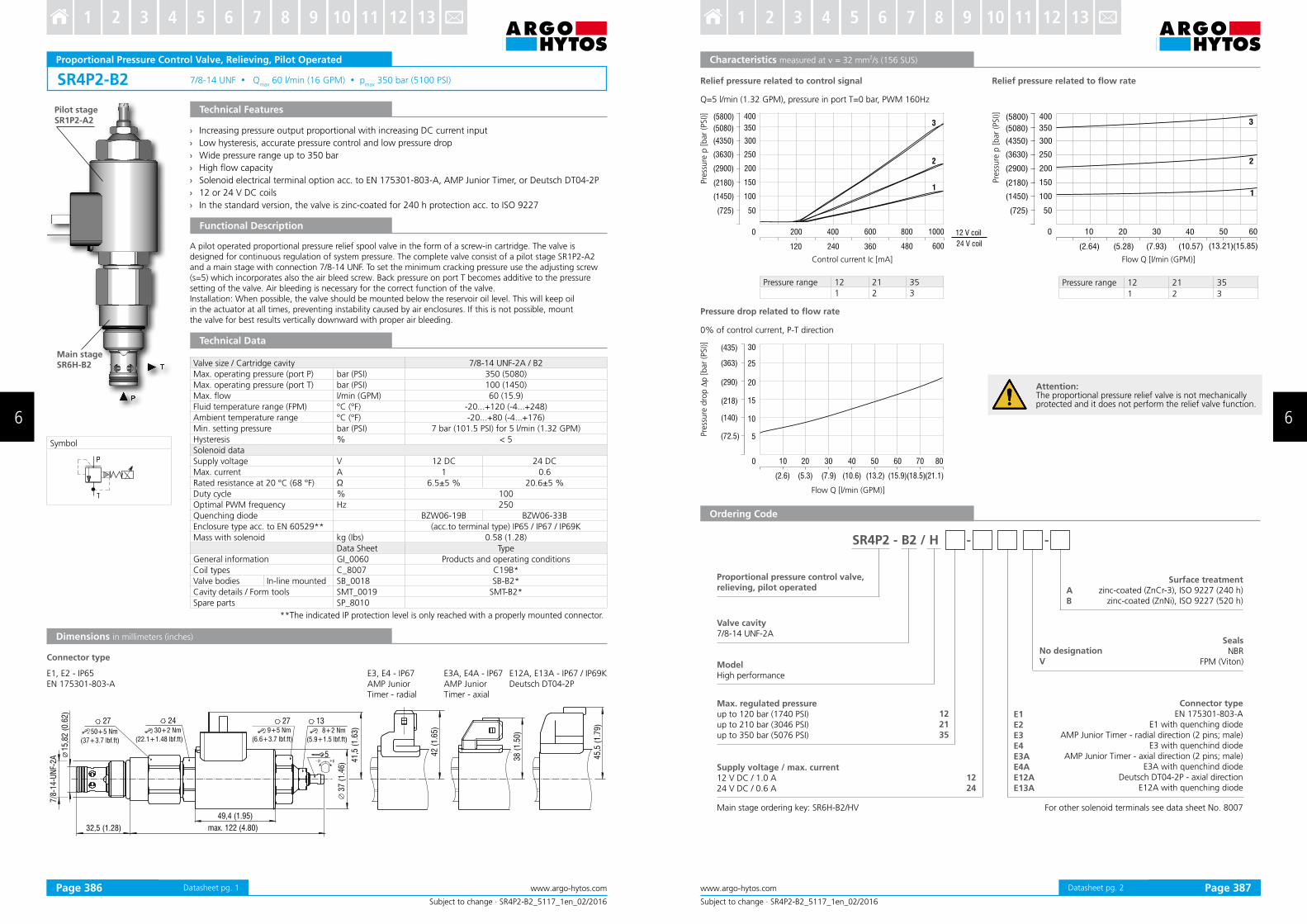
SR4P2-B2 7/8-14 UNF Qmax
60 l/min (16 GPM) pmax
350 bar (5100 PSI)
+pp
Symbol
Subject to change · SR4P2-B2_5117_1en_02/2016
www.argo-hytos.comStrana 1
Proportional Pressure Control Valve, Relieving, Pilot Operated
Technical Features
› Increasing pressure output proportional with increasing DC current input
› Low hysteresis, accurate pressure control and low pressure drop
› Wide pressure range up to 350 bar
› High low capacity
› Solenoid electrical terminal option acc. to EN 175301-803-A, AMP Junior Timer, or Deutsch DT04-2P
› 12 or 24 V DC coils
› In the standard version, the valve is zinc-coated for 240 h protection acc. to ISO 9227
Technical Data
Functional Description
Dimensions in millimeters (inches)
Valve size / Cartridge cavity 7/8-14 UNF-2A / B2
Max. operating pressure (port P) bar (PSI) 350 (5080)
Max. operating pressure (port T) bar (PSI) 100 (1450)
Max. low l/min (GPM) 60 (15.9)
Fluid temperature range (FPM) °C (°F) -20...+120 (-4...+248)
Ambient temperature range °C (°F) -20...+80 (-4...+176)
Min. setting pressure bar (PSI) 7 bar (101.5 PSI) for 5 l/min (1.32 GPM)
Hysteresis % < 5
Solenoid data
Supply voltage V 12 DC 24 DC
Max. current A 1 0.6
Rated resistance at 20 °C (68 °F) Ω 6.5±5 % 20.6±5 %
Duty cycle % 100
Optimal PWM frequency Hz 250
Quenching diode BZW06-19B BZW06-33B
Enclosure type acc. to EN 60529** (acc.to terminal type) IP65 / IP67 / IP69K
Mass with solenoid kg (Ibs) 0.58 (1.28)
Data Sheet Type
General information GI_0060 Products and operating conditions
Coil types C_8007 C19B*
Valve bodies In-line mounted SB_0018 SB-B2*
Cavity details / Form tools SMT_0019 SMT-B2*
Spare parts SP_8010
**The indicated IP protection level is only reached with a properly mounted connector.
A pilot operated proportional pressure relief spool valve in the form of a screw-in cartridge. The valve is designed for continuous regulation of system pressure. The complete valve consist of a pilot stage SR1P2-A2 and a main stage with connection 7/8-14 UNF. To set the minimum cracking pressure use the adjusting screw (s=5) which incorporates also the air bleed screw. Back pressure on port T becomes additive to the pressure setting of the valve. Air bleeding is necessary for the correct function of the valve. Installation: When possible, the valve should be mounted below the reservoir oil level. This will keep oil in the actuator at all times, preventing instability caused by air enclosures. If this is not possible, mount the valve for best results vertically downward with proper air bleeding.
Main stageSR6H-B2
Pilot stageSR1P2-A2
Connector type
E3A, E4A - IP67AMP JuniorTimer - axial
E12A, E13A - IP67 / IP69KDeutsch DT04-2P
E3, E4 - IP67AMP JuniorTimer - radial
E1, E2 - IP65EN 175301-803-A
Datasheet pg. 1
SR4P2 - B2 / H - -
0
15
20
10
10
5( . )72 5
30
25
( )140
( )218
( )290
( )363
( )435
20 30 40 50 60 70 80
(2.6) (5.3) (10.6) (13.2) (15.9) (21.1)(7.9) (18.5)
0 200
150
200
100
350
400
800400 600 1000
50( )725
2
1
3
360240 600480120
300
250
( )1450
( )2180
( )2900
( )3630
( )4350
( )5080
( )5800
0
150
200
100
350
400
10 30
50( )725
(5.28) (15.85)(10.57)
300
250
( )1450
( )2180
( )2900
( )3630
( )4350
( )5080
( )5800
40 50 6020
3
(2.64) (7.93) (13.21)
2
1
AB
122135
E1E2E3E4E3AE4AE12AE13A
1224
Attention: The proportional pressure relief valve is not mechanically protected and it does not perform the relief valve function.
Subject to change · SR4P2-B2_5117_1en_02/2016
www.argo-hytos.com Page 2
Characteristics measured at ν = 32 mm2/s (156 SUS)
Proportional pressure control valve, relieving, pilot operated
Surface treatmentzinc-coated (ZnCr-3), ISO 9227 (240 h)
zinc-coated (ZnNi), ISO 9227 (520 h)
No designationV
SealsNBR
FPM (Viton)ModelHigh performance
Main stage ordering key: SR6H-B2/HV
Valve cavity7/8-14 UNF-2A
Max. regulated pressureup to 120 bar (1740 PSI)up to 210 bar (3046 PSI)up to 350 bar (5076 PSI)
Connector typeEN 175301-803-A
E1 with quenching diodeAMP Junior Timer - radial direction (2 pins; male)
E3 with quenchind diodeAMP Junior Timer - axial direction (2 pins; male)
E3A with quenchind diodeDeutsch DT04-2P - axial direction
E12A with quenching diode
Supply voltage / max. current12 V DC / 1.0 A24 V DC / 0.6 A
For other solenoid terminals see data sheet No. 8007
Relief pressure related to control signal Relief pressure related to low rate
Control current Ic [mA]
Pre
ssure
p [
bar
(PSI)]
Pressure range 12 21 35
1 2 3
Flow Q [l/min (GPM)]
12 V coil
24 V coil
Q=5 l/min (1.32 GPM), pressure in port T=0 bar, PWM 160Hz
Pressure drop related to low rate
0% of control current, P-T direction
Flow Q [l/min (GPM)]
Pressure range 12 21 35
1 2 3
Pre
ssure
p [
bar
(PSI)]
Pre
ssu
re d
rop
∆p
[b
ar
(PSI)]
Ordering Code
Datasheet pg. 2Page 386 Page 387
6 6
3 4 5 6 7 8 9 10 11 12 131 2 3 4 5 6 7 8 9 10 11 12 131 2
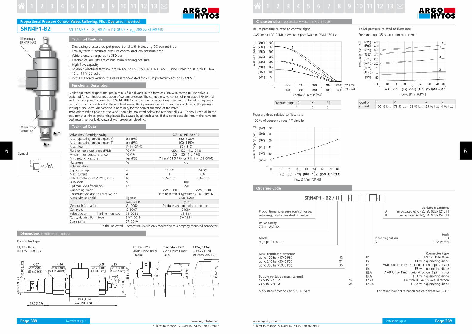
SRN4P1-B2 7/8-14 UNF Qmax
60 l/min (16 GPM) pmax
350 bar (5100 PSI)
T
P
T
37 (
1.4
6) 4
1,5
(1.6
3)
49,4 (1.95)
27 24
50+5 Nm
(37+3.7 lbf.ft)
30+2 Nm
(22.1+1.48 lbf.ft)
27 139+5 Nm
(6.6+3.7 lbf.ft)
8+2 Nm
(5.9+1.5 lbf.ft)
5
7/8
-14-U
NF-
2A
15,8
2 (
0.6
2)
38 (
1.5
0)
45,5
(1.7
9)
42 (
1.6
5)
12 ( . )max. 8 5 0632 28,5 (1. )
+pp
Subject to change · SRN4P1-B2_5138_1en_02/2016
www.argo-hytos.comPage 1
Proportional Pressure Control Valve, Relieving, Pilot Operated, Inverted
Technical Features
Functional Description
Technical Data
A pilot operated proportional pressure relief spool valve in the form of a screw-in cartridge. The valve is designed for continuous regulation of system pressure. The complete valve consist of pilot stage SRN1P1-A2 and main stage with connection 7/8-14 UNF. To set the minimum cracking pressure use the adjusting screw (s=5) which incorporates also the air bleed screw. Back pressure on port T becomes additive to the pressure setting of the valve. Air bleeding is necessary for the correct function of the valve. Installation: When possible, the valve should be mounted below the reservoir oil level. This will keep oil in the actuator at all times, preventing instability caused by air enclosures. If this is not possible, mount the valve for best results vertically downward with proper air bleeding.
Dimensions in millimeters (inches)
› Decreasing pressure output proportional with increasing DC current input
› Low hysteresis, accurate pressure control and low pressure drop
› Wide pressure range up to 350 bar
› Mechanical adjustment of minimum cracking pressure
› High low capacity
› Solenoid electrical terminal option acc. to EN 175301-803-A, AMP Junior Timer, or Deutsch DT04-2P
› 12 or 24 V DC coils
› In the standard version, the valve is zinc-coated for 240 h protection acc. to ISO 9227
Valve size / Cartridge cavity 7/8-14 UNF-2A / B2
Max. operating pressure (port P) bar (PSI) 350 (5080)
Max. operating pressure (port T) bar (PSI) 100 (1450)
Max. low l/min (GPM) 60 (15.9)
Fluid temperature range (FPM) °C (°F) -20...+120 (-4...+248)
Ambient temperature range °C (°F) -20...+80 (-4...+176)
Min. setting pressure bar (PSI) 7 bar (101.5 PSI) for 5 l/min (1.32 GPM)
Hysteresis % < 5
Solenoid data
Supply voltage V 12 DC 24 DC
Max. current A 1 0.6
Rated resistance at 20 °C (68 °F) Ω 6.5±5 % 20.6±5 %
Duty cycle % 100
Optimal PWM frequency Hz 250
Quenching diode BZW06-19B BZW06-33B
Enclosure type acc. to EN 60529** (acc.to terminal type) IP65 / IP67 / IP69K
Mass with solenoid kg (Ibs) 0.58 (1.28)
Data Sheet Type
General information GI_0060 Products and operating conditions
Coil types C_8007 C19B*
Valve bodies In-line mounted SB_0018 SB-B2*
Cavity details / Form tools SMT_0019 SMT-B2*
Spare parts SP_8010
**The indicated IP protection level is only reached with a properly mounted connector.
Main stageSR6H-B2
Pilot stageSRN1P1-A2
Connector type
Symbol
E1, E2 - IP65EN 175301-803-A
E3A, E4A - IP67AMP Junior Timer - axial
E12A, E13A - IP67 / IP69K Deutsch DT04-2P
E3, E4 - IP67AMP Junior Timer - radial
Datasheet pg. 1
SRN4P1 - B2 / H - -
AB
122135
E1E2E3E4E3AE4AE12AE13A
1224
0 200
150
200
100
350
400
800400 600 1000
50( )725
360240 600480120
300
250
( )1450
( )2180
( )2900
( )3630
( )4350
( )5080
( )5800
1
2
3
(1450)
(2175)
(725)
(4350)
(5075)
(2900)
(3625)
100
150
50
200
250
400(5800)
350
300
1
2
4
5
3
0 10 20 30 40 50 60 70 80
(2.6) (5.3) (10.6) (13.2) (15.9) (21.1)(7.9) (18.5)
450(6525)
0
15
20
10
10
5( . )72 5
30
25
( )140
( )218
( )290
( )363
( )435
20 30 40 50 60 70 80
(2.6) (5.3) (10.6) (13.2) (15.9) (21.1)(7.9) (18.5)
Subject to change · SRN4P1-B2_5138_1en_02/2016
www.argo-hytos.com Page 2
Relief pressure related to control signal Relief pressure related to low rate
Control current Ic [mA]
Pre
ssure
p [
bar
(PSI)]
Flow Q [l/min (GPM)]
12 V coil
24 V coil
Q=5 l/min (1.32 GPM), pressure in port T=0 bar, PWM 160 Hz
Pressure drop related to low rate
100 % of control current, P-T direction
Flow Q [l/min (GPM)]
Pre
ssure
p [
bar
(PSI)]
Pre
ssu
re d
rop
∆p
[b
ar
(PSI)]
Proportional pressure control valve, relieving, pilot operated, inverted
Surface treatmentzinc-coated (ZnCr-3), ISO 9227 (240 h)
zinc-coated (ZnNi), ISO 9227 (520 h)
No designationV
SealsNBR
FPM (Viton)
ModelHigh performance
Valve cavity7/8-14 UNF-2A
Max. regulated pressureup to 120 bar (1740 PSI)up to 210 bar (3046 PSI)up to 350 bar (5076 PSI)
Connector typeEN 175301-803-A
E1 with quenching diodeAMP Junior Timer - radial direction (2 pins; male)
E3 with quenchind diodeAMP Junior Timer - axial direction (2 pins; male)
E3A with quenchind diodeDeutsch DT04-2P - axial direction
E12A with quenching diode
Supply voltage / max. current12 V DC / 1.0 A24 V DC / 0.6 A
Main stage ordering key: SR6H-B2/HV For other solenoid terminals see data sheet No. 8007
Pressure range 35, various control currents
Pressure range 12 21 35
1 2 3
Characteristics measured at ν = 32 mm2/s (156 SUS)
Ordering Code
Controlcurrent
1 2 3 4 5
100 % Imax 75 % Imax 25 % Imax 25 % Imax 0 % Imax
Datasheet pg. 2Page 388 Page 389
6 6
3 4 5 6 7 8 9 10 11 12 131 2 3 4 5 6 7 8 9 10 11 12 131 2

PP2P1-W3 Size D20 Qmax
20 l/min (5 GPM) pmax
50 bar (700 PSI)
23(0
.91)
5,4(0.51)
11(0.43) 66,2(2.61)
24(0
.95)
84(3.31)
34,2
(1.3
)
40(1.58)
M8
19,9
(0.7
8)
18,9
(0.7
4)
16,9
(0.6
7)
Model Code no mesh screen with mesh screen
Symbol
Subject to change · PP2P1-W3_5125_1en_08/2016
www.argo-hytos.comPage 1
Proportional Pressure Control Valve, Reducing - Relieving, Direct-Acting, Slip-In Style
Technical Features
Functional Description
Technical Data
A direct-operated, spool-type hydraulic pressure reducing valve in the form of a slip-in cartridge. Reduced pressure output is proportional to DC current input. This valve is intended for use as a pressure limiting device. Note: Consult factory for special OEM versions of this product.
› Excellent stability throughout low range with rapid response to proportional current input change
› Low hysteresis, accurate pressure control and low pressure drop through CFD optimized low paths
› Precise pressure control vs current and excellent repeatability
› Integrated relief function for protection against pressure peaks
› Solenoid electrical terminal AMP Junior Timer or Deutsch DT04-2P
› 12 or 24 V DC coils
› Compact design with reduced solenoid dimensions for production cost savings
› High low capacity and low coil power consumption
› Optional mesh screen
› In the standard version, the valve is zinc-coated for 240 h protection acc. to ISO 9227
Dimensions in millimeters (inches)
Connector type
9+2 Nm(6.6+1.5 lbf.ft)
6
E12A, E13A - IP67 / IP69KDeutsch DT04-2P
E3, E4 - IP67AMP Junior Timer
Valve size / Cartridge cavity D20 / W3 Max. operating pressure (port P) bar (PSI) 50 (730)Max. regulated pressure (port A) bar (PSI) 20 (290) 25 (363) 32 (460)Max. low rate P-A l/min (GPM) 20 (5.3) 20 (5.3) 16 (4.2)Fluid temperature range °C (°F) -30 ...90 (-22 ...194), +100 (212) short-timeAmbient temperature range °C (°F) -30 ...90 (-22 ...194), +100 (212) short-timeResponse time at 100% signal ms < 50Solenoid dataSupply voltage V 12 DC 24 DCMax. current A 1 1Rated resistance at 20 °C (68 °F) Ω 7.2±6.5 % 11.2±6.5 %Duty cycle % 100Optimal PWM frequency Hz signal100Quenching diode BZW06-28B BZW06-33BEnclosure type acc. to EN 60529** (acc.to terminal type) IP 67 / IP 69K Mass kg (Ibs) 0.4 (0.88)
Data Sheet TypeGeneral information GI_0060 Products and operating conditionsValve bodies In-line mounted SB_0018 SB-W3-*Cavity details SMT_0019 SB-W3-*Spare parts SP_8010
**The indicated IP protection level is only reached with a properly mounted connector.
Datasheet pg. 1
PP2P1 - W3/ - -
1224
202532
7
6
5
4
3
1
2
(14.5)
(29.0)
(43.5)
(58.0)
(72.5)
(87.0)
( )100.5
(1.05) (2.11) (3.17) (4.23) (5.28)
0 4 8 12 16 20
P-A
A-T
7
6
5
4
3
1
2
(14.5)
(29.0)
(43.5)
(58.0)
(72.5)
(87.0)
( )100.5
(1.05) (2.11) (3.17) (4.23) (5.28)
0 4 8 12 16 20
A-T
P-A
PP2P1-W3/20-12
PP2P1-W3/25-12
PP2P1-W3/32-12
( )145
( )218
( )73
( )435
( )508
( )290
( )363
0 200 400 600 800 1000
10
15
5
30
35
20
25
1200
PP2P1- W3/25-12
PP2P1- W3/32-24
PP2P1- W3/20-12
2010
(1.3) (2.6)
1
2
4
3
PP2P1-W3/20-12
0
(145)
(73)
(290)
10
5
20
5
(5.3)
0
Subject to change · PP2P1-W3_5125_1en_08/2016
www.argo-hytos.com Page 2
Ordering Code
Proportional pressure control valve,reducing - relieving, direct-acting,slip-in style
Max. regulated pressure20 bar (290 PSI)25 bar (363 PSI)32 bar (464 PSI)
Valve cavityD20 mm (0.79 in)
Surface treatmentzinc-coated (ZnCr-3), ISO 9227 (240 h)
zinc-coated (ZnNi), ISO 9227 (520 h)
Supply voltage / max. current12 V DC / 1 A24 V DC / 1 A
Connector AMP Junior Timer - radial direction (2 pins; male)
E3 with quenching diode Deutsch DT04-2P - axial direction
E12A with quenching diode
Characteristics measured at ν = 32 mm2/s (156 SUS)
No designationSP-125
Mesh screenwithout mesh screen
port P, 125 microns
No designationV
SealsNBR
FPM (Viton)
Pressure drop related to low ratePressure drop related to low rate
A-T, Valve coil de-energized (reducing function)P-A, Valve coil energized (relieving function)
A-T, Valve coil de-energized (reducing function)P-A, Valve coil energized (relieving function)
AB
E3E4E12AE13A
Pre
ssure
diffe
rence
Δp [bar
(PSI)]
Pre
ssure
diffe
rence
Δp [bar
(PSI)]
Pre
ssure
p [bar
(PSI)]
Reduced pressure related to control signal
Port A, range 0 - 20 bar (290 PSI) Port A, range 0 - 32 bar (464 PSI)Port P, Inlet pressure 50 bar (730 PSI)Q = 0 lpm (GPM)
Flow Q [l/min (GPM)]Flow Q [l/min (GPM)]
Curent [mA]
Reduce
d P
ress
ure
p [b
ar
(PSI)]
Flow Q [l/min (GPM)]
Reducing pressure related to low rate
Reducing Function P - A
Besides the shown, commonly used valve versions other special models are available.Contact our technical support for their identiication, feasibility and operating limits.
Control signal1 40 %2 60 %3 80 %4 100 %
Datasheet pg. 2Page 390 Page 391
6 6
3 4 5 6 7 8 9 10 11 12 131 2 3 4 5 6 7 8 9 10 11 12 131 2
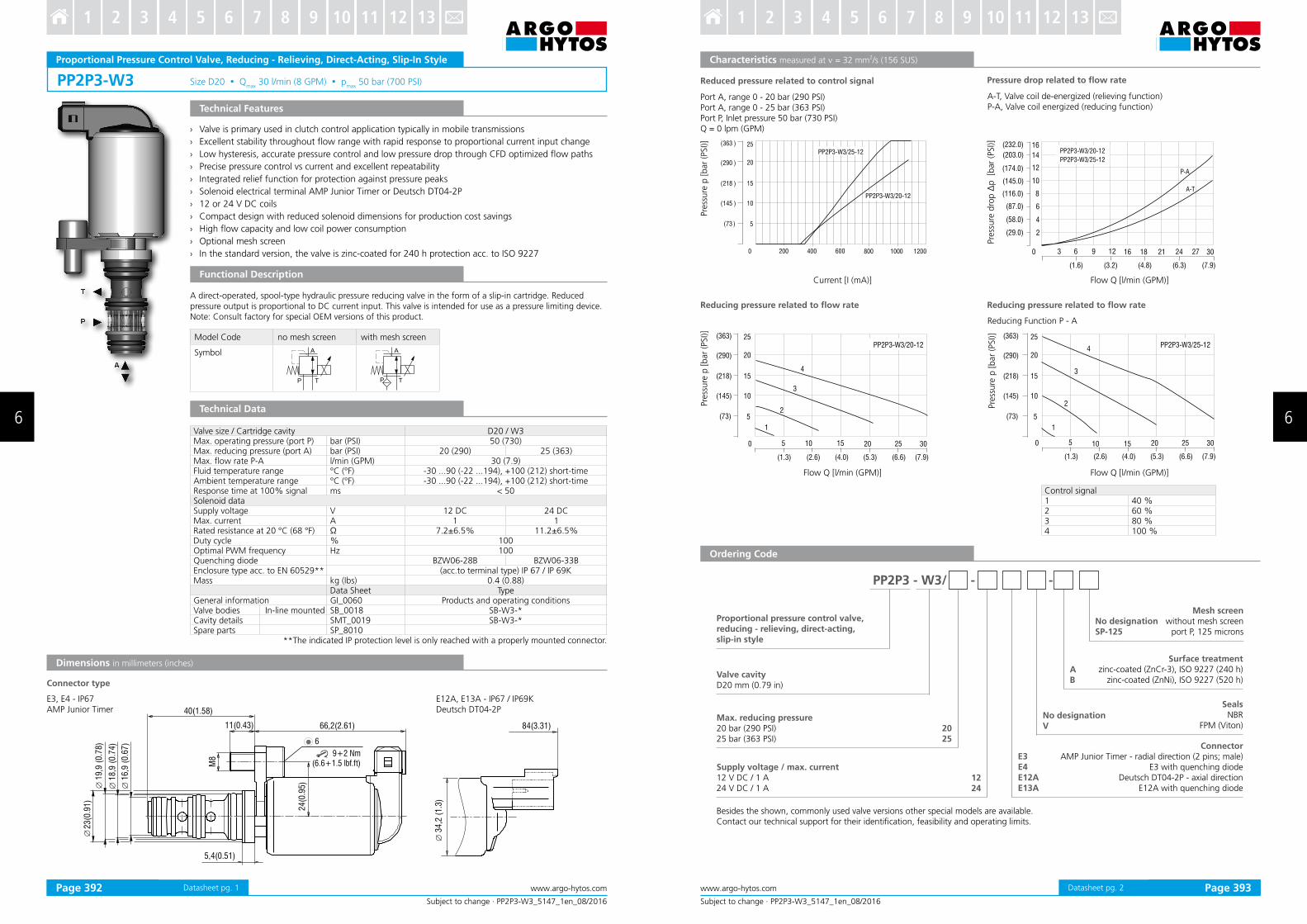
PP2P3-W3 Size D20 Qmax
30 l/min (8 GPM) pmax
50 bar (700 PSI)
Model Code no mesh screen with mesh screen
Symbol
23(0
.91)
5,4(0.51)
11(0.43) 66,2(2.61)
24(0
.95)
84(3.31)
34,2
(1.3
)
40(1.58)
M8
19,9
(0.7
8)
18,9
(0.7
4)
16,9
(0.6
7)
Subject to change · PP2P3-W3_5147_1en_08/2016
www.argo-hytos.comPage 1
Proportional Pressure Control Valve, Reducing - Relieving, Direct-Acting, Slip-In Style
Technical Features
Functional Description
Technical Data
A direct-operated, spool-type hydraulic pressure reducing valve in the form of a slip-in cartridge. Reduced pressure output is proportional to DC current input. This valve is intended for use as a pressure limiting device. Note: Consult factory for special OEM versions of this product.
› Valve is primary used in clutch control application typically in mobile transmissions
› Excellent stability throughout low range with rapid response to proportional current input change
› Low hysteresis, accurate pressure control and low pressure drop through CFD optimized low paths
› Precise pressure control vs current and excellent repeatability
› Integrated relief function for protection against pressure peaks
› Solenoid electrical terminal AMP Junior Timer or Deutsch DT04-2P
› 12 or 24 V DC coils
› Compact design with reduced solenoid dimensions for production cost savings
› High low capacity and low coil power consumption
› Optional mesh screen
› In the standard version, the valve is zinc-coated for 240 h protection acc. to ISO 9227
Valve size / Cartridge cavity D20 / W3 Max. operating pressure (port P) bar (PSI) 50 (730)Max. reducing pressure (port A) bar (PSI) 20 (290) 25 (363)Max. low rate P-A l/min (GPM) 30 (7.9)Fluid temperature range °C (°F) -30 ...90 (-22 ...194), +100 (212) short-timeAmbient temperature range °C (°F) -30 ...90 (-22 ...194), +100 (212) short-timeResponse time at 100% signal ms < 50Solenoid dataSupply voltage V 12 DC 24 DCMax. current A 1 1Rated resistance at 20 °C (68 °F) Ω 7.2±6.5% 11.2±6.5%Duty cycle % 100Optimal PWM frequency Hz 100Quenching diode BZW06-28B BZW06-33BEnclosure type acc. to EN 60529** (acc.to terminal type) IP 67 / IP 69K Mass kg (Ibs) 0.4 (0.88)
Data Sheet TypeGeneral information GI_0060 Products and operating conditionsValve bodies In-line mounted SB_0018 SB-W3-*Cavity details SMT_0019 SB-W3-*Spare parts SP_8010
**The indicated IP protection level is only reached with a properly mounted connector.
Dimensions in millimeters (inches)
Connector type
9+2 Nm(6.6+1.5 lbf.ft)
6
E12A, E13A - IP67 / IP69KDeutsch DT04-2P
E3, E4 - IP67AMP Junior Timer
Datasheet pg. 1
PP2P3 - W3/ - -
1224
2025
30
( )29.0
(87 0).
(203 ).0
(232.0)
(116 ).0
(145 0).
0 3 12 18
4
6
2
12
16
8
10
246 9 16 21 27
(58. )0
14
(174 ).0 P-A
(1.6) (3.2) (4.8) (6.3) (7.9)
A-T
PP2P3-W3/20-12
PP2P3-W3/25-12
( )145
( )218
( )73
( )290
( )363
0 200 400 600 800 1000
10
15
5
20
25
1200
PP2P3-W3/25-12
PP2P3-W3/20-12
300 15 255 10 20
(1.3) (2.6) (4.0) (5.3) (7.9)
( )145
( )218
( )73
( )290
( )363
10
15
5
20
25
1
2
4
3
PP2P3-W3/20-12
(6.6)
( )145
( )218
( )73
( )290
( )363
10
15
5
20
25
1
2
4
3
PP2P3-W3/25-12
300 15 255 10 20
(1.3) (2.6) (4.0) (5.3) (7.9)(6.6)
Subject to change · PP2P3-W3_5147_1en_08/2016
www.argo-hytos.com Page 2
Ordering Code
Proportional pressure control valve,reducing - relieving, direct-acting,slip-in style
Max. reducing pressure20 bar (290 PSI)25 bar (363 PSI)
Valve cavityD20 mm (0.79 in)
Surface treatmentzinc-coated (ZnCr-3), ISO 9227 (240 h)
zinc-coated (ZnNi), ISO 9227 (520 h)
Supply voltage / max. current12 V DC / 1 A24 V DC / 1 A
Connector AMP Junior Timer - radial direction (2 pins; male)
E3 with quenching diode Deutsch DT04-2P - axial direction
E12A with quenching diode
Characteristics measured at ν = 32 mm2/s (156 SUS)
Pre
ssure
p [bar
(PSI)]
Pre
ssure
p [bar
(PSI)]
Flow Q [l/min (GPM)] Flow Q [l/min (GPM)]
No designationSP-125
Mesh screenwithout mesh screen
port P, 125 microns
No designationV
SealsNBR
FPM (Viton)
Pre
ssure
p [bar
(PSI)]
Flow Q [l/min (GPM)]
Pre
ssure
dro
p ∆
p [b
ar
(PSI)]
Current [I (mA)]
Reduced pressure related to control signal Pressure drop related to low rate
Port A, range 0 - 20 bar (290 PSI) Port A, range 0 - 25 bar (363 PSI)Port P, Inlet pressure 50 bar (730 PSI)Q = 0 lpm (GPM)
A-T, Valve coil de-energized (relieving function)P-A, Valve coil energized (reducing function)
Reducing pressure related to low rate Reducing pressure related to low rate
AB
E3E4E12AE13A
Reducing Function P - A
Besides the shown, commonly used valve versions other special models are available.Contact our technical support for their identiication, feasibility and operating limits.
Control signal1 40 %2 60 %3 80 %4 100 %
Datasheet pg. 2Page 392 Page 393
6 6
3 4 5 6 7 8 9 10 11 12 131 2 3 4 5 6 7 8 9 10 11 12 131 2

PVRM1-063/S M20x1.5 Qmax 20 l/min (5 GPM) pmax 50 bar (700 PSI)
A
T
P
38 (
1.5
0)
45,5
(1.7
9)
30 (
1.1
8)
115 (4.53)
27
37 (
1.4
6)
27
70 (2.76)
42 (
1.6
5)
30+5 Nm
(22.1+3.7 lbf.ft)
9+5 Nm
(6.6+3.7 lbf.ft)
15,4
(0.6
)
M20x1
,5
16,9
(0.7
)
49,4 (1.95)
Model Code no mesh screen with mesh screen
Symbol
Subject to change · PVRM1-063/S_5108_1en_02/2016
www.argo-hytos.comPage 1 Datasheet pg. 1
Proportional Pressure Control Valve, Reducing - Relieving, Direct-Acting
Technical Features
Functional Description
Technical Data
› Excellent stability throughout low range with rapid response to proportional current input change
› Low hysteresis, accurate pressure control and low pressure drop
› Precise pressure control vs current and excellent repeatability
› Integrated relief function for protection against pressure peaks
› Solenoid electrical terminal acc. to EN 175301-803-A, AMP Junior Timer, or Deutsch DT04-2P
› 12 or 24 V DC coils
› Optional mesh screen
› In the standard version, the valve is zinc-coated for 240 h protection acc. to ISO 9227
A direct-operated, spool-type hydraulic pressure reducing-relieving valve in the form of a screw-in cartridge. Reduced pressure output is proportional to DC current input. This valve is intended for use as a pressure limiting device. Note: Consult factory for special OEM versions of this product.
Valve size / Cartridge cavity M20x1.5 / QE3Max. operating pressure (port P) bar (PSI) 50 (730)Max. reduced pressure (port A) bar (PSI) 20 (290) 32 (464)Max. low rate P-A l/min (GPM) 20 (5.3)Fluid temperature range °C (°F) -30 ...90 (-22 ...194), +100 (212) short-timeAmbient temperature range °C (°F) -30 ...90 (-22 ...194), +100 (212) short-timeResponse time at 100% signal ms < 50Solenoid dataSupply voltage V 12 DC 24 DCMax. current A 1 0,75Rated resistance at 20 °C (68 °F) Ω 7.1 ± 6.5% 20.6 ± 6.5%Duty cycle % 100Optimal PWM frequency Hz 100Quenching diode BZW06-28B BZW06-33BEnclosure type acc. to EN 60529** DIN / AMP / Deutsch DT04-2P IP65 / IP67 / IP69KMass with solenoid kg (Ibs) 0.4 (0.88)
Data sheet TypeGeneral information GI_0060 Products and operating conditionsCavity details SMT_0019 SMT-QE3*Spare parts SP_8010
**The indicated IP protection level is only reached with a properly mounted connector.
E1, E2 - IP65EN 175301-803-A
E3, E4 - IP67AMP Junior Timer - radial
E3A, E4A - IP67AMP JuniorTimer - axial
E12A, E13A - IP67/ IP69KDeutsch DT04-2P
Dimensions in millimeters (inches)
Connector type
PVRM1 - 063 / S - - -
1224
E1E2E3E4E3AE4AE12AE13A
2032
(465)
8
12
4
24
16
20
(120)
(230)
1 0050 500 1000
32
28
(350)
250 500 750
( )43.5
( )72.5
( )87.0
0 5 10 15
2
3
1
6
4
5
20
( )14.5
( )29.0
( )58.0
7( )101.5
( )1.3 ( )2.6 ( )4.0 ( )5.3
A T
P A
AB
Subject to change · PVRM1-063/S_5108_1en_02/2016
www.argo-hytos.com Page 2Datasheet pg. 2
Ordering Code
Proportional pressure control valve, reducing - relieving,direct-acting
Modelscrew-in cartridge
Max. reduced pressure20 bar (290 PSI)32 bar (464 PSI)
Valve cavityM20x1.5 / QE3 Surface treatment
zinc-coated (ZnCr-3), ISO 9227 (240 h)zinc-coated (ZnNi), ISO 9227 (520 h)
No designationV
SealsNBR
FPM (Viton)
Supply voltage / max. current12 V DC / max. 1 A24 V DC / max. 0.75 A
ConnectorEN 175301-803-A
E1 with quenching diode AMP Junior Timer - radial direction (2 pins; male)
E3 with quenching diodeAMP Junior Timer - axial direction (2 pins; male)
E3A with quenching diode Deutsch DT04-2P - axial direction
E12A with quenching diode
Characteristics measured at ν = 32 mm2/s (156 SUS)
Pre
ssure
p [
bar
(PSI)]
Pre
ssure
p [
bar
(PSI)]
Pre
ssu
re d
rop
Δp
[b
ar
(PSI)]
Current [I (mA)]
12 V coil
24 V coil
1000 1200
( )170
( )290
( )350
0 200 400 600
8
12
4
24
16
20
800
( )60
( )120
( )230
600 700400 500200 300100
12 V coil
24 V coil
Flow Q [l/min (GPM)]
PVRM1-063/S*20 PVRM1-063/S*32
No designationSP-125
Mesh screenwithout mesh screen
port P, 125 microns
Reduced pressure related to control signal
Port A, range 0 - 20 bar (290 PSI), Q = 0 lpm (GPM)Port P, inlet pressure 50 bar (730 PSI)
Pressure drop related to low rate
A-T, Valve coil de-energized (relieving function)P-A, Valve coil energized (reducing function)
Current [I (mA)]
Reduced pressure related to control signal
Port A, range 0 - 32 bar (464 PSI), Q = 0 lpm (GPM)Port P, inlet pressure 50 bar (730 PSI)
Page 394 Page 395
6 6
3 4 5 6 7 8 9 10 11 12 131 2 3 4 5 6 7 8 9 10 11 12 131 2
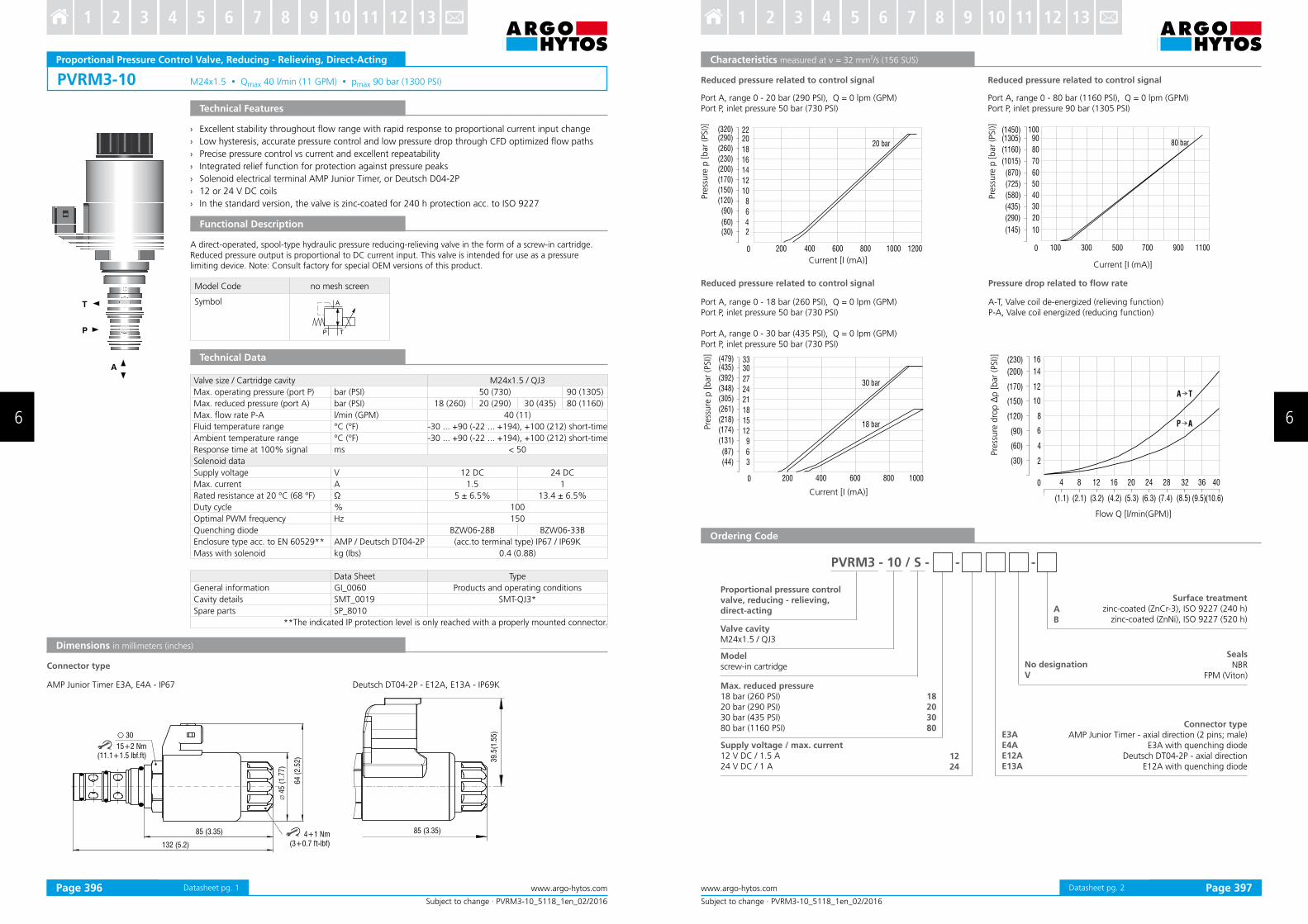
PVRM3-10 M24x1.5 Qmax 40 l/min (11 GPM) pmax 90 bar (1300 PSI)
85 (3.35)
132 (5.2)
64 (
2.5
2)
45 (
1.7
7)
30
39.5
(1.5
5)
85 (3.35) 4+1 Nm (3+0.7 ft-lbf)
15+2 Nm (11.1+1.5 lbf.ft)
Model Code no mesh screen
Symbol
Subject to change · PVRM3-10_5118_1en_02/2016
www.argo-hytos.comPage 1 Datasheet pg. 1
Proportional Pressure Control Valve, Reducing - Relieving, Direct-Acting
Technical Features
Functional Description
Technical Data
› Excellent stability throughout low range with rapid response to proportional current input change
› Low hysteresis, accurate pressure control and low pressure drop through CFD optimized low paths
› Precise pressure control vs current and excellent repeatability
› Integrated relief function for protection against pressure peaks
› Solenoid electrical terminal AMP Junior Timer, or Deutsch D04-2P
› 12 or 24 V DC coils
› In the standard version, the valve is zinc-coated for 240 h protection acc. to ISO 9227
A direct-operated, spool-type hydraulic pressure reducing-relieving valve in the form of a screw-in cartridge. Reduced pressure output is proportional to DC current input. This valve is intended for use as a pressure limiting device. Note: Consult factory for special OEM versions of this product.
AMP Junior Timer E3A, E4A - IP67
Dimensions in millimeters (inches)
Deutsch DT04-2P - E12A, E13A - IP69K
Valve size / Cartridge cavity M24x1.5 / QJ3
Max. operating pressure (port P) bar (PSI) 50 (730) 90 (1305)
Max. reduced pressure (port A) bar (PSI) 18 (260) 20 (290) 30 (435) 80 (1160)
Max. low rate P-A l/min (GPM) 40 (11)
Fluid temperature range °C (°F) -30 ... +90 (-22 ... +194), +100 (212) short-time
Ambient temperature range °C (°F) -30 ... +90 (-22 ... +194), +100 (212) short-time
Response time at 100% signal ms < 50
Solenoid data
Supply voltage V 12 DC 24 DC
Max. current A 1.5 1
Rated resistance at 20 °C (68 °F) Ω 5 ± 6.5% 13.4 ± 6.5%
Duty cycle % 100
Optimal PWM frequency Hz 150
Quenching diode BZW06-28B BZW06-33B
Enclosure type acc. to EN 60529** AMP / Deutsch DT04-2P (acc.to terminal type) IP67 / IP69K
Mass with solenoid kg (Ibs) 0.4 (0.88)
Data Sheet Type
General information GI_0060 Products and operating conditions
Cavity details SMT_0019 SMT-QJ3*
Spare parts SP_8010
**The indicated IP protection level is only reached with a properly mounted connector.
Connector type
PVRM3 - 10 / S - - -
1224
E3AE4AE12AE13A
18203080
AB
( )30
0
10
12
2
18
22
14
16
4
6
8
( )60
( )90
( )120
( )150
( )170
( )200
( )230
( )260
( )320
200 400 600 800 1000
20( )290
1200
20 bar
( )145
0 100
50
60
10
90100
70
80
20
30
40
( )290
( )435
( )580
( )725
( )870
( )1015
( )1160
( )1305( )1450
300 500 700 900 1100
80 bar
( )44
0
15
18
3
27
33
21
24
6
9
12
( )87
( )131
( )174
( )218
( )261
( )305
( )348
( )392
( )479
200 400 600 800 1000
30( )435
30 bar
18 bar
( )30
0 4
10
12
2
14
16
4
6
8
( )60
( )90
( )120
( )150
( )170
( )200
( )230
8 12 16 20 24 28 32 36 40
( )1.1 ( )2.1 ( )3.2 ( )4.2 ( )5.3 ( )8.5( )6.3 ( )7.4 ( )9.5 ( )10.6
A T
P A
Subject to change · PVRM3-10_5118_1en_02/2016
www.argo-hytos.com Page 2Datasheet pg. 2
Ordering Code
Characteristics measured at ν = 32 mm2/s (156 SUS)
Proportional pressure control valve, reducing - relieving,direct-acting
Modelscrew-in cartridge
Max. reduced pressure18 bar (260 PSI)20 bar (290 PSI)30 bar (435 PSI)80 bar (1160 PSI)
Valve cavityM24x1.5 / QJ3
Surface treatmentzinc-coated (ZnCr-3), ISO 9227 (240 h)
zinc-coated (ZnNi), ISO 9227 (520 h)
No designationV
SealsNBR
FPM (Viton)
Supply voltage / max. current12 V DC / 1.5 A24 V DC / 1 A
Connector typeAMP Junior Timer - axial direction (2 pins; male)
E3A with quenching diode Deutsch DT04-2P - axial direction
E12A with quenching diode
Pre
ssure
p [bar
(PSI)]
Current [I (mA)]
Reduced pressure related to control signal
Port A, range 0 - 18 bar (260 PSI), Q = 0 lpm (GPM)Port P, inlet pressure 50 bar (730 PSI)
Port A, range 0 - 30 bar (435 PSI), Q = 0 lpm (GPM)Port P, inlet pressure 50 bar (730 PSI)
Pre
ssure
p [bar
(PSI)]
Current [I (mA)]
Reduced pressure related to control signal
Port A, range 0 - 20 bar (290 PSI), Q = 0 lpm (GPM)Port P, inlet pressure 50 bar (730 PSI)
Flow Q [l/min(GPM)]
Pre
ssure
dro
p Δ
p [bar
(PSI)]
Pressure drop related to low rate
A-T, Valve coil de-energized (relieving function)P-A, Valve coil energized (reducing function)
Current [I (mA)]
Pre
ssure
p [bar
(PSI)]
Port A, range 0 - 80 bar (1160 PSI), Q = 0 lpm (GPM)Port P, inlet pressure 90 bar (1305 PSI)
Reduced pressure related to control signal
Page 396 Page 397
6 6
3 4 5 6 7 8 9 10 11 12 131 2 3 4 5 6 7 8 9 10 11 12 131 2

SP4P1-B4 7/8-14 UNF Qmax
40 l/min (11 GPM) pmax
30 bar (435 PSI)
T
P
A
5
10
15
20
25
30
10 20 30 40 50 60 70 80 90 100
(73)
(145)
(218)
(290)
(363)
(435)
0 0 5 10 15 20 25
2
3
1
4
5
(2.6) (7.9)(5.3)
30
(14.5)
35 40
(10.6)
7
8
6
910
(43.5)
(72.5)
(101.5)
(130.5)(145.0)
(1.3)
Model Code no mesh screen with mesh screen
Symbol
Subject to change · SP4P1-B4_5124_1en_02/2016
www.argo-hytos.comPage 1
Proportional Pressure Control Valve, Reducing - Relieving, Pilot Operated, Screw-In Style
Technical Features
› Excellent stability throughout low range with rapid response to proportional current input change
› Low hysteresis, accurate pressure control and low pressure drop through CFD optimized low paths
› Precise pressure control vs current and excellent repeatability
› Integrated relief function for protection against pressure peaks
› Solenoid electrical terminal: AMP Junior Timer or Deutsch DT04-2P
› 12 or 24 V DC coils
› Compact design with reduced solenoid dimensions for production cost saving
› High low capacity and low coil power consumption
› Optional mesh screen
› In the standard version, the valve is zinc-coated for 240 h protection acc. to ISO 9227
Functional Description
Technical Data
A pilot-operated, spool-type hydraulic pressure reducing valve in the form of a screw-in cartridge. Reduced pressure output is proportional to DC current input. This valve is intended for use as a pressure limiting device. Note: Consult factory for special OEM versions of this product.
Characteristics measured at ν = 32 mm2/s (156 SUS)
Control Signal [%]
Pre
ssure
dro
p ∆
p [
bar
(PSI)]
Flow Q [l/min (GPM)]
Pre
ssure
p [
bar
(PSI)]
Valve size / Cartridge cavity 7/8-14 UNF-2A / B4Max. operating pressure (port P) bar (PSI) 30 (435)Max. reducing pressure (port A) bar (PSI) 25 (363)Max. low rate P-A l/min (GPM) 40 (11)Fluid temperature range °C (°F) -30 ...90 (-22 ...194), +100 (212) short timeAmbient temperature range °C (°F) -30 ...90 (-22 ...194), +100 (212) short timeResponse time at 100 % signal ms < 50Solenoid dataSupply voltage V 12 DC 24 DCMax. current A 0.7 0.35Rated resistance at 20 °C (68 °F) Ω 7.82+5 % 29.5+4.5 %Duty cycle % 100Optimal PWM frequency Hz 200Quenching diode BZW06-28B BZW06-33BEnclosure type acc.to EN 60529** (acc.to terminal type) IP67 / IP69K Mass with solenoid kg (Ibs) 0.3 (0.66)
Data Sheet TypeGeneral information GI_0060 Products and operating conditionsCoil types C_8007 C14B*Valve bodies In-line mounted SB_0018 SB-B4*
Sandwich mounted SB-04(06)_0028 SB-*B4*Cavity details / Form tools SMT_0019 SMT-B4*Spare parts SP_8010
**The indicated IP protection level is only reached with a properly mounted connector.
Reduced pressure related to control signalPort A of range 0 - 25 bar (363 PSI), Q = 0 lpm (GPM)Port P inlet pressure 30 bar ( 435 PSI)measured without mesh screen
Pressure drop related to low rate A-T Valve coil de-energized ( relieving function) P-A Valve coil energized (reducing function)measured without mesh screen
P-A
Datasheet pg. 1
(0.6
9)
61(2.40)
30 (
1.18
)
7/8-
14U
NF-
2B
34 (
1.34
)
63,5(2.50)
17,4
2
19 (
0.75
) 39,5
(1.
55)
61(2.40)
30+5 Nm (22+3.7 ft-lbf)
3+1Nm (2.2+0.7 ft-lbf)
24 2425.4 (1“)
3+1Nm (2.2+0.7 ft-lbf)
( (-5.28) 0 (5.28) (10.56)-10.56)
-40 -30 -20 -10 0 10 20 30 40
5
10
15
20
25
30
(73)
(145)
(218)
(290)
(363)
(435)
0
8
7
6
5
4
3
2
1
1 2 3 4 5 6 7 8 910 20 30 40 50
-5,0
-4,5
-3,5
-3,0
-2,5
-2,0
-1,0
-1,5
-0,5
0
10
20
30
40
50
60
80
70
90
0
60 80 10070 90
------ signal 70 ± 25% signal 55 ± 40%
SP4P1-B4 / - -
AB
2025
1224
E3AE4AE12AE13A
Subject to change · SP4P1-B4_5124_1en_02/2016
www.argo-hytos.com Page 2
Characteristics measured at ν = 32 mm2/s (156 SUS)
Dimensions in millimeters (inches)
Frequency [Hz]
Gain
(A
mplit
ude)
[dB]
Flow Q [l/min (GPM)]
Pre
ssure
p [
bar
(PSI)]
1 2 3 4 5 6 7 8
24% 35% 47% 59% 70% 82% 94% 100%
Phase
[degre
es]
Reducing - relieving pressure related to low rateReducing pressure range 0 - 25 bar (0 - 363 PSI), input 30 bar (435 PSI)various control currentsmeasured without mesh screen
Frequency response characteristicsInlet pressure at port P - 30 bar (435 PSI), low = 0 lpm (GPM)
Connector type
E12A, E13A - IP67 / IP69KDeutsch DT04-2P
Ordering Code
Proportional pressure control valve,reducing - relieving, pilot operated,screw-in style
Surface treatmentzinc-coated (ZnCr-3), ISO 9227 (240 h)
zinc-coated (ZnNi), ISO 9227 (520 h)
Connector type AMP Junior Timer - axial direction (2 pins; male)
E3A with quenching diode Deutsch DT04-2P - axial direction
E12A with quenching diode
Max. reducing pressure20 bar (290 PSI)25 bar (363 PSI)
No designationV
SealsNBR
FPM (Viton)
Supply voltage / max. current12 V DC / 0.7 A24 V DC / 0.35 A
No designationSP-300
Mesh screenwithout mesh screen
port P, 300 microns
Valve cavity7/8-14 UNF
E3A, E4A - IP67AMP Junior Timer
relieving function A-T / reducing function P-A
Datasheet pg. 2Page 398 Page 399
6 6
3 4 5 6 7 8 9 10 11 12 131 2 3 4 5 6 7 8 9 10 11 12 131 2
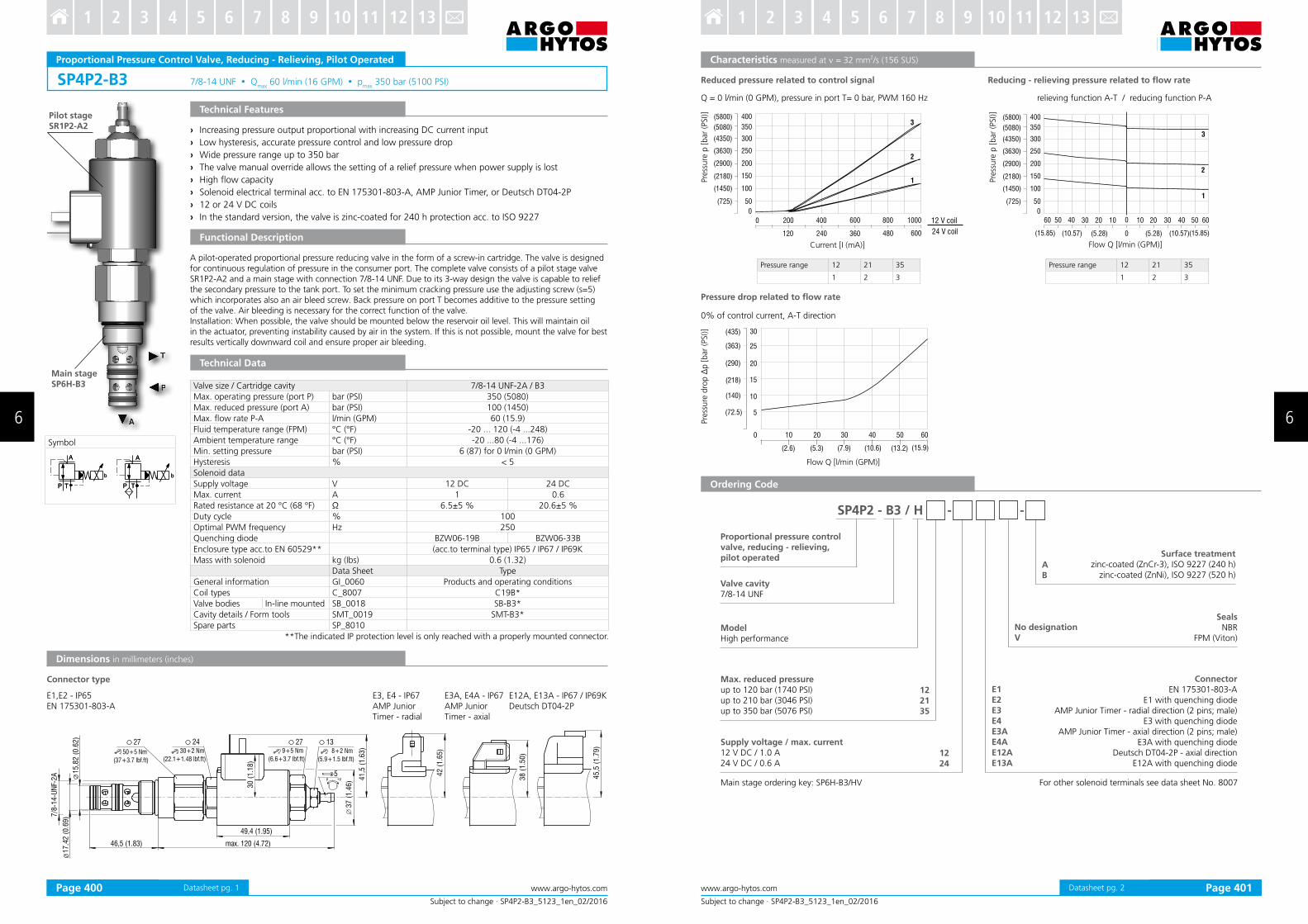
SP4P2-B3 7/8-14 UNF Qmax
60 l/min (16 GPM) pmax
350 bar (5100 PSI)
38 (
1.5
0)
45,5
(1.7
9)
49,4 (1.95)
7/8
-14
-UN
F-2
A
46,5 (1.83) max. 120 (4.72)
37
(1
.46
) 41
,5 (
1.6
3)
15
,82
(0
.62
)
17
,42
(0
.69
)
27 24 27 13
50+5 Nm
(37+3.7 lbf.ft)
30
(1
.18
)
5
30+2 Nm
(22.1+1.48 lbf.ft)
9+5 Nm
(6.6+3.7 lbf.ft)
8+2 Nm
(5.9+1.5 lbf.ft)
42 (
1.6
5)
+pp
b
TP
A
b
TP
A
b
TP
A
b
TP
A
Symbol
Subject to change · SP4P2-B3_5123_1en_02/2016
www.argo-hytos.comPage 1
Proportional Pressure Control Valve, Reducing - Relieving, Pilot Operated
Technical Features
› Increasing pressure output proportional with increasing DC current input
› Low hysteresis, accurate pressure control and low pressure drop
› Wide pressure range up to 350 bar
› The valve manual override allows the setting of a relief pressure when power supply is lost
› High low capacity
› Solenoid electrical terminal acc. to EN 175301-803-A, AMP Junior Timer, or Deutsch DT04-2P
› 12 or 24 V DC coils
› In the standard version, the valve is zinc-coated for 240 h protection acc. to ISO 9227
Functional Description
A pilot-operated proportional pressure reducing valve in the form of a screw-in cartridge. The valve is designed for continuous regulation of pressure in the consumer port. The complete valve consists of a pilot stage valve SR1P2-A2 and a main stage with connection 7/8-14 UNF. Due to its 3-way design the valve is capable to relief the secondary pressure to the tank port. To set the minimum cracking pressure use the adjusting screw (s=5) which incorporates also an air bleed screw. Back pressure on port T becomes additive to the pressure setting of the valve. Air bleeding is necessary for the correct function of the valve.Installation: When possible, the valve should be mounted below the reservoir oil level. This will maintain oilin the actuator, preventing instability caused by air in the system. If this is not possible, mount the valve for best results vertically downward coil and ensure proper air bleeding.
Technical Data
Valve size / Cartridge cavity 7/8-14 UNF-2A / B3
Max. operating pressure (port P) bar (PSI) 350 (5080)
Max. reduced pressure (port A) bar (PSI) 100 (1450)
Max. low rate P-A l/min (GPM) 60 (15.9)
Fluid temperature range (FPM) °C (°F) -20 ... 120 (-4 ...248)
Ambient temperature range °C (°F) -20 ...80 (-4 ...176)
Min. setting pressure bar (PSI) 6 (87) for 0 l/min (0 GPM)
Hysteresis % < 5
Solenoid data
Supply voltage V 12 DC 24 DC
Max. current A 1 0.6
Rated resistance at 20 °C (68 °F) Ω 6.5±5 % 20.6±5 %
Duty cycle % 100
Optimal PWM frequency Hz 250
Quenching diode BZW06-19B BZW06-33B
Enclosure type acc.to EN 60529** (acc.to terminal type) IP65 / IP67 / IP69K
Mass with solenoid kg (Ibs) 0.6 (1.32)
Data Sheet Type
General information GI_0060 Products and operating conditions
Coil types C_8007 C19B*
Valve bodies In-line mounted SB_0018 SB-B3*
Cavity details / Form tools SMT_0019 SMT-B3*
Spare parts SP_8010
**The indicated IP protection level is only reached with a properly mounted connector.
Pilot stageSR1P2-A2
Main stageSP6H-B3
Dimensions in millimeters (inches)
Connector type
E1,E2 - IP65EN 175301-803-A
E3A, E4A - IP67AMP JuniorTimer - axial
E12A, E13A - IP67 / IP69K Deutsch DT04-2P
E3, E4 - IP67AMP JuniorTimer - radial
Datasheet pg. 1 Datasheet pg. 1
0
200
150
200
100
350
400
800400 600 1000
50( )725
2
1
3
360240 600480120
300
250
( )1450
( )2180
( )2900
( )3630
( )4350
( )5080
( )5800
0
0
150
200
100
350
400
2010 30
50( )725
2
1
(5.28) (15.85)(10.57)
300
250
( )1450
( )2180
( )2900
( )3630
( )4350
( )5080
( )5800
0
0
40 50 601030405060 20
(5.28)(10.57)(15.85)
3
Pressure range 12 21 35
1 2 3
SP4P2 - B3 / H - -
1224
E1E2E3E4E3AE4AE12AE13A
122135
AB
12 V coil
24 V coil
0
15
20
10
10
5( . )72 5
30
25
( )140
( )218
( )290
( )363
( )435
20 30 40 50 60
(2.6) (5.3) (10.6) (13.2) (15.9)(7.9)
Pressure range 12 21 35
1 2 3
Subject to change · SP4P2-B3_5123_1en_02/2016
www.argo-hytos.com Page 2
Characteristics measured at ν = 32 mm2/s (156 SUS)
Proportional pressure controlvalve, reducing - relieving,pilot operated
ModelHigh performance
Max. reduced pressureup to 120 bar (1740 PSI)up to 210 bar (3046 PSI)up to 350 bar (5076 PSI)
Valve cavity7/8-14 UNF
Surface treatmentzinc-coated (ZnCr-3), ISO 9227 (240 h)
zinc-coated (ZnNi), ISO 9227 (520 h)
No designationV
SealsNBR
FPM (Viton)
Supply voltage / max. current12 V DC / 1.0 A24 V DC / 0.6 A
ConnectorEN 175301-803-A
E1 with quenching diode AMP Junior Timer - radial direction (2 pins; male)
E3 with quenching diodeAMP Junior Timer - axial direction (2 pins; male)
E3A with quenching diode Deutsch DT04-2P - axial direction
E12A with quenching diode
Main stage ordering key: SP6H-B3/HV For other solenoid terminals see data sheet No. 8007
Reduced pressure related to control signal
Q = 0 l/min (0 GPM), pressure in port T= 0 bar, PWM 160 Hz
Pressure drop related to low rate
0% of control current, A-T direction
Reducing - relieving pressure related to low rate
relieving function A-T / reducing function P-A
Pre
ssu
re d
rop
Δp
[bar
(PSI)]
Flow Q [l/min (GPM)]
Current [I (mA)]
Pre
ssure
p [
bar
(PSI)]
Flow Q [l/min (GPM)]
Pre
ssure
p [
bar
(PSI)]
Ordering Code
Datasheet pg. 2Page 400 Page 401
6 6
3 4 5 6 7 8 9 10 11 12 131 2 3 4 5 6 7 8 9 10 11 12 131 2

SPN4P1-B3 7/8-14 UNF Qmax
60 l/min (16 GPM) pmax
350 bar (5100 PSI)
T3
8 (
1.5
0)
45
,5 (
1.7
9)
42
(1
.65
)
49,4 (1.95)
128 (5.06)46,5 (1.83)
37
(1
.46
) 41
,5 (
1.6
3)
27 24
50+5 Nm
(37+3.7 lbf.ft)
30+2 Nm
(22.1+1.48 lbf.ft)
27 139+5 Nm
(6.6+3.7 lbf.ft)
8+2 Nm
(5.9+1.5 lbf.ft)
5
7/8
-14
-UN
F-2
A
15
,82
(0
.62
)
17
,42
(0
.69
)
+pp
Symbol
Subject to change · SPN4P1-B3_5139_1en_02/2016
www.argo-hytos.comPage 1
Proportional Pressure Control Valve, Reducing - Relieving, Pilot Operated, Inverted
Technical Features
› Decreasing pressure output proportional with increasing DC current input
› Low hysteresis, accurate pressure control and low pressure drop
› Wide pressure range up to 350 bar
› Mechanical adjustment of minimum cracking pressure
› High low capacity
› Solenoid electrical terminal acc. to EN 175301-803-A, AMP Junior Timer, Deutsch DT04-2P
› 12 or 24 V DC coils
› In the standard version, the valve is zinc-coated for 240 h protection acc. to ISO 9227
Functional Description
A pilot-operated proportional pressure reducing valve in the form of a screw-in cartridge. The valve is designed for continuous regulation of pressure in the consumer port. The complete valve consists of a pilot stage valve SRN1P1-A2 and a main stage with connection 7/8-14 UNF. Due to its 3-way design the valve is capable to relief the secondary pressure to the tank port. To set the minimum cracking pressure use the adjusting screw (s=5) which incorporates also an air bleed screw. Back pressure on port T becomes additive to the pressure setting of the valve. Air bleeding is necessary for the correct function of the valve.Installation: When possible, the valve should be mounted below the reservoir oil level. This will maintain oilin the actuator, preventing instability caused by air in the system. If this is not possible, mount the valve for best results vertically downward coil and ensure proper air bleeding.
Dimensions in millimeters (inches)
Technical Data
Pilot stageSRN1P1-A2
Main stageSP6H-B3
Valve size / Cartridge cavity 7/8-14 UNF-2A / B3Max. operating pressure (port P) bar (PSI) 350 (5080)Max. operating pressure (port T) bar (PSI) 100 (1450)Max. low l/min (GPM) 60 (15.9)Fluid temperature range (FPM) °C (°F) -20 ... +120 (-4 ... 248)Ambient temperature range °C (°F) -20 ... +80 (-4 ... 176)Min. setting pressure bar (PSI) 6 (87) for 0 l/min (0 GPM)Hysteresis % < 5Solenoid dataSupply voltage V 12 DC 24 DCMax. current A 1 0.6Rated resistance at 20 °C (68 °F) Ω 6.5±5 % 20.6±5 %Duty cycle % 100Optimal PWM frequency Hz 250Quenching diode BZW06-19B BZW06-33BEnclosure type acc.to EN 60529** (acc.to terminal type) IP65 / IP67 / IP69K
Mass with solenoid kg (Ibs) 0.6 (1.32)Data Sheet Type
General information GI_0060 Products and operating conditionsCoil types C_8007 C19B*Valve bodies In-line mounted SB_0018 SB-B3*Cavity details / Form tools SMT_0019 SMT-B3*Spare Parts SP_8010
**The indicated IP protection level is only reached with a properly mounted connector.
Connector type
E1, E2 - IP65EN 175301-803-A
E3A, E4A - IP67AMP Junior Timer - axial
E12A, E13A - IP67 / IP69K Deutsch DT04-2P
E3, E4 - IP67AMP Junior Timer - radial
Datasheet pg. 1
0
15
20
10
10
5( . )72 5
30
25
( )140
( )218
( )290
( )363
( )435
20 30 40 50 60
(2.6) (5.3) (10.6) (13.2) (15.9)(7.9)
(1450)
(2175)
(725)
(4350)
(5075)
(29001)
(3625)
100
150
50
200
250
400(5800)
350
300
1
2
3
0120200
240400
360600
480800
6001000
0
150
200
100
350
400
20
50(725)
(5.3) (15.9)(10.6)
300
250
(1450)
(2180)
(2900)
(3630)
(4350)
(5080)
(5800)
0
0
40 604060 20
(5.3)(10.6)(15.9)
2
1
4
5
3
SPN4P1 - B3 / H - -
1224
E1E2E3E4E3AE4AE12AE13A
122135
AB
Subject to change · SPN4P1-B3_5139_1en_02/2016
www.argo-hytos.com Page 2
Characteristics measured at ν = 32 mm2/s (156 SUS)
Pressure drop D
p [b
ar
(PSI)]
Current I [mA]
Pre
ssure
p [
bar
(PSI)]
Pressure range 12 21 35
1 2 3
Pre
ssure
p [
bar
(PSI)]
Flow Q [l/min (GPM)]
12 V coil
24 V coil
Ordering Code
Proportional pressure control valve,reducing - relieving, pilot operated,inverted
ModelHigh performance
Max. reduced pressureup to 120 bar (1740 PSI)up to 210 bar (3046 PSI)up to 350 bar (5076 PSI)
Valve cavity7/8-14 UNF
Supply voltage / max. current12 V DC / 1.0 A24 V DC / 0.6 A
Main stage ordering key: SP6H-B3/HV
Surface treatmentzinc-coated (ZnCr-3), ISO 9227 (240 h)
zinc-coated (ZnNi), ISO 9227 (520 h)
No designationV
SealsNBR
FPM (Viton)
ConnectorEN 175301-803-A
E1 with quenching diode AMP Junior Timer - radial direction (2 pins; male)
E3 with quenching diodeAMP Junior Timer - axial direction (2 pins; male)
E3A with quenching diode Deutsch DT04-2P - axial direction
E12A with quenching diode
For other solenoid terminals see data sheet No. 8007
Reduced pressure related to control signal
Q = 0 l/min (0 GPM), pressure in port T= 0 bar, PWM 160 Hz
Pressure drop related to low rate
Reducing - relieving pressure related to low rate
relieving function A-T / reducing function P-A
100% of control current, A-T direction
Flow Q [l/min (GPM)]
Pressure range 35, Input 400 bar, various control currents
Controlcurrent
1 2 3 4 5
100%Imax 75%Imax 50%Imax 25%Imax 0%Imax
Datasheet pg. 2Page 402 Page 403
6 6
3 4 5 6 7 8 9 10 11 12 131 2 3 4 5 6 7 8 9 10 11 12 131 2

TV2-042/M Size 04 (D02) Qmax
16 l/min (4 GPM) pmax
320 bar (4600 PSI)
3[0.12]
22,5 [0.89]
23,25 [0.92]
4,3
[0.1
7]
12 [
0.4
7]
19,7
[0.7
8]
11,25 [0.44]2,25 [0.09]
20,25 [0.8]
24 [
0.9
4]
0,75 [0.03]
4xM 5 -6Hx13+1/16-2
26,5
[1.0
4]
4,75 [0.19]
A
PT
BG
ISO 4401-02-01-0-05
80 24040 120 200 280 320160
( )2320( )1160 ( )4640( )3480( )580
6
9
3
12
(0.8)
0
(0.8)
(3.2)
(2.4)
(1.6)
6
9
3
12
15
( .6)1
( .4)2
(0.8)
(3.2)
(4.0)
80 24040 120 200 280 320160
( )2320( )1160 ( )4640( )3480( )580
0
Subject to change · TV2-042/M_5167_1en_02/2016
www.argo-hytos.comPage 1
2-Way Pressure Compensator, Spool-Type, Direct-Acting, Modular
Technical Features
Functional Description
Technical Data
› 2-Way pressure compensator, spool-type, direct-acting with subplate interface acc. to ISO 4401, DIN 24340 (CETOP 02)
› Modular design for vertical stacking assemblies with built-in load sensing shuttle valve
› Meter-in and meter-out low control models with integrated by-pass check valves
› The valve keeps the pressure drop between the inlet and the pilot connection at a constant level
› Used as a load sensing valve with proportional directional and low valves to control the low rate independently of pressure variations
› Excellent stability throughout the low range, rapid response to dynamic pressure changes
› Quiet and modulate response to load changes
› Hardened precision parts
› High low capacity
› In the standard version, the valve housing is phosphated and steel parts are zinc-coated
Characteristics measured at ν = 32 mm2/s (156 SUS)
The characteristic of the pressure compensator corresponds to the low rate of a PRM2-043Z11/12 proportional directional valve. If the pressure resistance increases due to a low rate increase, the pressure differential also has to increase in order to ensure correct regulation.
Flow
Q [
l/m
in (
GPM
)]
Pressure p [bar (PSI)]
Flow
Q [
l/m
in (
GPM
)]
Pressure p [bar (PSI)]
Valve size 04 (D02)Max. operating pressure bar (PSI) 320 (4640)Max. low l/min (GPM) 16 (4.2)Control pressure differential bar (PSI) 10 (145)Fluid temperature range (NBR) °C (°F) -30 .... +100 (-22 ... +212)Fluid temperature range (FPM) °C (°F) -20 .... +120 (-4 ... +248)Mass (all models) kg (Ibs) 0.6 (1.32)
Data Sheet TypeGeneral information GI_0060 Products and operating conditionsMounting interface SMT_0019 Size 04Spare parts SP_8010
A normally open, direct-acting, spring loaded 2-way pressure compensator in the form of a sandwich plate.2-Way compensators for meter-in applications (models A,B,C)The 2-way meter-in pressure compensators will maintain a constant pressure difference across the metering edge of the proportional directional valve. In this case, the pressure variations due to load changes as well as pump pressure changes are compensated. Any increase in pump pressure does not affect the low. The meter-in compensators may only be used with positive load direction.They are designated for load compensation in inlet port P.2-Way compensators for meter-out applications (models D,E,F)In systems with changing load directions or negative load, the use of meter-out pressure compensators is required. With respect to the application, a valve with a pressure compensator installed in one or in both actuator ports are available. The pressure compensator is always mounted between the actuator and the proportional directional valve. The valve will maintain the pressure difference between A and T or B and T constant. The low rate and the low direction are adjusted by the proportional directional valve.To enable free reverse low, two by-pass check valves are incorporated into the valve body.
Regulated low related to input pressure
TV2-042/MC Meter-in compensator TV2-042/MD Meter-out compensator
Ports P, A, B, T - max. ∅4.5 mm (0.18 in)
Datasheet pg. 1
p=co
nst.
P1 T1 B1 A1
P2 T2 B2 A2
A B
P T
20,5 (0.81)
6,2
5 (
0.2
5)
72,5 (2.85)
35
(1
.38
)
35 (1.38)
82,5 (3.25)
T
B
P
A
3 (1. )5 78
6,2
5 (
0.2
5)
94 3.70( )
1 ( )06 4.17
50 1.97( )
35
38
(1.
)
T
B
P
A
6 (0.24)
TV2-042/M 1 C -
No designation
AB
ABCDEF
A B C
D E F P1 T1 B1 A1
P2 T2 B2 A2
P1 A1 B1 T1
P2 A2 B2 T2
P1 A1 B1 T1
P1 T1 B1 A1
P2 T2 B2 A2
P2 A2 B2 T2
P1 A1 B1 T1
P1 T1 B1 A1
P2 T2 B2 A2
P2 A2 B2 T2
p=on
st.
c
A B
P T
TV2-042/MC Meter-in compensator TV2-042/MD Meter-out compensator
Proportional directionalvalve
Proportional directional valve
Pressure compensatorTV2-042/MD
Pressure compensatorTV2-042/MC
Shuttle valve
Subject to change · TV2-042/M_5167_1en_02/2016
www.argo-hytos.com Page 2
Ordering Code
Functional Symbols
Dimensions in millimeters (inches)
Notice: The orientation of the symbol on the name plate corresponds with the valve function.
Application Example
TV2-042/MA (B, C) Meter-in compensator TV2-042/MD (E, F) Meter-out compensator
2-Way pressure compensator,spool-type, direct-acting, modular
No designationV
SealsNBR
FPM (Viton)
Surface treatment housing phosphated, steel parts
zinc-coated (ZnCr-3), ISO 9227 (240 h)zinc-coated (ZnCr-3), ISO 9227 (240 h)
zinc-coated (ZnNi), ISO 9227 (520 h)
Nominal sizeISO 4401-02-01-0-05,DIN 24340 (CETOP 02), NG04
2-way pressure compensator
Sandwich plate
ModelMeter-in compensator in port AMeter-in compensator in port BMeter-in compensator in port A and BMeter-out compensator in port A and BMeter-out compensator in port AMeter-out compensator in port B
Control pressure differential10 bar (145 PSI)
Adjustment optionixed setting, not adjustable
valve side
subplate or manifold side
valve side
subplate or manifold side
Datasheet pg. 2Page 404 Page 405
6 6
3 4 5 6 7 8 9 10 11 12 131 2 3 4 5 6 7 8 9 10 11 12 131 2
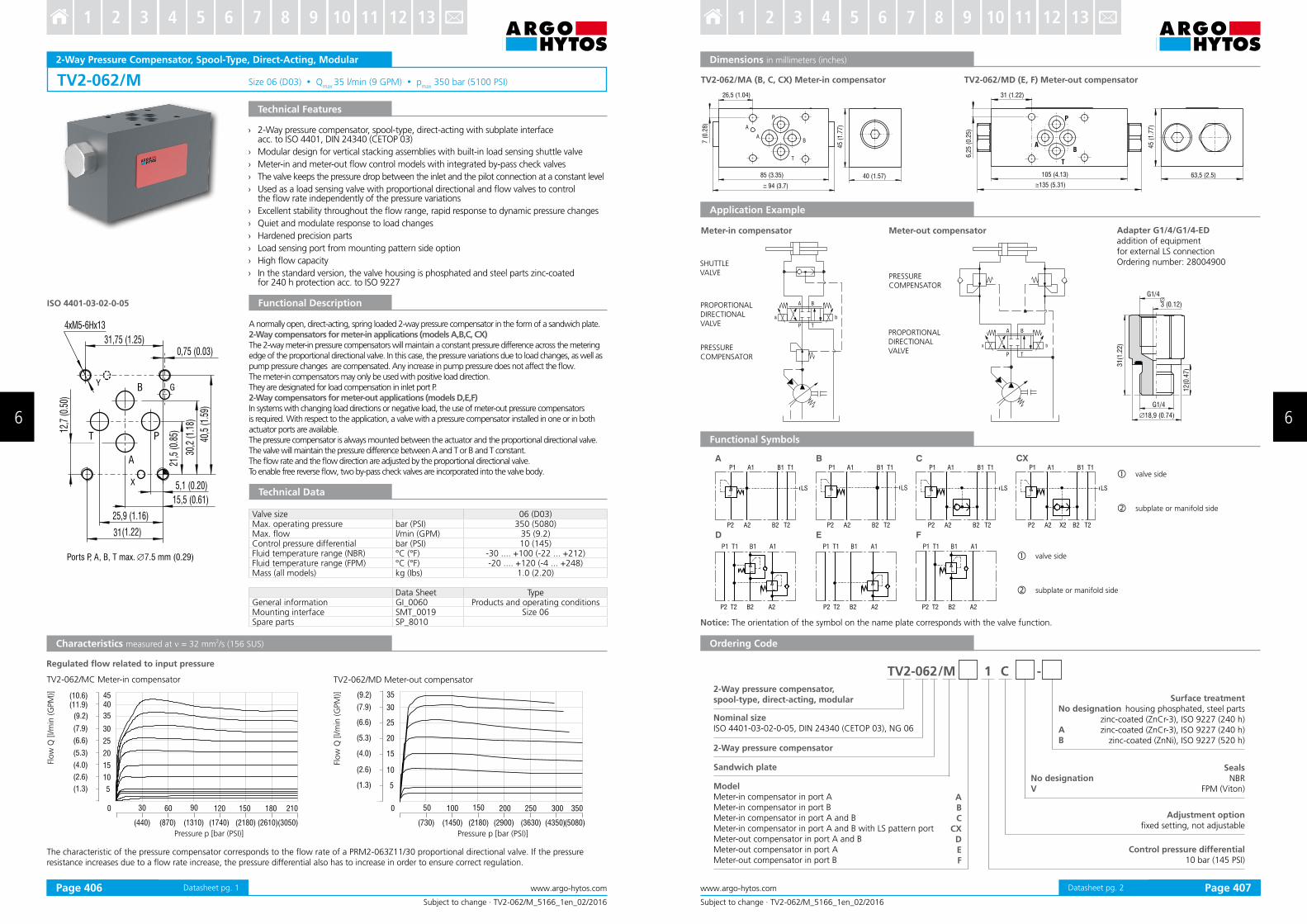
TV2-062/M Size 06 (D03) Qmax
35 l/min (9 GPM) pmax
350 bar (5100 PSI)
0,75 (0.03)
5,1 (0.20)
15,5 (0.61)
25,9 (1.16)
31(1.22)
31,75 (1.25)
T P
B
A
4xM5-6Hx13
12,7
(0.5
0)
21,5
(0.8
5)
30,2
(1.1
8)
40,5
(1.5
9)
GY
X
ISO 4401-03-02-0-05
Ports P, A, B, T max. ∅7.5 mm (0.29)
210
( )2.6
( )4.0
( )1.3
( )7.9
( )9.2
( )5.3
( )6.6
0 30 60 90 120 150
10
15
5
30
35
20
25
180
( )3050( )440 ( )870 ( )1310 ( )2180 ( )2610( )1740
( )11.9 40( )10.6 45
( )2.6
( )4.0
( )1.3
( )7.9
( )9.2
( )5.3
( )6.6
0 50 100 150 200 250
10
15
5
30
35
20
25
300
( )730 ( )1450 ( )2180 ( )3630 ( )4350( )2900
3 05
(5080)
Subject to change · TV2-062/M_5166_1en_02/2016
www.argo-hytos.comPage 1
2-Way Pressure Compensator, Spool-Type, Direct-Acting, Modular
Technical Features
Functional Description
Technical Data
A normally open, direct-acting, spring loaded 2-way pressure compensator in the form of a sandwich plate.2-Way compensators for meter-in applications (models A,B,C, CX)The 2-way meter-in pressure compensators will maintain a constant pressure difference across the metering edge of the proportional directional valve. In this case, the pressure variations due to load changes, as well as pump pressure changes are compensated. Any increase in pump pressure does not affect the low. The meter-in compensators may only be used with positive load direction.They are designated for load compensation in inlet port P.2-Way compensators for meter-out applications (models D,E,F)In systems with changing load directions or negative load, the use of meter-out pressure compensators is required. With respect to the application, a valve with a pressure compensator installed in one or in both actuator ports are available. The pressure compensator is always mounted between the actuator and the proportional directional valve. The valve will maintain the pressure difference between A and T or B and T constant. The low rate and the low direction are adjusted by the proportional directional valve.To enable free reverse low, two by-pass check valves are incorporated into the valve body.
Characteristics measured at ν = 32 mm2/s (156 SUS)
Flow
Q [
l/m
in (
GPM
)]
Pressure p [bar (PSI)]
Flow
Q [
l/m
in (
GPM
)]
Pressure p [bar (PSI)]
› 2-Way pressure compensator, spool-type, direct-acting with subplate interface acc. to ISO 4401, DIN 24340 (CETOP 03)
› Modular design for vertical stacking assemblies with built-in load sensing shuttle valve
› Meter-in and meter-out low control models with integrated by-pass check valves
› The valve keeps the pressure drop between the inlet and the pilot connection at a constant level
› Used as a load sensing valve with proportional directional and low valves to control the low rate independently of the pressure variations
› Excellent stability throughout the low range, rapid response to dynamic pressure changes
› Quiet and modulate response to load changes
› Hardened precision parts
› Load sensing port from mounting pattern side option
› High low capacity
› In the standard version, the valve housing is phosphated and steel parts zinc-coated for 240 h protection acc. to ISO 9227
Valve size 06 (D03)Max. operating pressure bar (PSI) 350 (5080)Max. low l/min (GPM) 35 (9.2)Control pressure differential bar (PSI) 10 (145)Fluid temperature range (NBR) °C (°F) -30 .... +100 (-22 ... +212)Fluid temperature range (FPM) °C (°F) -20 .... +120 (-4 ... +248)Mass (all models) kg (Ibs) 1.0 (2.20)
Data Sheet TypeGeneral information GI_0060 Products and operating conditionsMounting interface SMT_0019 Size 06Spare parts SP_8010
Regulated low related to input pressure
TV2-062/MC Meter-in compensator TV2-062/MD Meter-out compensator
The characteristic of the pressure compensator corresponds to the low rate of a PRM2-063Z11/30 proportional directional valve. If the pressure resistance increases due to a low rate increase, the pressure differential also has to increase in order to ensure correct regulation.
Datasheet pg. 1
P T
A B
ba
26,5 ( .04)1
94 (3.7)
7 (
0.2
8)
T
B
P
A
85 (3.35)
45 (
1.7
7)
40 (1.57)
A
31 (1.22)
6,2
5 (
0.2
5)
105 (4.13)
13 (5. 1)5 3
63,5 (2.5)
45 (
1.7
7)
T
B
P
A
P T
A B
ba
18,9 (0.74)
31
(1.2
2)
G1/4
G1/4
12
(0.4
7)
3 ( . )0 12
P1 T1 B1 A1
P2 T2 B2 A2
P1 A1 B1 T1
P2 A2 B2 T2
P1 A1 B1 T1
P1 T1 B1 A1
P2 T2 B2 A2
P2 A2 B2 T2
P1 A1 B1 T1
P1 T1 B1 A1
P2 T2 B2 A2
P2 A2 B2 T2
P1 A1 B1 T1
P2 A2 X2 B2 T2
LS LS LS LS
D E F
A B C CX
A
BC
CXDEF
TV2-062 /M 1 C -
Subject to change · TV2-062/M_5166_1en_02/2016
www.argo-hytos.com Page 2
Ordering Code
Functional Symbols
Dimensions in millimeters (inches)
Notice: The orientation of the symbol on the name plate corresponds with the valve function.
valve side
subplate or manifold side
Adapter G1/4/G1/4-EDaddition of equipment for external LS connectionOrdering number: 28004900
TV2-062/MA (B, C, CX) Meter-in compensator TV2-062/MD (E, F) Meter-out compensator
Application Example
Meter-in compensator Meter-out compensator
SHUTTLEVALVE
PROPORTIONALDIRECTIONALVALVE
PRESSURECOMPENSATOR
PROPORTIONALDIRECTIONALVALVE
PRESSURECOMPENSATOR
2-Way pressure compensator,spool-type, direct-acting, modular
Nominal sizeISO 4401-03-02-0-05, DIN 24340 (CETOP 03), NG 06
2-Way pressure compensator
Sandwich plate
ModelMeter-in compensator in port AMeter-in compensator in port BMeter-in compensator in port A and BMeter-in compensator in port A and B with LS pattern portMeter-out compensator in port A and BMeter-out compensator in port AMeter-out compensator in port B
Control pressure differential10 bar (145 PSI)
Adjustment optionixed setting, not adjustable
SealsNBR
FPM (Viton)No designationV
No designation
AB
Surface treatment housing phosphated, steel parts
zinc-coated (ZnCr-3), ISO 9227 (240 h)zinc-coated (ZnCr-3), ISO 9227 (240 h)
zinc-coated (ZnNi), ISO 9227 (520 h)
valve side
subplate or manifold side
Datasheet pg. 2Page 406 Page 407
6 6
3 4 5 6 7 8 9 10 11 12 131 2 3 4 5 6 7 8 9 10 11 12 131 2

TV2-102/S M27x2 Qmax
80 l/min (21 GPM) pmax
350 bar (5100 PSI)
50 100 150 200 250 300 3500
40
60
20
80
(725) (1450) (2180) (2900) (3630) (4350)(5080)
( )10.6
( )15.5
( )5.3
( )21.1
B
A
X (LS)
TV2-102/S*C
A
B
X(LS)
B
X(LS)
TV2-102/S*C
TV2-102/S*S(RP)
Subject to change · TV2-102/S_5179_1en_02/2016
www.argo-hytos.comPage 1
2-Way Pressure Compensator, Spool-Type, Direct-ActingFl
ow
Q [
l/m
in (
GPM
)]
Pressure p [bar (PSI)]
Valve size / Cartridge cavity M27x2 / QM3
Max. operating pressure bar (PSI) 350 (5080)
Max. low l/min (GPM) 80 (21.1)
Control pressure differential bar (PSI) 4... 14 (58…203)
Fluid temperature range (NBR) °C (°F) -30.... +100 (-22... +212)
Fluid temperature range (FPM) °C (°F) -20.... +120 (-4... +248)
Mass kg (Ibs) 0.15 (0.3)
Data Sheet Type
General information GI_0060 Products and operating conditions
Valve bodies Sandwich mounted SB-04(06)_0028 SB-*QM3*
Cavity details SMT_0019 SMT-QM3*
Spare parts SP_8010
Technical Features
Functional Description
Technical Data
A normally open, direct-acting, spring loaded pressure compensator in the form of a screw-in cartridge.The outlet of the controlled directional or proportional low valve can be connected back to the pressure compensator port X as a load sensing signal.Typically, 2-way pressure compensators are used in serial connection with a low restrictor valve to control raising or lowering a variable load at the same velocity.The pressure compensator valve then keeps a nearly constant pressure difference between its pressure inlet and the pressure at the output port of the regulated low valve.When the pressure differential exceeds the pre-set value, the pressure compensator closes and restricts the low to the low valve. If there is no low demand from the consumer, the compensator remains open.
Regulated low related to input pressure
The characteristic of the pressure compensator corresponds to the low rate of a PRM2-103Z11/60 proportional directional valve.
If the pressure resistance increases due to a low rate increase, the pressure differential also has to increase in order to ensure correct regulation.
Characteristics measured at ν = 32 mm2/s (156 SUS)
› The valve keeps the pressure drop between the inlet and the pilot connection at a constant level
› Used as a load sensing valve with proportional directional and low valves to control the low rate independently of the pressure variations
› Excellent stability throughout the low range, rapid response to dynamic pressure changes
› Spring setting of the variable adjustment compensator can be varied from 4 to 14 bar (58 to 203 PSI)
› Quiet and modulate response to load changes
› Integrated stroke limiter for reliable operation
› Adjustable by allen key or hand knob, or delivered with ix setting
› Hardened precision parts
› High low capacity
› In the standard version, the valve is zinc-coated for 240 h protection acc. to ISO 9227
Datasheet pg. 1
TV2-102/S*C
505, (1.99)
M27x2
32 (
1.2
6)
23 (
0.9
1)
21 (
0.8
3)
32
63 (2.48)
12,5 (0.49)
5
35
(1
.38
)
M2
7x2
32
(1
.26
)
23
(0
.91
)
21
(0
.83
)
50 5, (1.99)
( .4 )87,5 3 4
32
5
40 (
1.5
7)
max. 31(1.22)
M10x1TV2-102/S*RP
70+5 Nm(51.6+3.7 lbf.ft
TV2-102/S*S
+pp
70+5 Nm(51.6+3.7 lbf.ft)
10+2 Nm(7.4+1.5 lbf.ft)
TV2-102/S -
CSRP
12
M10 x
1
G1/4
27,5 (1.08) 19
10+2 Nm(7.4+1.5 lbf.ft
P T
A B
ba
P T
A B
ba
AB
Subject to change · TV2-102/S_5179_1en_02/2016
www.argo-hytos.com Page 2
Ordering Code
Dimensions in millimeters (inches)
2-Way pressure compensator,spool-type, direct-acting
Cartridge design
2-way pressure compensator
Surface treatmentzinc-coated (ZnCr-3), ISO 9227 (240 h)
zinc-coated (ZnNi), ISO 9227 (520 h)
No designationV
SealsNBR
FPM (Viton)
Adjustment optionixed setting, not adjustable
allen key (hex. 5), without protective caphand knob, plastic
Nominal size M27x2 / QM3
Application Example
Meter-in compensator Meter-out compensator
SHUTTLEVALVE
PROPORTIONALDIRECTIONAL VALVE
PRESSURECOMPENSATOR
PROPORTIONALDIRECTIONAL VALVE
PRESSURECOMPENSATOR
Control pressure differential 4 - 12 bar (58 - 174 PSI), 10 bar (145 PSI) “C” Model10 - 14 bar (145 - 203 PSI), 14 bar (203 PSI) “C” Model
Adapter M10x1/G1/4-EDaddition of equipment for external LS connectionOrdering number:19860700
Applicable only for „TV*C“ versions. (Fixed setting, not adjustable)
Datasheet pg. 2Page 408 Page 409
6 6
3 4 5 6 7 8 9 10 11 12 131 2 3 4 5 6 7 8 9 10 11 12 131 2
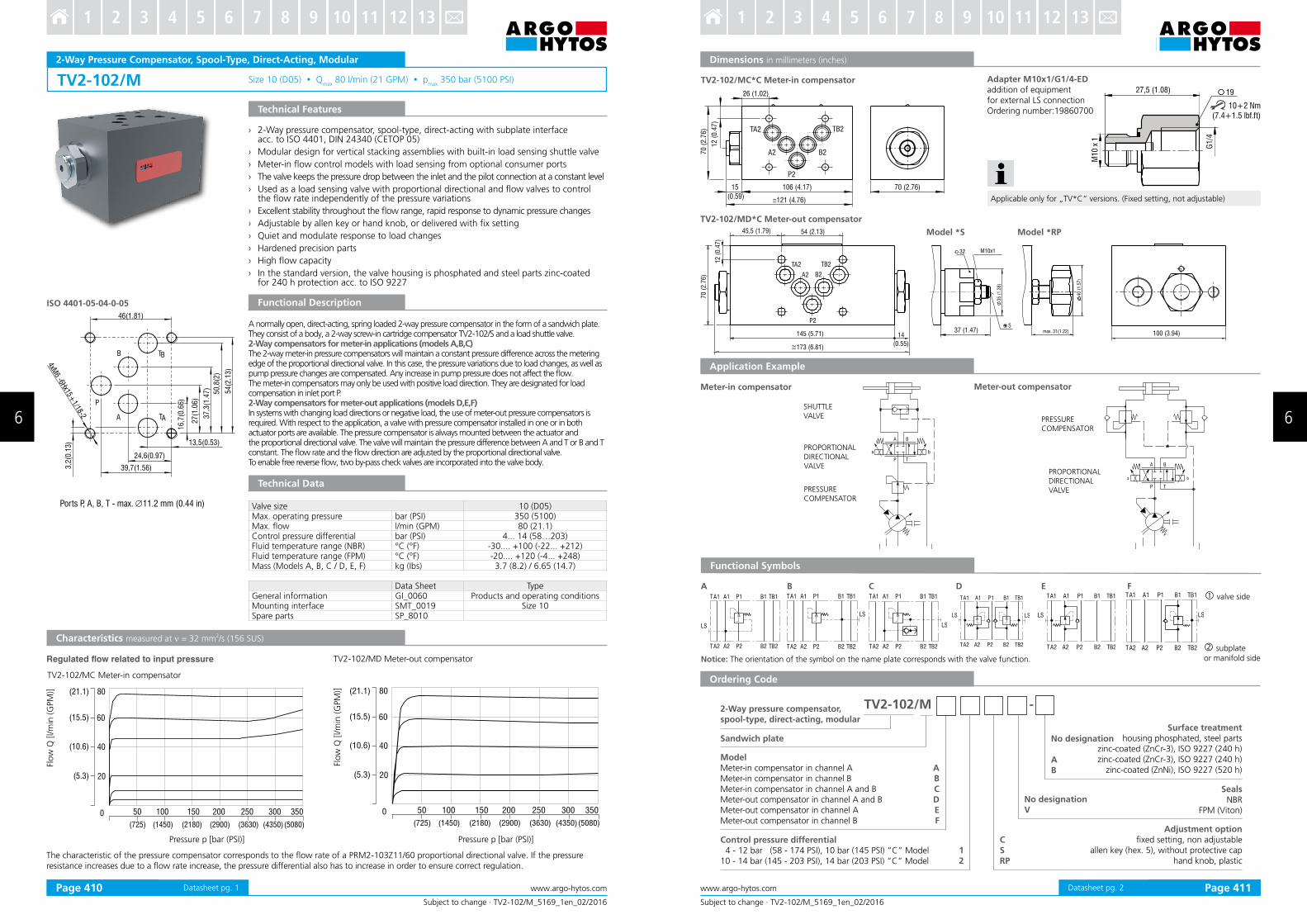
TV2-102/M Size 10 (D05) Qmax
80 l/min (21 GPM) pmax
350 bar (5100 PSI)
13,5(0.53)
24,6(0.97)
39,7(1.56)
46(1.81)
16,7
(0.6
6)
27(1
.06)
37,3
(1.4
7)
50,8
(2)
54(2
.13)
3,2
(0.1
3)
4xM6 -6H
x15+1/18-2 TAA
B
P
TB
ISO 4401-05-04-0-05
50 100 150 200 250 300 3500
40
60
20
80
(725) (1450) (2180) (2900) (3630) (4350)(5080)
( )10.6
( )15.5
( )5.3
( )21.1
50 100 150 200 250 300 3500
40
60
20
80
(725) (1450) (2180) (2900) (3630) (4350)(5080)
( )10.6
( )15.5
( )5.3
( )21.1
Subject to change · TV2-102/M_5169_1en_02/2016
www.argo-hytos.comPage 1
2-Way Pressure Compensator, Spool-Type, Direct-Acting, Modular
Technical Features
Characteristics measured at ν = 32 mm2/s (156 SUS)
Flow
Q [l/m
in (G
PM
)]
Pressure p [bar (PSI)]
Flow
Q [l/m
in (G
PM
)]
Pressure p [bar (PSI)]
Functional Description
Technical Data
Valve size 10 (D05)Max. operating pressure bar (PSI) 350 (5100)Max. low l/min (GPM) 80 (21.1)Control pressure differential bar (PSI) 4... 14 (58…203)Fluid temperature range (NBR) °C (°F) -30.... +100 (-22... +212)Fluid temperature range (FPM) °C (°F) -20.... +120 (-4... +248)Mass (Models A, B, C / D, E, F) kg (Ibs) 3.7 (8.2) / 6.65 (14.7)
Data Sheet TypeGeneral information GI_0060 Products and operating conditionsMounting interface SMT_0019 Size 10Spare parts SP_8010
› 2-Way pressure compensator, spool-type, direct-acting with subplate interface acc. to ISO 4401, DIN 24340 (CETOP 05)
› Modular design for vertical stacking assemblies with built-in load sensing shuttle valve
› Meter-in low control models with load sensing from optional consumer ports
› The valve keeps the pressure drop between the inlet and the pilot connection at a constant level
› Used as a load sensing valve with proportional directional and low valves to control the low rate independently of the pressure variations
› Excellent stability throughout the low range, rapid response to dynamic pressure changes
› Adjustable by allen key or hand knob, or delivered with ix setting
› Quiet and modulate response to load changes
› Hardened precision parts
› High low capacity
› In the standard version, the valve housing is phosphated and steel parts zinc-coated for 240 h protection acc. to ISO 9227
A normally open, direct-acting, spring loaded 2-way pressure compensator in the form of a sandwich plate.They consist of a body, a 2-way screw-in cartridge compensator TV2-102/S and a load shuttle valve.2-Way compensators for meter-in applications (models A,B,C)The 2-way meter-in pressure compensators will maintain a constant pressure difference across the metering edge of the proportional directional valve. In this case, the pressure variations due to load changes, as well as pump pressure changes are compensated. Any increase in pump pressure does not affect the low. The meter-in compensators may only be used with positive load direction. They are designated for load compensation in inlet port P.2-Way compensators for meter-out applications (models D,E,F)In systems with changing load directions or negative load, the use of meter-out pressure compensators is required. With respect to the application, a valve with pressure compensator installed in one or in both actuator ports are available. The pressure compensator is always mounted between the actuator and the proportional directional valve. The valve will maintain the pressure difference between A and T or B and T constant. The low rate and the low direction are adjusted by the proportional directional valve. To enable free reverse low, two by-pass check valves are incorporated into the valve body.
Regulated flow related to input pressure
The characteristic of the pressure compensator corresponds to the low rate of a PRM2-103Z11/60 proportional directional valve. If the pressure resistance increases due to a low rate increase, the pressure differential also has to increase in order to ensure correct regulation.
Ports P, A, B, T - max. ∅11.2 mm (0.44 in)
TV2-102/MC Meter-in compensator
TV2-102/MD Meter-out compensator
Datasheet pg. 1
TV2-102/M -
26 (1.02)
12 (
0.4
7)
106 (4.17) 70 (2.76)
70 (
2.7
6)
121 4.76( )
15
(0.59)
TA2 TB2
B2A2
P2
1
(0.5 )
4
5
54 (2.13)
145 (5.71)
173 (6.81)
45,5 (1.79)
P2
A2 B2
TB2TA2
12
(0
.47
)
100 (3.94)
70
(2
.76
)
35
(1
.38
)
37 (1.47)
32
5
)
max. 31(1.22)
M10x1
40 (
1.5
7
TA1 A1 P1 TB1B1
LS
TA2 A2 P2 TB2B2
TA1 A1 P1 TB1B1
TA2 A2 P2 TB2B2
LS
TA1 A1 P1 TB1B1
TA2 A2 P2 TB2B2
LS
TA1 A1 P1 TB1B1
TA2 A2 P2 TB2B2
LS
TA1 A1 P1 TB1B1
TA2 A2 P2 TB2B2
LS LS
TA1 A1 P1 TB1B1
TA2 A2 P2 TB2B2
LS
P T
A B
ba
P T
A B
ba
Meter-in compensator Meter-out compensator
SHUTTLE VALVE
PROPORTIONAL DIRECTIONAL VALVE
PRESSURECOMPENSATOR
PROPORTIONAL DIRECTIONAL VALVE
PRESSURECOMPENSATOR
M10 x
1
G1/4
27,5 (1.08) 19
10+2 Nm(7.4+1.5 lbf.ft)
A B C D E F
ABCDEF
12
CSRP
Subject to change · TV2-102/M_5169_1en_02/2016
www.argo-hytos.com Page 2
Ordering Code
Functional Symbols
2-Way pressure compensator,spool-type, direct-acting, modular
No designationV
SealsNBR
FPM (Viton)
Dimensions in millimeters (inches)
Notice: The orientation of the symbol on the name plate corresponds with the valve function.
valve side
No designation
AB
Surface treatmenthousing phosphated, steel parts
zinc-coated (ZnCr-3), ISO 9227 (240 h)zinc-coated (ZnCr-3), ISO 9227 (240 h)
zinc-coated (ZnNi), ISO 9227 (520 h)
ModelMeter-in compensator in channel AMeter-in compensator in channel BMeter-in compensator in channel A and BMeter-out compensator in channel A and BMeter-out compensator in channel AMeter-out compensator in channel B
Adjustment optionixed setting, non adjustable
allen key (hex. 5), without protective caphand knob, plastic
Control pressure differential 4 - 12 bar (58 - 174 PSI), 10 bar (145 PSI) “C” Model10 - 14 bar (145 - 203 PSI), 14 bar (203 PSI) “C” Model
TV2-102/MD*C Meter-out compensator
Model *S Model *RP
Adapter M10x1/G1/4-EDaddition of equipmentfor external LS connectionOrdering number:19860700
TV2-102/MC*C Meter-in compensator
Application Example
Sandwich plate
subplateor manifold side
Applicable only for „TV*C“ versions. (Fixed setting, not adjustable)
Datasheet pg. 2Page 410 Page 411
6 6
3 4 5 6 7 8 9 10 11 12 131 2 3 4 5 6 7 8 9 10 11 12 131 2

TV2-063/S M20x1.5 Qmax
40 l/min (11 GPM) pmax
350 bar (5100 PSI)
A
X
B
50 100 150 200 250 300 3500
10
15
5
20
25
(725) (1450) (2180) (2900) (3630) (4350)(5080)
30
35
( )2.6
( )4.0
( )1.3
( )7.9
( )9.2
( )5.3
( )6.6
B
A
X
Subject to change · TV2-063/S_5158_1en_02/2016
www.argo-hytos.comPage 1
3-Way Pressure Compensator, Spool-Type, Direct-Acting
Technical Features
Functional Description
Technical Data
Characteristics measured at ν = 32 mm2/s (156 SUS)
The characteristic of the pressure compensator corresponds with the low rate of a PRM2-043Z11/12and PRM2-063Z11/30 proportional directional valve.
If the pressure resistance increases due to a low rate increase, the pressure differential also has to increase in order to ensure correct regulation.
Flow
Q [
l/m
in (
GPM
)]
Pressure p [bar (PSI)]
› The valve keeps the pressure drop between the inlet and the pilot connection at a constant level
› Used as a load sensing valve with proportional directional and low valves to control the low rate independently of pressure variations
› Excellent stability throughout low range with rapid response to dynamic pressure changes
› Spring setting of the variable adjustment compensator can be varied from 5 to 40 bar (72.5 to 580 PSI)
› Quiet and modulate response to load changes
› Hardened precision parts
› High low capacity
› In the standard version, the valve is zinc-coated for 240 h protection acc. to ISO 9227
A normally closed, direct-acting, spring loaded pressure compensator valve in the form of a screw-in cartridge. From the outlet of the controlled directional or proportional low valve a load sensing signal is taken to the spring chamber of the pressure compensator port X.Typically, 3-way pressure compensators are used as meter-in regulators in parallel with low restrictor valves when raising or lowering variable loads at the same velocity is required.The pressure compensator valve then keeps the pressure difference between its pressure inlet and the pressure at the output port of the regulated low valve nearly constant.When the pressure differential exceeds the pre-set value, the pressure compensator opens and releases excessive low from the main circuit to port B. If there is no low demand from the consumer, the compensator allows the oil to low back to tank and therefore vents the whole system. This prevents the hydraulic system from overheating especially in load sensing circuits with a ixed displacement pump.
Regulated low related to input pressure
Valve size / Cartridge cavity M20x1.5 / QE3
Max. operating pressure bar (PSI) 350 (5080)
Max. low l/min (GPM) 40 (10.6)
Control pressure differential bar (PSI) 5 ... 40 (72.5 …580)
Fluid temperature range (NBR) °C (°F) -30 .... +100 (-22 ... +212)
Fluid temperature range (FPM) °C (°F) -20 .... +120 (-4 ... +248)
Mass kg (Ibs) 0.15 (0.3)
Data Sheet Type
General information GI_0060 Products and operating conditions
Valve bodies Sandwich mounted SB-04(06)_0028 SB-*QE3*
Cavity details SMT_0019 SMT-QE3*
Spare parts SP_8010
Datasheet pg. 1
TV2-063/S -
46 [1.81] 28 [1.1]
88 [3.46]
17
[ 0.6
7]
15
,5
[ 0.6
1]
10
[ 0.3
9
]
M2
0 x
1,5
27
M1
2 x
1
27
6
25+3 Nm (18.4+2.2 lbf.ft)
12+2 Nm (8.9+1.5 lbf.ft)
TV2-063/S
+pp
P
Y
T
A B
X
AB
4 S
Subject to change · TV2-063/S_5158_1en_02/2016
www.argo-hytos.com Page 2
Ordering Code
Application Example
Dimensions in millimeters (inches)
3-Way pressure compensator,spool-type, direct-acting
Pressure range5 - 40 bar (72.5 - 580 PSI)
Cartridge design
3-Way pressure compensator
Surface treatmentzinc-coated (ZnCr-3), ISO 9227 (240 h)
zinc-coated (ZnNi), ISO 9227 (520 h)
No designationV
SealsNBR
FPM (Viton)
Adjustment optionallen key (hex. 6), without protective cap
Nominal sizeM20x1.5 / QE3
FLOW VALVE
PROPORTIONAL PRESSUREVALVE
PRESSUREVALVE
3 WAY PRESSURECOMPENSATOR
Meter-in compensator
Datasheet pg. 2Page 412 Page 413
6 6
3 4 5 6 7 8 9 10 11 12 131 2 3 4 5 6 7 8 9 10 11 12 131 2
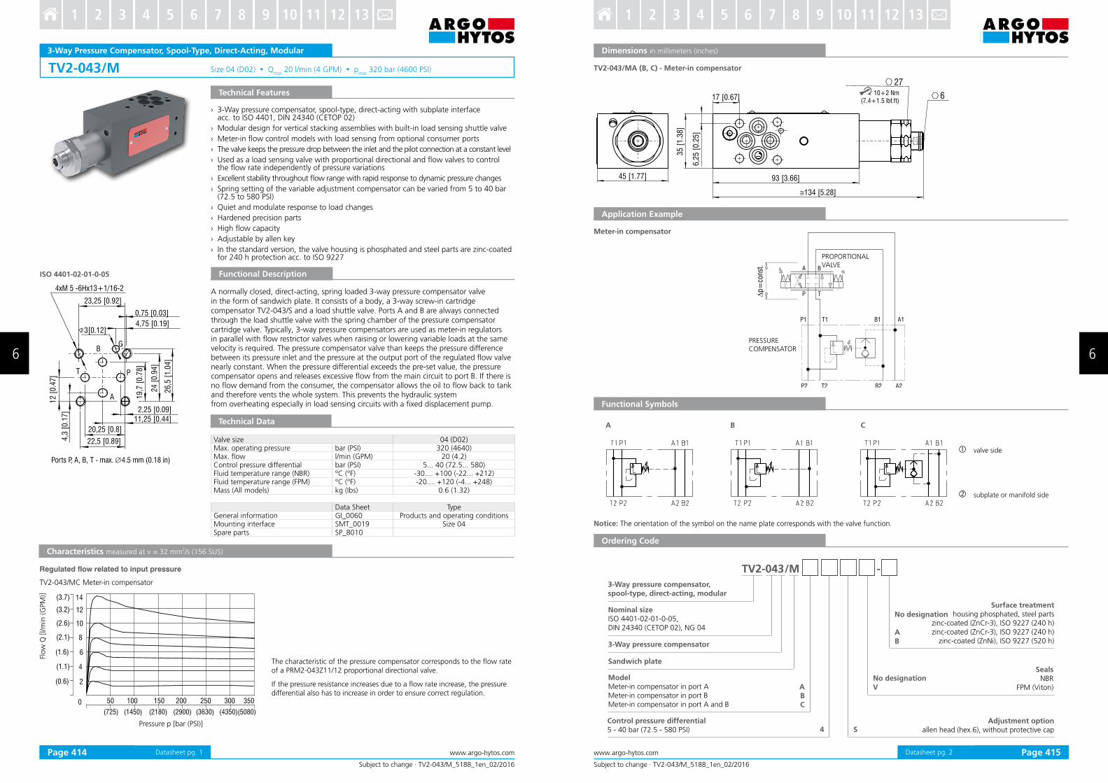
TV2-043/M Size 04 (D02) Qmax
20 l/min (4 GPM) pmax
320 bar (4600 PSI)
4
10
2
14
( .1)1
( .6)2
(0.6)
(3.7)
50 100 150 200 250 300 3500
(725) (1450) (2180) (2900) (3630) (4350)(5080)
8
6
(2. )1
(1.6)
12(3.2)
ISO 4401-02-01-0-05
3[0.12]
22,5 [0.89]
23,25 [0.92]
4,3
[0.1
7]
12 [
0.4
7]
19,7
[0.7
8]
11,25 [0.44]2,25 [0.09]
20,25 [0.8]
24 [
0.9
4]
0,75 [0.03]
4xM 5 -6Hx13+1/16-2
26,5
[1.0
4]
4,75 [0.19]
A
PT
BG
Ports P, A, B, T - max. ∅4.5 mm (0.18 in)
Subject to change · TV2-043/M_5188_1en_02/2016
www.argo-hytos.comPage 1
3-Way Pressure Compensator, Spool-Type, Direct-Acting, Modular
Technical Features
Flow
Q [l/m
in (G
PM
)]
Pressure p [bar (PSI)]
› 3-Way pressure compensator, spool-type, direct-acting with subplate interface acc. to ISO 4401, DIN 24340 (CETOP 02)
› Modular design for vertical stacking assemblies with built-in load sensing shuttle valve
› Meter-in low control models with load sensing from optional consumer ports
› The valve keeps the pressure drop between the inlet and the pilot connection at a constant level
› Used as a load sensing valve with proportional directional and low valves to control the low rate independently of pressure variations
› Excellent stability throughout low range with rapid response to dynamic pressure changes
› Spring setting of the variable adjustment compensator can be varied from 5 to 40 bar (72.5 to 580 PSI)
› Quiet and modulate response to load changes
› Hardened precision parts
› High low capacity
› Adjustable by allen key
› In the standard version, the valve housing is phosphated and steel parts are zinc-coated for 240 h protection acc. to ISO 9227
Functional Description
Technical Data
Valve size 04 (D02)Max. operating pressure bar (PSI) 320 (4640)Max. low l/min (GPM) 20 (4.2)Control pressure differential bar (PSI) 5... 40 (72.5... 580)Fluid temperature range (NBR) °C (°F) -30.... +100 (-22... +212)Fluid temperature range (FPM) °C (°F) -20.... +120 (-4... +248)Mass (All models) kg (Ibs) 0.6 (1.32)
Data Sheet TypeGeneral information GI_0060 Products and operating conditionsMounting interface SMT_0019 Size 04Spare parts SP_8010
A normally closed, direct-acting, spring loaded 3-way pressure compensator valve in the form of sandwich plate. It consists of a body, a 3-way screw-in cartridge compensator TV2-043/S and a load shuttle valve. Ports A and B are always connected through the load shuttle valve with the spring chamber of the pressure compensator cartridge valve. Typically, 3-way pressure compensators are used as meter-in regulators in parallel with low restrictor valves when raising or lowering variable loads at the same velocity is required. The pressure compensator valve than keeps the pressure difference between its pressure inlet and the pressure at the output port of the regulated low valve nearly constant. When the pressure differential exceeds the pre-set value, the pressure compensator opens and releases excessive low from the main circuit to port B. If there is no low demand from the consumer, the compensator allows the oil to low back to tank and therefore vents the whole system. This prevents the hydraulic system from overheating especially in load sensing circuits with a ixed displacement pump.
The characteristic of the pressure compensator corresponds to the low rate of a PRM2-043Z11/12 proportional directional valve.
If the pressure resistance increases due to a low rate increase, the pressure differential also has to increase in order to ensure correct regulation.
Regulated flow related to input pressure
Characteristics measured at ν = 32 mm2/s (156 SUS)
TV2-043/MC Meter-in compensator
Datasheet pg. 1
27
6
6,2
5 [
0.2
5]
17 [0.67]
93 [3.66]
35 [
1.3
8]
45 [1.77]
134 [5.28]
10+2 Nm (7.4+1.5 lbf.ft)
p=ko
nst.
P1 T1 B1 A1
P2 T2 B2 A2
A B
P T
A B C
TV2-043 /M -
A
B
C
4 S
∆p=
cons
t.Subject to change · TV2-043/M_5188_1en_02/2016
www.argo-hytos.com Page 2
Ordering Code
Dimensions in millimeters (inches)
Notice: The orientation of the symbol on the name plate corresponds with the valve function.
valve side
subplate or manifold side
TV2-043/MA (B, C) - Meter-in compensator
PRESSURE
COMPENSATOR
PROPORTIONAL
VALVE
Functional Symbols
Application Example
Meter-in compensator
3-Way pressure compensator,spool-type, direct-acting, modular
No designationV
Nominal sizeISO 4401-02-01-0-05,
DIN 24340 (CETOP 02), NG 04
3-Way pressure compensator
Sandwich plate
ModelMeter-in compensator in port AMeter-in compensator in port BMeter-in compensator in port A and B
SealsNBR
FPM (Viton)
Adjustment option allen head (hex.6), without protective cap
Control pressure differential5 - 40 bar (72.5 - 580 PSI)
No designation
AB
Surface treatmenthousing phosphated, steel parts
zinc-coated (ZnCr-3), ISO 9227 (240 h)zinc-coated (ZnCr-3), ISO 9227 (240 h)
zinc-coated (ZnNi), ISO 9227 (520 h)
Datasheet pg. 2Page 414 Page 415
6 6
3 4 5 6 7 8 9 10 11 12 131 2 3 4 5 6 7 8 9 10 11 12 131 2
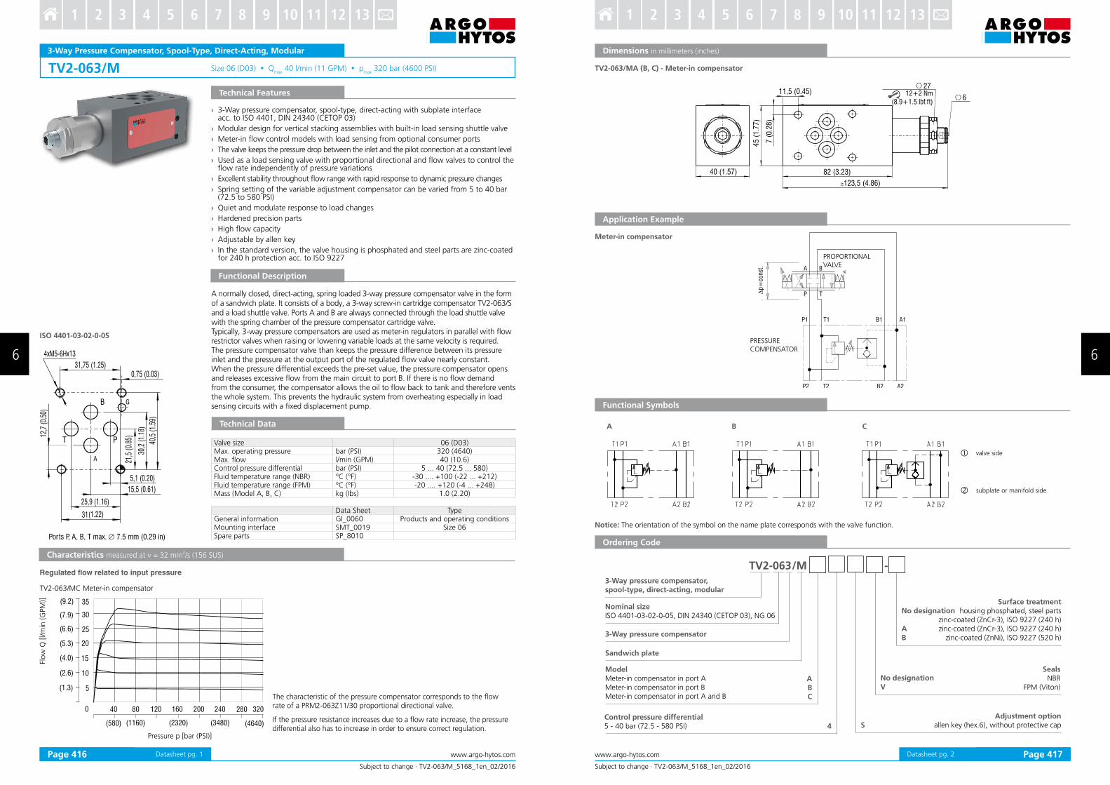
TV2-063/M Size 06 (D03) Qmax
40 l/min (11 GPM) pmax
320 bar (4600 PSI)
0,75 (0.03)
5,1 0.20( )
15,5 (0.61)
25,9 (1.16)
31( )1.22
31,75 (1.25)
T P
B
A
4xM5-6Hx13
12,7
0.50
()
21,5
0.85
()
30,2
1.18
()
40,5
1.59
()
G
ISO 4401-03-02-0-05
10
15
5
20
25
30
35
( )2.6
( )4.0
( )1.3
( )7.9
( )9.2
( )5.3
( )6.6
0 80 24040 120 200 280 320160
( )2320( )1160 ( )4640( )3480( )580
Subject to change · TV2-063/M_5168_1en_02/2016
www.argo-hytos.comPage 1
3-Way Pressure Compensator, Spool-Type, Direct-Acting, Modular
Technical Features
Functional Description
Technical Data
Characteristics measured at ν = 32 mm2/s (156 SUS)
The characteristic of the pressure compensator corresponds to the lowrate of a PRM2-063Z11/30 proportional directional valve.
If the pressure resistance increases due to a low rate increase, the pressure differential also has to increase in order to ensure correct regulation.
Valve size 06 (D03)Max. operating pressure bar (PSI) 320 (4640)Max. low l/min (GPM) 40 (10.6)Control pressure differential bar (PSI) 5 ... 40 (72.5 ... 580)Fluid temperature range (NBR) °C (°F) -30 .... +100 (-22 ... +212)Fluid temperature range (FPM) °C (°F) -20 .... +120 (-4 ... +248)Mass (Model A, B, C) kg (Ibs) 1.0 (2.20)
Data Sheet TypeGeneral information GI_0060 Products and operating conditionsMounting interface SMT_0019 Size 06Spare parts SP_8010
Flow
Q [l/m
in (G
PM
)]
Pressure p [bar (PSI)]
› 3-Way pressure compensator, spool-type, direct-acting with subplate interface acc. to ISO 4401, DIN 24340 (CETOP 03)
› Modular design for vertical stacking assemblies with built-in load sensing shuttle valve
› Meter-in low control models with load sensing from optional consumer ports
› The valve keeps the pressure drop between the inlet and the pilot connection at a constant level
› Used as a load sensing valve with proportional directional and low valves to control the low rate independently of pressure variations
› Excellent stability throughout low range with rapid response to dynamic pressure changes
› Spring setting of the variable adjustment compensator can be varied from 5 to 40 bar (72.5 to 580 PSI)
› Quiet and modulate response to load changes
› Hardened precision parts
› High low capacity
› Adjustable by allen key
› In the standard version, the valve housing is phosphated and steel parts are zinc-coated for 240 h protection acc. to ISO 9227
Regulated flow related to input pressure
A normally closed, direct-acting, spring loaded 3-way pressure compensator valve in the form of a sandwich plate. It consists of a body, a 3-way screw-in cartridge compensator TV2-063/S and a load shuttle valve. Ports A and B are always connected through the load shuttle valve with the spring chamber of the pressure compensator cartridge valve.Typically, 3-way pressure compensators are used as meter-in regulators in parallel with low restrictor valves when raising or lowering variable loads at the same velocity is required.The pressure compensator valve than keeps the pressure difference between its pressure inlet and the pressure at the output port of the regulated low valve nearly constant. When the pressure differential exceeds the pre-set value, the pressure compensator opens and releases excessive low from the main circuit to port B. If there is no low demand from the consumer, the compensator allows the oil to low back to tank and therefore vents the whole system. This prevents the hydraulic system from overheating especially in load sensing circuits with a ixed displacement pump.
TV2-063/MC Meter-in compensator
Ports P, A, B, T max. ∅ 7.5 mm (0.29 in)
Datasheet pg. 1
11,5 (0.45)
7 (
0.2
8)
123,5 (4.86)
82 (3.23)
45 (
1.7
7)
40 (1.57)
27
612+2 Nm
(8.9+1.5 lbf.ft)
p=ko
nst.
P1 T1 B1 A1
P2 T2 B2 A2
A B
P T
A B C
TV2-063 /M -
A
B
C
4 S
∆p=
cons
t.Subject to change · TV2-063/M_5168_1en_02/2016
www.argo-hytos.com Page 2
Ordering Code
Functional Symbols
Dimensions in millimeters (inches)
Notice: The orientation of the symbol on the name plate corresponds with the valve function.
valve side
subplate or manifold side
Application Example
3-Way pressure compensator,spool-type, direct-acting, modular
No designationV
Nominal sizeISO 4401-03-02-0-05, DIN 24340 (CETOP 03), NG 06
3-Way pressure compensator
Sandwich plate
ModelMeter-in compensator in port AMeter-in compensator in port BMeter-in compensator in port A and B
SealsNBR
FPM (Viton)
Adjustment option allen key (hex.6), without protective cap
Meter-in compensator
Control pressure differential5 - 40 bar (72.5 - 580 PSI)
TV2-063/MA (B, C) - Meter-in compensator
PRESSURECOMPENSATOR
PROPORTIONAL VALVE
No designation
AB
Surface treatment housing phosphated, steel parts
zinc-coated (ZnCr-3), ISO 9227 (240 h)zinc-coated (ZnCr-3), ISO 9227 (240 h)
zinc-coated (ZnNi), ISO 9227 (520 h)
Datasheet pg. 2Page 416 Page 417
6 6
3 4 5 6 7 8 9 10 11 12 131 2 3 4 5 6 7 8 9 10 11 12 131 2
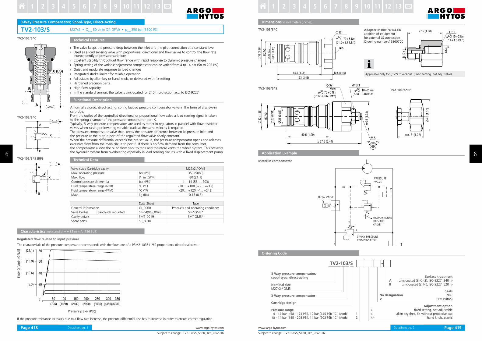
TV2-103/S M27x2 Qmax
80 l/min (21 GPM) pmax
350 bar (5100 PSI)
50 100 150 200 250 300 3500
20
(725) (1450) (2180) (2900) (3630) (4350)(5080)
80(21.1)
( )5.3
60(15.9)
40(10.6)
A
B
X (LS)
TV2-103/S*C
TV2-103/S*C
B
A
X
TV2-103/S*S (RP)
B
A
X
Subject to change · TV2-103/S_5180_1en_02/2016
www.argo-hytos.comPage 1
3-Way Pressure Compensator, Spool-Type, Direct-Acting
Technical Features
Functional Description
Technical Data
Characteristics measured at ν = 32 mm2/s (156 SUS)
Flow
Q [l/m
in (G
PM
)]
Pressure p [bar (PSI)]
Valve size / Cartridge cavity M27x2 / QM3
Max. operating pressure bar (PSI) 350 (5080)
Max. low l/min (GPM) 80 (21.1)
Control pressure differential bar (PSI) 4… 14 (58…. 203)
Fluid temperature range (NBR) °C (°F) -30.... +100 (-22... +212)
Fluid temperature range (FPM) °C (°F) -20.... +120 (-4... +248)
Mass kg (Ibs) 0.15 (0.3)
Data Sheet Type
General information GI_0060 Products and operating conditions
Valve bodies Sandwich mounted SB-04(06)_0028 SB-*QM3*
Cavity details SMT_0019 SMT-QM3*
Spare parts SP_8010
› The valve keeps the pressure drop between the inlet and the pilot connection at a constant level
› Used as a load sensing valve with proportional directional and low valves to control the low rate independently of pressure variations
› Excellent stability throughout low range with rapid response to dynamic pressure changes
› Spring setting of the variable adjustment compensator can be varied from 4 to 14 bar (58 to 203 PSI)
› Quiet and modulate response to load changes
› Integrated stroke limiter for reliable operation
› Adjustable by allen key or hand knob, or delivered with ix setting
› Hardened precision parts
› High low capacity
› In the standard version, the valve is zinc-coated for 240 h protection acc. to ISO 9227
A normally closed, direct-acting, spring loaded pressure compensator valve in the form of a screw-in cartridge. From the outlet of the controlled directional or proportional low valve a load sensing signal is taken to the spring chamber of the pressure compensator port X.Typically, 3-way pressure compensators are used as meter-in regulators in parallel with low restrictor valves when raising or lowering variable loads at the same velocity is required.The pressure compensator valve than keeps the pressure difference between its pressure inlet and the pressure at the output port of the regulated low valve nearly constant. When the pressure differential exceeds the pre-set value, the pressure compensator opens and releases excessive low from the main circuit to port B. If there is no low demand from the consumer, the compensator allows the oil to low back to tank and therefore vents the whole system. This prevents the hydraulic system from overheating especially in load sensing circuits with a ixed displacement pump.
Regulated low related to input pressure
The characteristic of the pressure compensator corresponds with the low rate of a PRM2-103Z11/60 proportional directional valve.
If the pressure resistance increases due to a low rate increase, the pressure differential also has to increase in order to ensure correct regulation.
Datasheet pg. 1
TV2-103/S*C
50 5, (1.99)
M27x2
32 (
1.2
6)
23 (
0.9
1)
21 (
0.8
3)
32
63 (2.48)
12,5 (0.49)
5
35
(1
.38
)
M2
7x2
32
(1
.26
)
23
(0
.91
)
21
(0
.83
)
50 5, (1.99)
( .4 )87,5 3 4
32
5
40
(1
.57)
max. 31(1.22)
M10x1
M10 x
1
G1/4
27,5 (1.08) 19
70+5 Nm (51.6+3.7 lbf.ft)
TV2-103/S*S TV2-103/S*RPValve 70+5 Nm
(51.63+3.69 lbf.ft)
10+2 Nm(7.38+1.48 lbf.ft)
+pp
10+2 Nm(7.4+1.5 lbf.ft)
P
Y
T
A B
X
TV2-103/S -
CSRP
12
AB
Applicable only for „TV*C“ versions. (Fixed setting, not adjustable)
Subject to change · TV2-103/S_5180_1en_02/2016
www.argo-hytos.com Page 2
Dimensions in millimeters (inches)
Application Example
Meter-in compensator
3-Way pressure compensator,spool-type, direct-acting
Pressure range 4 - 12 bar (58 - 174 PSI), 10 bar (145 PSI) “C” Model10 - 14 bar (145 - 203 PSI), 14 bar (203 PSI) “C” Model
Cartridge design
3-Way pressure compensator
Surface treatmentzinc-coated (ZnCr-3), ISO 9227 (240 h)
zinc-coated (ZnNi), ISO 9227 (520 h)
No designationV
SealsNBR
FPM (Viton)
Adjustment optionixed setting, not adjustable
allen key (hex. 5), without protective caphand knob, plastic
Nominal sizeM27x2 / QM3
Ordering Code
Adapter M10x1/G1/4-EDaddition of equipment for external LS connectionOrdering number:19860700
FLOW VALVE
PROPORTIONAL PRESSUREVALVE
PRESSUREVALVE
3 WAY PRESSURECOMPENSATOR
Datasheet pg. 2Page 418 Page 419
6 6
3 4 5 6 7 8 9 10 11 12 131 2 3 4 5 6 7 8 9 10 11 12 131 2

TV2-103/M Size 10 (D05) Qmax
80 l/min (21 GPM) pmax
350 bar (5100 PSI)
13,5(0.53)
24,6(0.97)
39,7(1.56)
46(1.81)
16,7
(0.6
6)
27(1
.06)
37,3
(1.4
7)
50,8
(2)
54(2
.13)
3,2
(0.1
3)
4xM6 -6H
x15+1/18-2 TAA
B
P
TB
50 100 150 200 250 300 3500
20
(725) (1450) (2180) (2900) (3630) (4350)(5080)
80(21.1)
( )5.3
60(15.9)
40(10.6)
Subject to change · TV2-103/M_5170_1en_02/2016
www.argo-hytos.comPage 1
3-Way Pressure Compensator, Spool-Type, Direct-Acting, ModularFl
ow
Q [l/m
in (G
PM
)]
Pressure p [bar (PSI)]
Characteristics measured at ν = 32 mm2/s (156 SUS)
Technical Data
Valve size 10 (D05)
Max. operating pressure bar (PSI) 350 (5100)
Max. low l/min (GPM) 80 (21.1)
Control pressure differential bar (PSI) 4... 14 (58…203)
Fluid temperature range (NBR) °C (°F) -30.... +100 (-22... +212)
Fluid temperature range (FPM) °C (°F) -20.... +120 (-4... +248)
Mass (all models) kg (Ibs) 1.0 (2.2)
Data Sheet Type
General information GI_0060 Products and operating conditions
Mounting interface SMT_0019 Size 10
Spare parts SP_8010
› 3-Way pressure compensator, spool-type, direct-acting with subplate interface acc. to ISO 4401, DIN 24340 (CETOP 05)
› Modular design for vertical stacking assemblies with built-in load sensing shuttle valve
› Meter-in low control models with load sensing from optional consumer ports
› The valve keeps the pressure drop between the inlet and the pilot connection at a constant level
› Used as a load sensing valve with proportional directional and low valves to control the low rate independently of pressure variations
› Excellent stability throughout low range with rapid response to dynamic pressure changes
› Adjustable by allen key or hand knob, or delivered with ix setting
› Quiet and modulate response to load changes
› Hardened precision parts
› High low capacity
› In the standard version, the valve housing is phosphated and steel parts are zinc-coated for 240 h protection acc. to ISO 9227
A normally closed, direct-acting, spring loaded 3-way pressure compensator valve in the form of a sandwich plate. It consists of a body, a 3-way screw-in cartridge compensator TV2-103/S and a load shuttle valve. Ports A and B are always connected through the load shuttle valve with the spring chamber of the pressure compensator cartridge valve.Typically, 3-way pressure compensators are used as meter-in regulators in parallel with low restrictor valves when raising or lowering variable loads at the same velocity is required. The pressure compensator valve than keeps the pressure difference between its pressure inlet and the pressure at the output port of the regulated low valve nearly constant. When the pressure differential exceeds the pre-set value, the pressure compensator opens and releases excessive low from the main circuit to port B. If there is no low demand from the consumer, the compensator allows the oil to low back to tank and therefore vents the whole system. This prevents the hydraulic system from verheating especially in load sensing circuits with a ixed displacement pump.
ISO 4401-05-04-0-05
Ports P, A, B, T - max. ∅11.2 mm (0.44 in)
TV2-103/MC Meter-in compensator
Regulated low related to input pressure
Technical Features
Functional Description
The characteristic of the pressure compensator corresponds to the low rate of a PRM2-103Z11/60 proportional directional valve.
If the pressure resistance increases due to a low rate increase,the pressure differential also has to increase in order to ensure correct regulation.
Datasheet pg. 1
70 (
2.7
6)
70 (2.76)
27
26 (1.02)
12 (
0.4
7)
15 (0.59)
121 (4.76)
106 (4.17)
TA2 TB2
B2A2
P2
35 (
1.3
8)
max. 37 (1.47)
32
5
M10x1
max. 31(1.22)
40 (
1.5
7)
p=ko
nst.
P1 T1 B1 A1
P2 T2 B2 A2
A B
P T
TV2-103 / M -
A B C
M10 x 1
G1/4
27,5
(1.0
8)
19
10+2 Nm (7.4+1.5 lbf.ft)
ABC
12
CSRP
A2 A2P2 TB2B2
TA1 A1P1 TB1B1
LS
LSLS
TA1 A1P1 TB1B1 TA1 A1P1 TB1B1
A2P2 TB2B2A2P2 TB2B2 TA2TA2T
∆p=
cons
t.
Applicable only for „TV*C“ versions.(Fixed setting, not adjustable)
Subject to change · TV2-103/M_5170_1en_02/2016
www.argo-hytos.com Page 2
Dimensions in millimeters (inches)
TV2-103/M* CModel *SModel *RP
Notice: The orientation of the symbol on the name plate corresponds with the valve function.
Sandwich plate
3-Way pressure compensator,spool-type, direct-acting, modular
No designationV
SealsNBR
FPM (Viton)
No designation
AB
Surface treatmenthousing phosphated, steel parts
zinc-coated (ZnCr-3), ISO 9227 (240 h)zinc-coated (ZnCr-3), ISO 9227 (240 h)
zinc-coated (ZnNi), ISO 9227 (520 h)
ModelMeter-in compensator in channel AMeter-in compensator in channel BMeter-in compensator in channel A and B
Adjustment optionixed setting, not adjustable
allen key (hex. 5), without protective caphand knob, plastic
Control pressure differential 4 - 12 bar (58 - 174 PSI), 10 bar (145 PSI) “C” Model10 - 14 bar (145 - 203 PSI), 14 bar (203 PSI) “C” Model
Adapter M10x1/G1/4-EDaddition of equipment for external LS connectionOrdering number: 19860700
Meter-in compensator
Application Example
valve side
subplate or manifold side
Ordering Code
PROPORTIONAL DIRECTIONAL VALVE
PRESSURECOMPENSATORTV2-103/MC
Functional Symbols
Datasheet pg. 2Page 420 Page 421
6 6
3 4 5 6 7 8 9 10 11 12 131 2 3 4 5 6 7 8 9 10 11 12 131 2