1 11 1 aircraft response to control input data collection system presenter: curtis cutright advisor:...
TRANSCRIPT

11
Aircraft Response to Control Input Data Collection System
Presenter: Curtis Cutright
Advisor: Dr. Michael Braasch
Project Sponsor: JUP

22
Presentation Overview
• Motivation
• Data Collection System Block Diagram
• System Component Description
• Unresolved Issues

33
Purpose
• Collect data on the response of the aircraft to the pilot’s control stick inputs»Control stick position, rudder position, body
accelerations, body angular rates, altitude, body position, ground speed, airspeed, etc.
• This data can be used to create a model of the aircraft that can be used in simulations

44
Flight Test Vehicle
• L - 29 Delfin
• High Altitude
• High Speed
• Fully Aerobatic
55
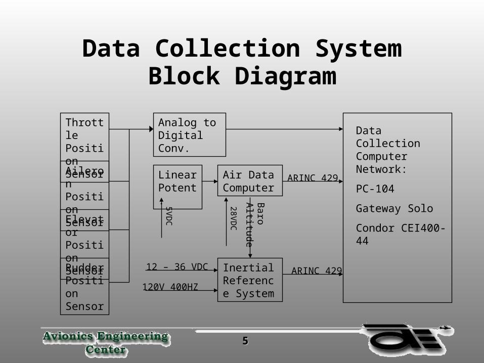
Data Collection System Block Diagram
Throttle Position Sensor
Aileron Position Sensor
Elevator Position Sensor
Rudder Position Sensor
Analog to Digital Conv.
Air Data Computer
Inertial Reference System
Baro
Altitude
Linear Potent.
12 – 36 VDC
120V 400HZ
5VD
C
28VD
C
Data Collection Computer Network:
PC-104
Gateway Solo
Condor CEI400-44
ARINC 429
ARINC 429

66
Block Diagram Description
• Identify the purpose of the each block
• Discuss options to satisfy the requirements of each block
77
Position Sensors
• Continuously monitor the position of the control stick and throttle position
• Monitor the full range of control surface movement
• Critical issues»Safety – must not interfere with control inputs
»Resolution – how much accuracy will we need

88
Position Sensor Options• Linear Variable
Differential Transformer» -35°C to 125°C
» Up to 20g
» Max 50,000 feet
» 1 to 10 VAC 400 Hz
• Rotary Variable Differential Transformer» -55°C to 85°C
» Up to 20g
» Max 20,000 feet
» 3 to 30 VAC 400 Hz
Source:Penny and Giles Website

99
Position Sensor Installation
• Easy accessibility
• Common location
• Best range of motion

1010
Sensor Location Options• Floor under the rear seat»Easily accessible»All the controls in one common location»May limit range of motion
• At the control surface»Harder to access»More wiring due to remote locations»Outside the pressure bulkhead
• On the control surface»Good range of motion»May interfere with surface movements

1111
Sensor Locations Options (cont.)
Elevator, Rudder, & Ailerons

1212
Sensor Locations Options (cont.)
Elevator, Rudder, & Ailerons

1313
Sensor Locations Options (cont.)
Throttle

1414
Analog to Digital Converter
• Monitor the control system position signals
• Digitize control system position sensor signals
• Prepare the signal for processing» Identify which signal is being sent
»Tag the signal
»Convert it for transmission

1515
Linear Potentiometer
• Provide barometric altimeter correction to the Air Data Computer

1616
Air Data Computer
• Provide barometric altitude to the Inertial Reference System
• Sends airspeed information to the data collection system

1717
Data Collection System
• PC-104 serves as a platform for the Condor CEI400-44 ARINC 429 Interface Card
• Gateway Solo laptop is used as the data storage unit and runs the data collection programs
• Time stamps the collected information»Time stamp can be set as low as 1ms

1818
Inertial Reference System
• Primary source of information
• Sends several parameters to the data collection system»Ground Speed – 10 Hz
»Body Accelerations – 50 Hz
»Body Rates – 50 Hz
»Altitude – 25 Hz
»Roll and Pitch Angle – 50 Hz

1919
Unresolved Issues
• Method of collecting control input information
• Formatting the control input signals
• Safety issues in installing the control system position sensors
• What data to collect and what rates at which to collect it
• Coordination of control system data with aircraft response data

2020
Conclusion
• Collecting the inertial data is a fairly straightforward process
• Collecting the control system data will require more time to develop the necessary methods and systems

2121
Questions?