1 1. introduction 2. r&d status using prototype detector 3. summary xmass experiment 8 th june...
Post on 21-Dec-2015
220 views
TRANSCRIPT

1
1. Introduction2. R&D status using prototype detector3. Summary
XMASS experiment8th June 2005
A. Takeda for the XMASS collaborationKamioka Observatory, ICRR,University of Tokyo
WIN05
2
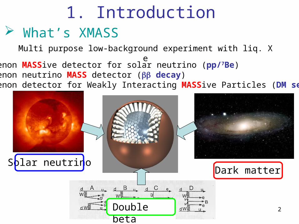
1. Introduction
Dark matter
Double beta
Solar neutrino
What’s XMASS
Xenon MASSive detector for solar neutrino (pp/7Be) Xenon neutrino MASS detector ( decay) Xenon detector for Weakly Interacting MASSive Particles (DM search)
Multi purpose low-background experiment with liq. Xe
3
Why liquid xenon
Large Z (=54) Self-shielding effect Large photon yield (~42 photons/keV ~ NaI(Tl)) Low threshold High density (~3 g/cm3) Compact detector (10 ton: sphere with diameter of ~2m) Purification (distillation)
No long life radioactive isotope Scintillation wavelength (175 nm, detected directly by PMT) Relative high temperature (~165 K)

4
PMTs
Single phaseliquid Xe Volume for shielding
Fiducial volume
23ton all volume20cm wall cut30cm wall cut (10ton FV)
BG
nor
ma
lize
d b
y m
ass
1MeV0 2MeV 3MeV
Large self-shield effect
External ray from U/Th-chain
Key idea: self-shielding effect for low energy events

5
100kg Prototype 800kg detector
10 ton detector
~ 30cm~ 80cm
~ 2.5m
R&DDark matter search
Multipurpose detector
(solar neutrino, …)
We are now here
Strategy of the scale-up
With light guide
6
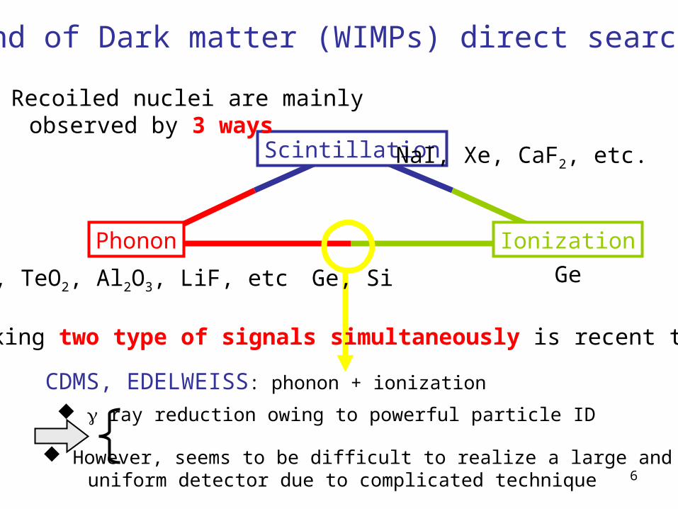
Trend of Dark matter (WIMPs) direct searches
Scintillation
Phonon Ionization
Ge, TeO2, Al2O3, LiF, etc
NaI, Xe, CaF2, etc.
Ge
Recoiled nuclei are mainly observed by 3 ways
CDMS, EDELWEISS: phonon + ionization
Taking two type of signals simultaneously is recent trend
ray reduction owing to powerful particle ID
However, seems to be difficult to realize a large and uniform detector due to complicated technique
Ge, Si
7
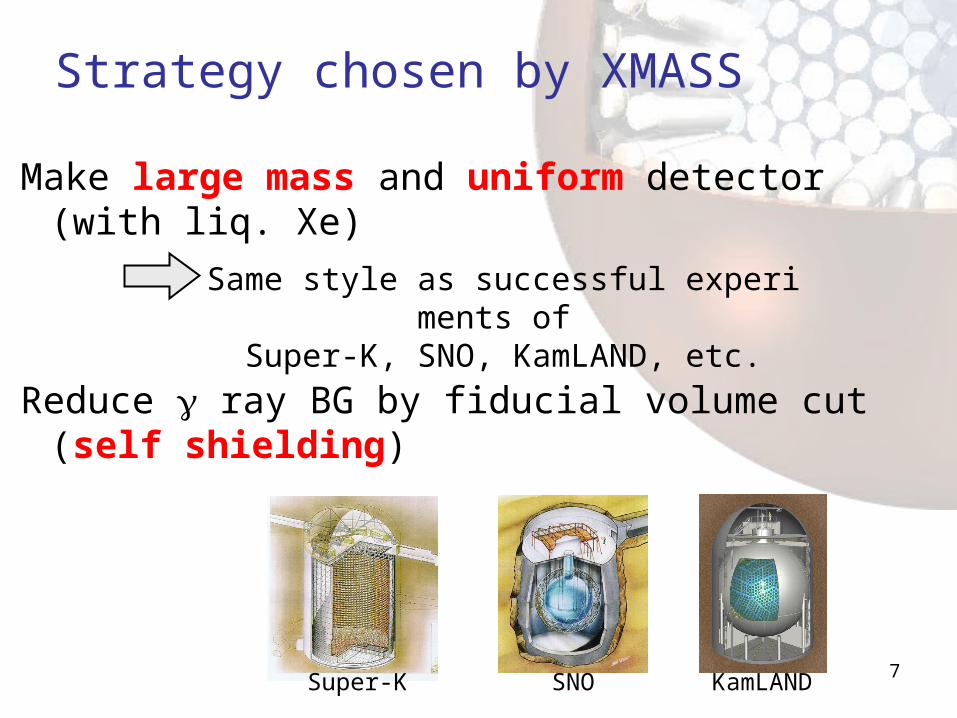
Strategy chosen by XMASS
Make large mass and uniform detector (with liq. Xe)
Reduce ray BG by fiducial volume cut (self shielding)
Same style as successful experiments of Super-K, SNO, KamLAND, etc.
Super-K KamLANDSNO

8
800 kg detector
Main purpose: Dark Matter search
~800-2” PMTs immersed into liq. Xe 70% photo-coverage
~80cm diameter
~5 keVee threshold
External ray BG: 60cm, 346kg 40cm, 100kg
Expected dark matter signal(assuming 10-42 cm2, Q.F.=0.2 50GeV / 100GeV,)
pp & 7Be solar
Achieved
9
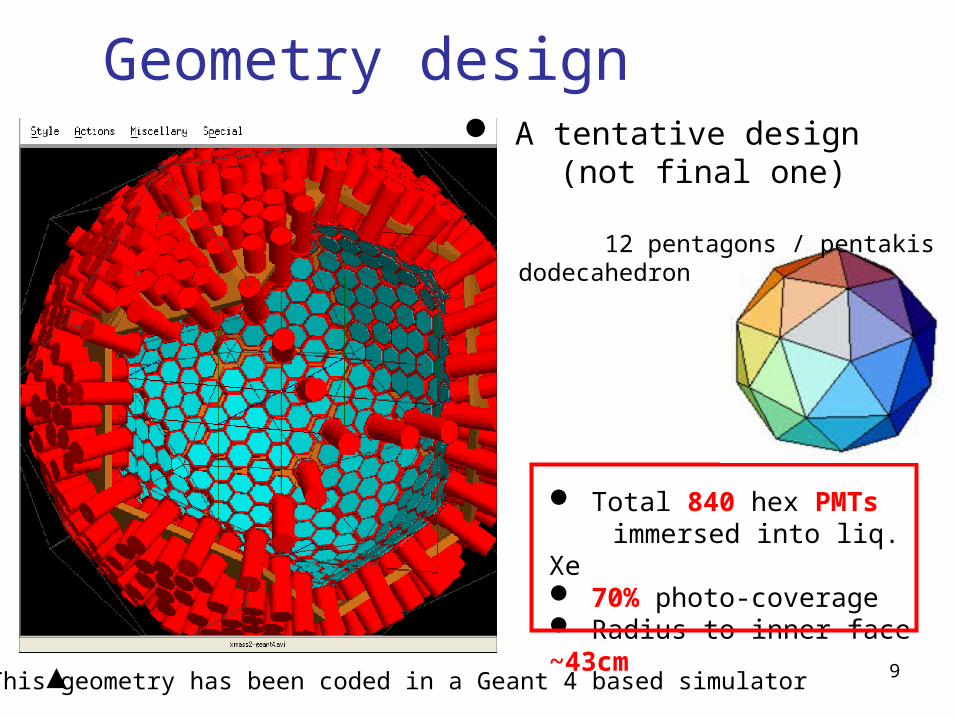
Geometry design A tentative design (not final one)
Total 840 hex PMTs immersed into liq. Xe 70% photo-coverage Radius to inner face ~43cm
12 pentagons / pentakisdodecahedron
This geometry has been coded in a Geant 4 based simulator
10
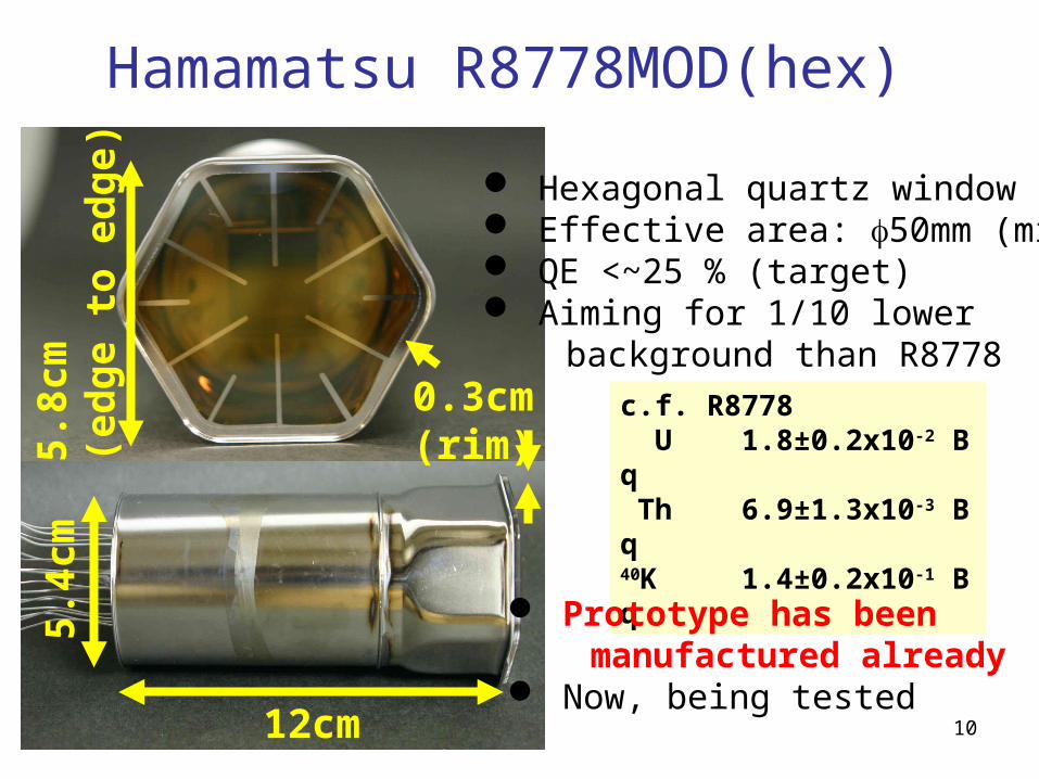
Hamamatsu R8778MOD(hex)
12cm
5.4c
m5.
8cm
(ed
ge
to e
dg
e)
0.3cm(rim)
c.f. R8778 U 1.8±0.2x10⁻² Bq Th 6.9±1.3x10⁻³ Bq40K 1.4±0.2x10⁻¹ Bq
Hexagonal quartz window Effective area: 50mm (min) QE <~25 % (target) Aiming for 1/10 lower background than R8778
Prototype has been manufactured already Now, being tested

11
Expected sensitivities
Large improvements will be expected SI ~ 10-45 cm2 = 10-9 pb SD~ 10-39 cm2 = 10-3 pb
XMASS(Ann. Mod.)
XMASS(Sepc.)
Edelweiss Al2O3
Tokyo LiF
Modane NaI
CRESST
UKDMC NaI
NAIAD
XMASS FV 0.5 ton yearEth = 5 keVee~25 p.e., 3 discoveryw/o any pulse shape info.
10-6
10-4
10-8
10-10
Cro
ss s
ectio
n to
nuc
leon
[p
b]
10-4
10-2
1
102
104
106
Plots except for XMASS: http://dmtools.berkeley.eduGaitskell & Mandic

12
100kg prototype
With light guide version
2. R&D status using prototype detector
Main purpose
Confirmation of estimated 800 kg detector performance
BG study
Vertex and energy reconstruction by fitter Miss fitting due to dead angle of the cubic detector (“wall effect”, will be explained later) can be removed with light guide Self shielding power
Understanding of the source of BG Measuring photon yield and its attenuation length
~30 cm cube3 kg fiducial
13
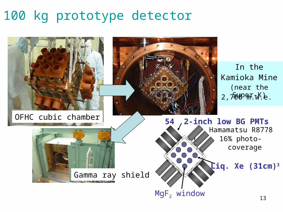
In theKamioka Mine
(near the Super-K)
Gamma ray shield
OFHC cubic chamber
Liq. Xe (31cm)3
MgF2 window
54 2-inch low BG PMTs
16% photo- coverage
Hamamatsu R8778
2,700 m.w.e.
100 kg prototype detector
14
1.0m
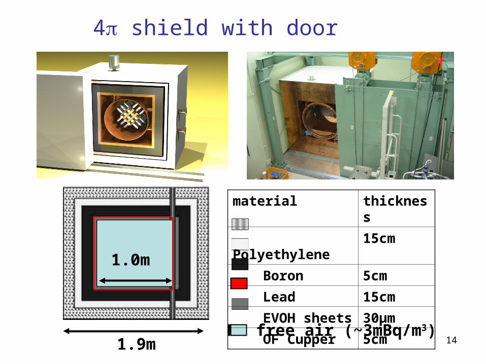
1.9mRn free air (~3mBq/m3)
material thickness
Polyethylene 15cm
Boron 5cm
Lead 15cm
EVOH sheets 30μm
OF Cupper 5cm
4 shield with door
15
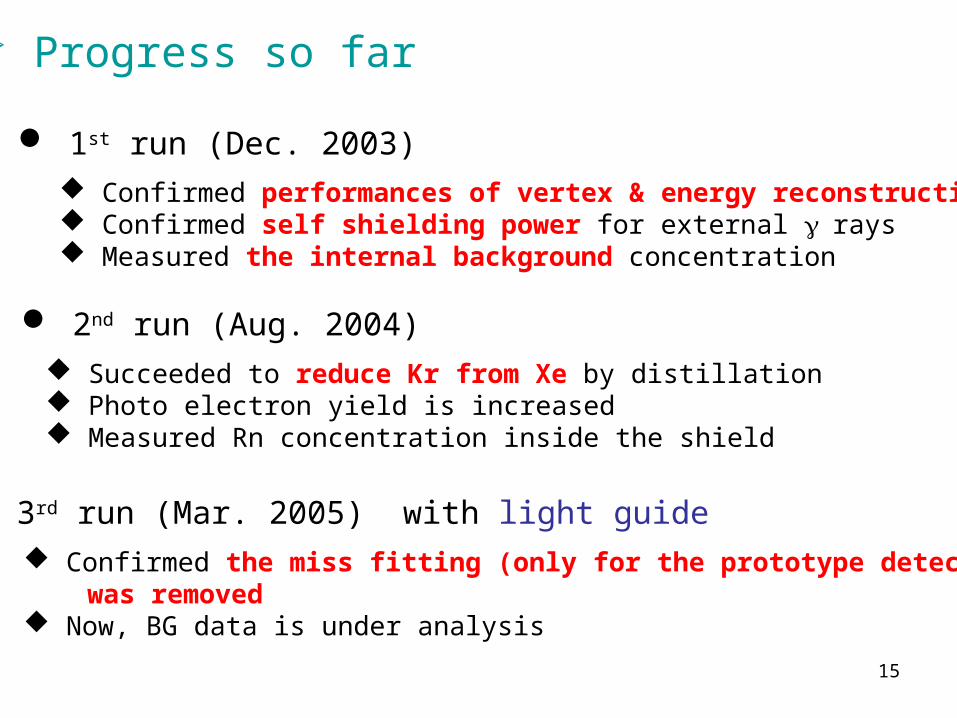
Progress so far
1st run (Dec. 2003)
2nd run (Aug. 2004)
3rd run (Mar. 2005) with light guide
Confirmed performances of vertex & energy reconstruction Confirmed self shielding power for external rays Measured the internal background concentration
Succeeded to reduce Kr from Xe by distillation Photo electron yield is increased Measured Rn concentration inside the shield
Confirmed the miss fitting (only for the prototype detector) was removed Now, BG data is under analysis

16
PMT
n
nL )
!
)exp(Log()Log(
L: likelihood
: F(x,y,z,i)
x total p.e. F(x,y,z,i)
n: observed number of p.e.
=== Background event sample === QADC, FADC, and hit timing information are available for analysis
F(x,y,z,i): acceptance for i-th PMT (MC)VUV photon characteristics:
Lemit=42ph/keVabs=100cm
scat=30cm
Calculate PMT acceptances from various vertices by Monte Carlo. Vtx.: compare acceptance map F(x,y,z,i) Ene.: calc. from obs. p.e. & total accept.
Reconstructedhere
FADC Hit timing
QADC
Reconstruction is performed by PMT charge pattern (not timing)
Vertex and energy reconstruction
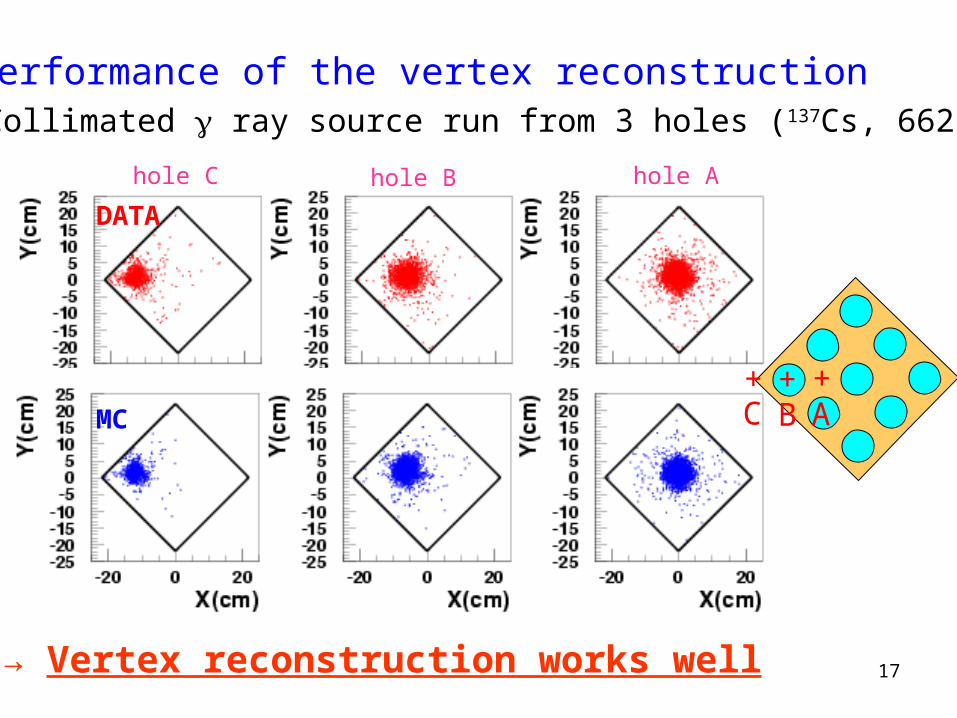
17→ Vertex reconstruction works well
1. Performance of the vertex reconstruction Collimated ray source run from 3 holes (137Cs, 662keV)
DATA
MC
hole Ahole Bhole C
ABC+++
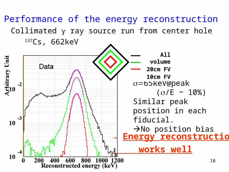
18
65keV@peak(/E ~ 10%)
Similar peak position in each fiducial.No position bias
2. Performance of the energy reconstruction Collimated ray source run from center hole
137Cs, 662keV
→ Energy reconstruction
works well
All volume20cm FV10cm FV

19
z position distribution of the collimated ray source run
→ Data and MC agree wellγ
Demonstration of self shielding effect

20
Shelf shielding for real data and MC
Good agreement (< factor 2) Self shielding effect can be seen clearly. Very low background (10-2 /kg/day/keV@100-300 keV)
REAL DATA MC simulation
All volume20cm FV
10cm FV(3kg)
All volume20cm FV
10cm FV(3kg)
Miss-reconstruction due to dead-angle region from PMTs.
Eve
nt r
ate
(/kg
/day
/keV
)
10-2/kg/day/keV
Aug. 04 runpreliminary
3.9dayslivetime
~1.6Hz, 4 fold, triggered by ~0.4p.e.
21
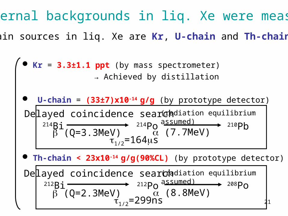
Kr = 3.3±1.1 ppt (by mass spectrometer)
→ Achieved by distillation
U-chain = (33±7)x10-14 g/g (by prototype detector)
Th-chain < 23x10-14 g/g(90%CL) (by prototype detector)
1/2=164s (Q=3.3MeV) (7.7MeV)
214Bi 214Po 210Pb
1/2=299ns (Q=2.3MeV) (8.8MeV)
212Bi 212Po 208Po
Delayed coincidence search
Delayed coincidence search
(radiation equilibrium assumed)
(radiation equilibrium assumed)
Internal backgrounds in liq. Xe were measured
Main sources in liq. Xe are Kr, U-chain and Th-chain

22
Kr 0.1ppm
DM signal(10-6 pb, 50GeV,100 GeV)
0 200 400 600 800
1
102
10-2
10-4
10-6
cpd/
kg/k
eV
energy (keV)
Target = Xe
Kr concentration in Xe
85Kr makes BG in low enegy region
Kr can easily mix with Xe because both Kr and Xe are rare gas
Commercial Xe contains a few ppb Kr

23
XMASS succeeds to reduce Kr concentration in Xe
from ~3[ppb] to 3.3(±1.1)[ppt] with one cycle (~1/1000)
~3mLower
Higher
~1%
~99%
Purified Xe: 3.3±1.1 ppt Kr (measured)
Off gas Xe:330±100 ppb Kr(measured)
Raw Xe: ~3 ppb Kr
(preliminary)
(178K)
(180K)Operation@2atm
• Processing speed : 0.6 kg / hour• Design factor : 1/1000 Kr / 1 pass• Purified Xe : Off gas = 99:1
Xe purification system
Boiling point
(@2 atm)
Xe 178.1K
Kr 129.4K
24
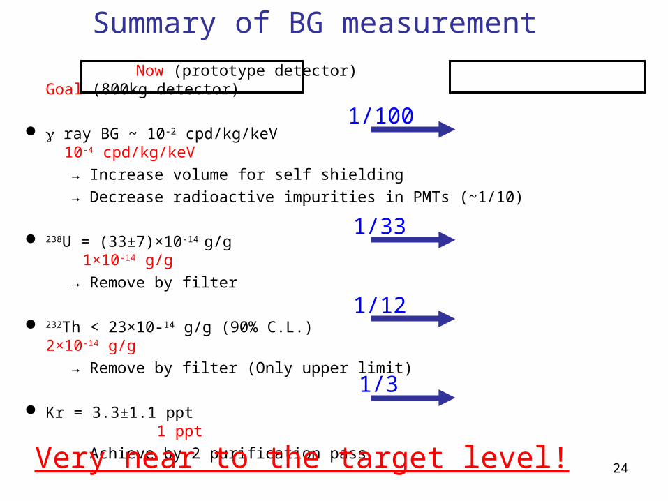
Now (prototype detector) Goal (800kg detector)
ray BG ~ 10-2 cpd/kg/keV 10-4 cpd/kg/keV
→ Increase volume for self shielding
→ Decrease radioactive impurities in PMTs (~1/10)
238U = (33±7)×10-14 g/g 1×10-14 g/g
→ Remove by filter
232Th < 23×10-14 g/g (90% C.L.) 2×10-14 g/g
→ Remove by filter (Only upper limit)
Kr = 3.3±1.1 ppt 1 ppt
→ Achieve by 2 purification pass
Very near to the target level!
1/100
1/33
1/12
1/3
Summary of BG measurement
25
HIT
HIT
HIT
HIT
HIT
?
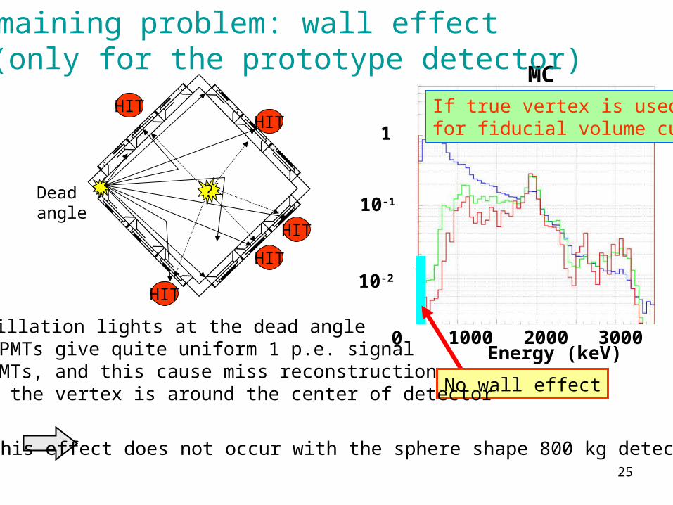
MCIf true vertex is usedfor fiducial volume cut
10-2
1
10-1
Energy (keV)0 1000 2000 3000
No wall effect
Remaining problem: wall effect (only for the prototype detector)
Scintillation lights at the dead angle from PMTs give quite uniform 1 p.e. signal for PMTs, and this cause miss reconstruction as if the vertex is around the center of detector
Deadangle
This effect does not occur with the sphere shape 800 kg detector

26
PTFE light guide(UV reflection)
Active veto
Fiducial
Prototype detector with light guide
10cm
10cm10cm
Purpose: remove the wall effect and understand the source of BG in the DM region
6 pieces
10X10X10cm3
(~3 kg Xe)

27
222Rn decays (210Pb 64 keV endpoint) implanted in PTFE surfaces
might make the dominant BG
air
PTFE
222Rn
218Po
214Pb
210Pb
α
α
α
Position distribution of 210Pb (in NaI)
Light guide setup
Implanted to ~0.1μm
N.J.T. Smith et al., Phys. Lett. B 485 (2000) 9
We edged the PTFE inside ~10μm
Recoil process implants30% of the original surface Rn decays
Edging of PTFE surfaces
0 0.05 0.10 0.15Z [m]
28
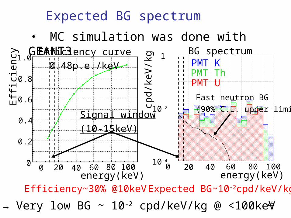
・ MC simulation was done with GEANT3
0 20 40 60 80
10-2
10-4
1
1001000 20 40 60 800
0.4
0.2
0.6
0.8
1.0
Eff
icie
ncy
cpd/
keV
/kg
energy(keV) energy(keV)
Efficiency curve BG spectrum
Signal window
(10-15keV)
Efficiency~30% @10keV Expected BG~10-2cpd/keV/kg
Fast neutron BG
(90% C.L. upper limit)
0.48p.e./keV PMT KPMT ThPMT U
→ Very low BG ~ 10-2 cpd/keV/kg @ <100keV
Expected BG spectrum

29Energy [keV]
Co
unt
s
10cm fiducial
fiducialvolumeC
ou
nts
Energy [keV]
w/o light guide
Reduce the events due to the wall effect
Hole-B
Result 1: comparing the data taken with and without light guide
with light guide
Collimated ray source run from hole-B (137Cs, 662keV)
30
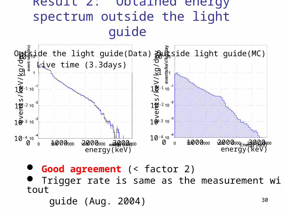
Outside the light guide(Data)
0 1000 2000 300010-4
10-3
10-2
10-1
1
10
energy(keV)
even
ts/k
eV/k
g/da
y
Live time (3.3days)
Outside light guide(MC)
0 1000 2000 300010-4
10-3
10-2
10-1
1
10
energy(keV)ev
ents
/keV
/kg/
day
Result 2: Obtained energy spectrum outside the light guide
Good agreement (< factor 2) Trigger rate is same as the measurement witout guide (Aug. 2004)

31
3. Summary XMASS experiment: Multi purpose low-background experiment with large mass liq. Xe
800 kg detector: Designed for dark matter shearch mainly, and 102 improvement of sensitivity above existing experiments is expected
R&D with the 100 kg prototype detector Most of the performances required for 800 kg detector are confirmed

32

33
XMASS collaboration• ICRR, Kamioka Y. Suzuki, M. Nakahata, Y. Itow, S. Moriyama, M. Shiozawa, Y. Takeuchi , M. Miura, Y. Koshio, K. Ishihara, K. Abe, A. Takeda, T. Namba, H. Ogawa, S. Fukuda, Y. Ashie, A. Minamino, R. Nambu, J. Hosaka, K. Taki, T. Iida, K. Ueshima• ICRR, RCNN T. Kajita, K. Kaneyuki• Saga Univ. H. Ohsumi, Y. Iimori,• Tokai Univ. K. Nishijima, T. Hashimoto, Y. Nakajima, Y. Sakurai• Gifu Univ. S. Tasaka• Waseda Univ. S. Suzuki, K. Kawasaki, J. Kikuchi, T. Doke, A. O
ta• Yokohama National Univ. S. Nakamura, T.Fukuda, S. Oda, N. Kobayashi, A. Hashimoto• Miyagi Univ. of Education Y. Fukuda, T. Sato• Seoul National Univ. Soo-Bong Kim, In-Seok Kang• INR-Kiev Y. Zdesenko, O. Ponkratenko• UCI H. Sobel, M. Smy, M. Vagins, P.Cravens• Sejong univ. Y. Kim • Ewha Womans Univ. K. Lim• Indiana Univ. M. Ishitsuka

34
Electronics of light guide run (Mar. 2005)
ADC
Triggermodule
Gategenerator
SumAmp
delayPMT
PMT
PMT
PMT
Fan-out
x8
SumAmp
x8
Discri(VME)Discri(NIM)~1/4p.e.thres.FADC(2ch/250MHz) 16μs
ID sumOD sum
ID sumOD sum
ID x8
FADC(8ch/500MHz) 1μs
Gain : 8.25×10⁶
ID 2hit≧
OD 4hit≧
400ns
InnerPMT×6
OuterPMT×48
35
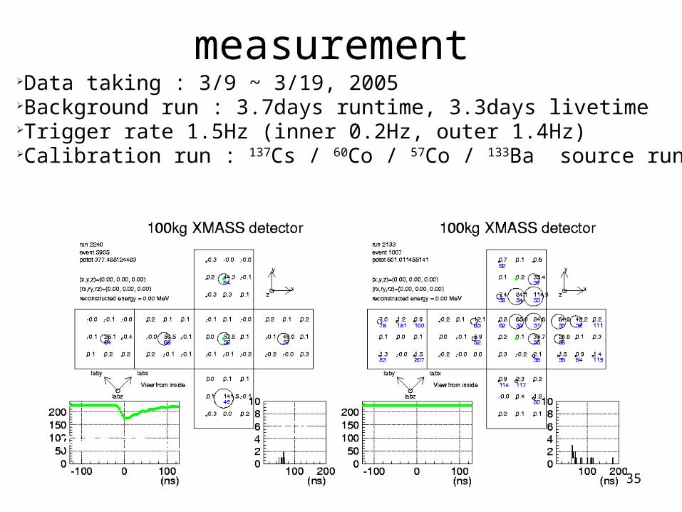
measurement➢Data taking : 3/9 ~ 3/19, 2005➢Background run : 3.7days runtime, 3.3days livetime➢Trigger rate 1.5Hz (inner 0.2Hz, outer 1.4Hz) ➢Calibration run : 137Cs / 60Co / 57Co / 133Ba source run
ID hit event
FADC ID sumTDC
OD hit event
36
Background study
keV0 1000 2000 3000
1
10-1
10-2
cpd/
kg/k
eV
Outside of the shield
238U in PMTs232Th in PMTs
40K in PMTs
210Pb in lead shield
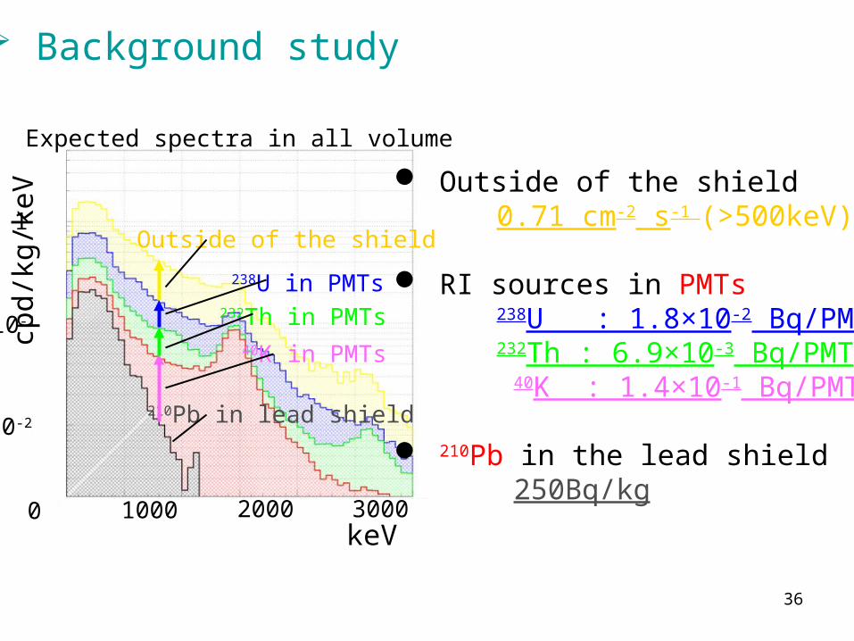
Outside of the shield 0.71 cm-2 s-1 (>500keV)
RI sources in PMTs 238U : 1.8×10⁻² Bq/PMT 232Th : 6.9×10⁻³ Bq/PMT 40K : 1.4×10⁻¹ Bq/PMT
210Pb in the lead shield 250Bq/kg
Expected spectra in all volume
37
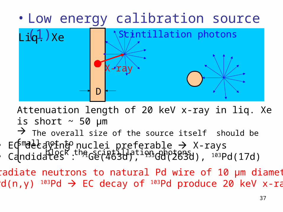
• Low energy calibration source (1)
Attenuation length of 20 keV x-ray in liq. Xe is short ~ 50 μm The overall size of the source itself should be small not to block the scintillation photons
Irradiate neutrons to natural Pd wire of 10 μm diameter102Pd(n,γ) 103Pd EC decay of 103Pd produce 20 keV x-ray
X-ray
Scintillation photons
D
• EC decaying nuclei preferable X-rays• Candidates : 71Ge(463d), 153Gd(263d), 103Pd(17d)
Liq. Xe

38
• Low energy calibration source (2) ☆ 125I(X-ray source) : 27.5 keV (59.9day)
☆ Temperature Range : -200 ~ +100 in Centigrade
☆ Overall source diameter < 20 mm
☆ Weak source ~ a few kBq
Length60mm
125I (1kBq)Electrodeposition
Material AF= 10mm
CoatingMaterial BThick=3mm
5mm
Sourceposition
Liq. Xe
39
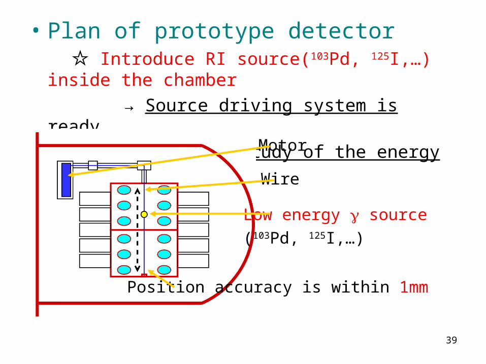
• Plan of prototype detector ☆ Introduce RI source(103Pd, 125I,…) inside the
chamber
→ Source driving system is ready
→ Detailed study of the energy and vertex fitter
Low energy source
(103Pd, 125I,…)
Wire
Motor
Position accuracy is within 1mm

40

41

42